Loading ...
Loading ...
3
1. PREPARE THE INSTALLATION
NOTE: Before proceeding to the installation, check the contents of the box. If items are missing or damaged, contact the manufacturer.
Make sure that the following items are included:
- Hood
- Accessories • Decorative flue assembly (lower and upper flues)
• Hood mounting bracket
• Upper flue mounting bracket
• 2 hybrid filters
• 6” round adapter/damper (for vertical discharge), in a bag
• 3¼” x 10” adapter/damper (for horizontal or vertical discharge)
• Bag of parts including: 5 no. 8 x 1½” countersunk screws, 8 no. 8 x 3/4” screws, 6 no. 8 x 3/8” screws,
6 drywall anchors, 3 washers, 2 no. 8 x 1/2” screws, 2 neoprene pieces. If need be,
discard extra hardware.
Parts sold separately:
- Duct, elbows, wall or roof caps.
- Optional flue extensions for 10-ft. to 11-ft. ceilings model no. AEWC53SB .
WARNING
!
When performing installation, servicing or cleaning the unit, it is recommended to wear safety glasses and gloves.
2. SELECT INSTALLATION TYPE
NOTE: During the installation, protect countertop and/or cooktop.
Plan where and how the ductwork will be installed.
Install proper-sized ductwork, elbows and roof or wall cap depending on the type of installation. For vertical discharge, use 6” round
or 3¼” x 10” ductwork and for horizontal discharge use 3¼” x 10” ductwork only. Use metal foil duct tape to seal duct joints.
The minimum hood distance above cooktop is 24” (30” over a gas range). A maximum of 30” above cooktop is recommended
for best capture of cooking impurities.
Distances over 30” are at the installer and users discretion providing that ceiling height and decorative flue length allow it.
3¼” X 10” DUCT
OR
6 ” ROUND DUCT
ROOF CAP
3¼” X 10” DUCT
WALL
C
AP
HOOD
DECORATIVE
FLUE
REFER TO CHART
FOR
DISTANCE ABOVE
COOKING
SURFACE
HH0246A
CEILING HEIGHT
MINIMUM HOOD DISTANCE ABOVE
ELECTRIC RANGE COOKTOP
MINIMUM HOOD DISTANCE
ABOVE GAS RANGE COOKTOP
8 FT. 24 IN. 30 IN.
9
FT. 28½ IN. 30 IN.
10
FT.* 24 IN. 30 IN.
11
FT.* 28½ IN. 30 IN.
* 10-ft. and 11-ft. ceilings require flue extension model no. AEWC53SB.
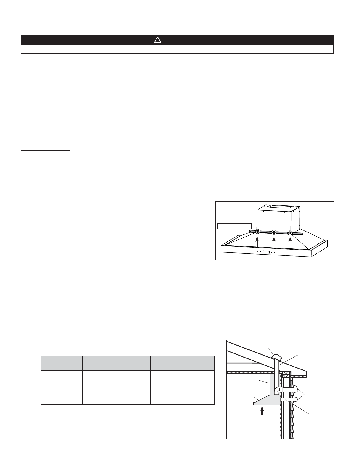
Before installation, remove and discard the shipping bracket (in grey) and its retaining
screws. See illustration on the right.
HD0942
SCREW LOCATIONS
Loading ...
Loading ...
Loading ...