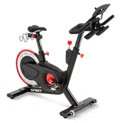

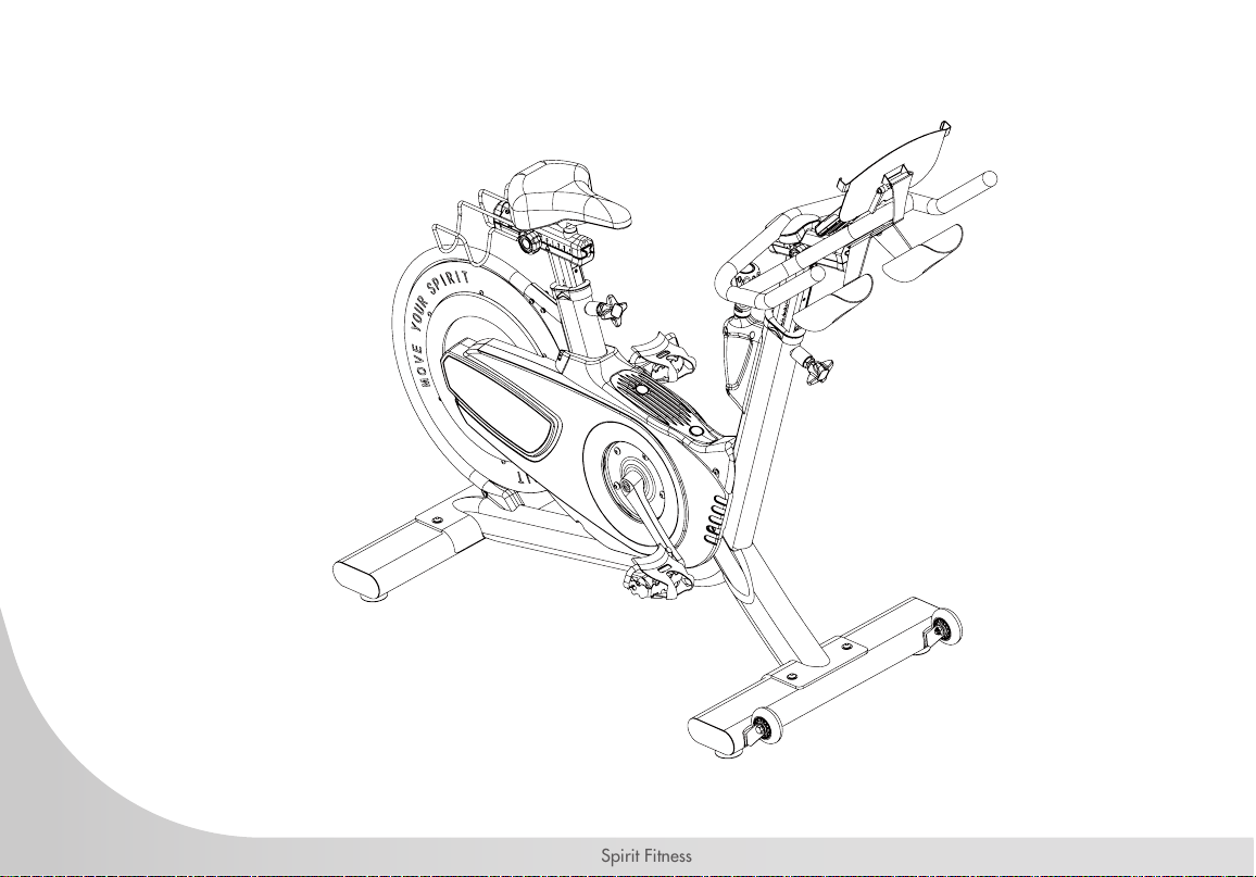
CIC850 FITNESS BIKE
OWNER’S MANUAL
Spirit Fitness
3
www.spirittness.com
TABLE OF CONTENTS
5 PRODUCT REGISTRATION
6 IMPORTANT SAFETY INSTRUCTIONS
7 IMPORTANT OPERATION INSTRUCTIONS
9 CIC850 ASSEMBLY INSTRUCTIONS
23 CONSOLE INSTRUCTIONS
30 CONNECTING TO APPS
33 GENERAL MAINTENANCE
34 TROUBLESHOOTING
36 MANUFACTURER’S LIMITED WARRANTY
39 EXPLODED DRAWING
40 PARTS LIST
Thank you for purchasing our product, please save these instructions. Please do not perform or attempt any
customizing, adjustments, repair or maintenance that is not described in this manual.
4
Spirit Fitness
Congratulations on your new Indoor Cycle and welcome to the Spirit Fitness family!
Thank you for your purchase of this quality group indoor cycle from Spirit Fitness. Your new
indoor cycle was manufactured by one of the leading tness manufacturers in the world and
is backed by one of the most comprehensive warranties available. Through your dealer, Spirit
Fitness will do all we can to make your ownership experience as pleasant as possible for
many years to come. If not purchased direct from Spirit Fitness, the local dealership where
you purchased this indoor cycle is your administrator for all Spirit Fitness warranty and service
needs. Their responsibility is to provide you with the technical knowledge and service personnel
to make your experience more informed and any difculties easier to remedy.
Please take a moment at this time to record the name of the dealer, their telephone number,
and the date of purchase below to make any future, needed contact easy. We appreciate your
support and we will always remember that you are the reason that we are in business.
Yours in Health,
Spirit Fitness
NAME OF DEALER _____________________________________
DEALER PHONE # _____________________________________
PURCHASE DATE _____________________________________
5
www.spirittness.com
RECORD YOUR SERIAL NUMBER
Please record the serial number of this tness product in the space provided below.
Serial Number:
REGISTER YOUR PURCHASE
The self-addressed product registration card must be completed in full and returned to Spirit Fitness. You can
also go to http://www.spirittness.com/warranty under the Support tab to register online.

6
Spirit Fitness
IMPORTANT SAFETY
INSTRUCTIONS
WARNING
• Use this equipment only for its intended use as
described in this manual. Do not attempt to ride this
bike at high pedal speeds until you have ridden the
bike for some time and are comfortable riding at slower
pedal speeds.
• The bike is NOT equipped with a freewheel system
which means that when the ywheel is in motion, the
pedals will be in motion. Do not attempt to stop the unit
by applying backward pressure to pedals while they
are turning as knee injury may occur. Do not attempt to
remove your feet from pedals while they are moving.
• Wait for ywheel to coast to a stop before dismounting
the bike. If you want to stop the ywheel, push down on
the resistance/brake knob.
• Serious injury or death may occur from over-training.
Consult a medical doctor or qualied tness instructor
to determine an exercise program appropriate for your
level of tness.
• Do not attempt to turn the pedal cranks by hand. Do
not touch any driving mechanism while it is in motion as
possible injury could occur.
• In a home setting, keep children away from the bike
when it is not in use. Keep children and pets away
from the unit while it is in use.
• Do not attempt to perform dip movements on
handlebars.
• Never drop or insert any object into any opening of
the bike.
• Only use the bike on a stable, level oor.
• Follow instructions for safe use of the equipment
including proper seat position, handlebar position,
and use of foot positioning system of pedals. Do not
attempt to pull up handlebar post and seat post over
the ‘MAX.’ level
• For safe operation, allow for at least 1foot (30cm) of
free space to either side of the unit and 2 feet (60cm)
of free space to the rear of the unit.
• Regularly examine the bike for damage and
wear. Inoperable components should be replaced
immediately or the equipment should not be used until
it is repaired.
• This appliance is not intended for use by persons with
reduced physical, sensory or metal capabilities, or
lack of experience and knowledge, unless they have
been given supervision or instruction concerning use of
the appliance by a person responsible for their safety.
• Keep children under the age of 13 away from
this machine.

7
www.spirittness.com
• Failure to follow all guidelines may compromise the effectiveness of the exercise experience, expose yourself (and
possibly others) to injury, and reduce the longevity
of the equipment.
• User Weight Limit: 350 lb
SAVE THESE INSTRUCTIONS - THINK SAFETY!
IMPORTANT OPERATION
INSTRUCTIONS
NEVER expose the bike to rain or moisture. This product is NOT designed for use outdoors, near a pool
or spa, or in any other high humidity environment. Maximum environmental ratings are 40-120 degrees
Fahrenheit, 95% humidity non-condensing (no water droplets forming on surfaces).
WARNING
This product can expose you to chemicals including Toluene and Acrylamide which are known to the State
of California to cause Cancer and birth defects or other reproductive harm. For more information, go to
www.P65Warnings.ca.gov
8
Spirit Fitness

9
www.spirittness.com
CIC850 PRE-ASSEMBLY
UNPACKING
1. Cut the straps, then along the dotted line on the bottom of the box;
lift the box over the unit and unpack.
2. Locate the hardware package. The hardware is separated into six
steps. Remove the tools rst. Remove the hardware for each step as
needed to avoid confusion. The numbers in the instructions that are in
parenthesis (#) are the item number from the assembly drawing
for reference.
TOOLS INCLUDED:
4mm Allen Wrench A
5mm Allen Wrench B
13/17mm Combination Wrench C
M22 Wrench D
PARTS INCLUDED:
1 Main Frame
1 Front Stabilizer
1 Rear Stabilizer
1 Adjustment Handlebar Knob
1Water Bottle Holder
1 Handlebar Post
1 Handlebar
2 Foot Pedals
1 Hardware Kit
1 Tablet Holder
1 Dumbbell Holder
1 Console Bracket
10
Spirit Fitness
CIC850 STEP ONE
3
5
65
65
5
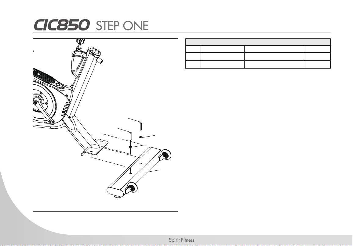
HARDWARE FOR STEP 1
PART TYPE DESCRIPTION QTY
65 SCREW
M8 X 1.25 X 55L
2
5 FLAT WASHER
M8
2
1. Gather HARDWARE FOR STEP 1.
2. Position the FRONT STABILIZER (3) on the
FRAME BRACKET as shown in the gure.
Make sure the TRANSPORT WHEELS are
facing up and toward the front of the bike.
3. Attach the STABILIZER with 2 HEX SCREWS
(65) and 2 FLAT WASHERS (5). Do not
overtighten as deformation of the stabilizer
may occur.
4. Make sure the LEVELING FEET with nut are
fully screwed into the STABILIZER.
11
www.spirittness.com
CIC850 STEP TWO
5
65
10
65
5
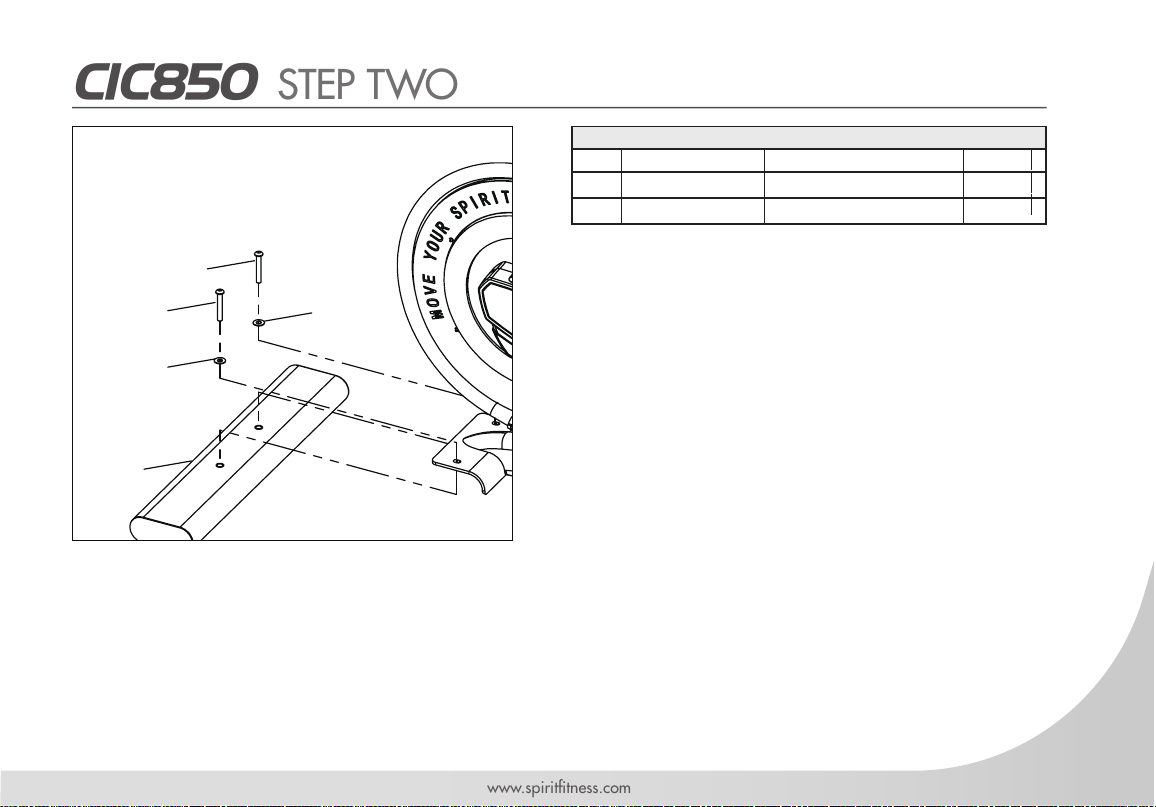
HARDWARE FOR STEP 2
PART TYPE DESCRIPTION QTY
65 SCREW
M8 X 1.25 X 55L
2
5 FLAT WASHER
M8
2
1. Gather HARDWARE FOR STEP 2.
2. Position the REAR STABILIZER (10) on the
FRAME BRACKET as shown in the gure.
3. Attach the STABILIZER with 2 HEX SCREWS
(65) and 2 FLAT WASHERS (5). Do not
overtighten as deformation of the stabilizer
may occur.
12
Spirit Fitness
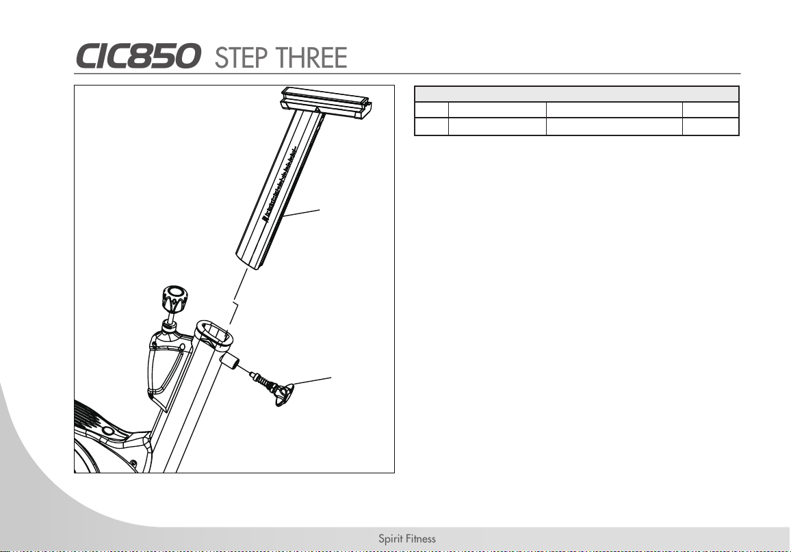
CIC850 STEP THREE
104
37
1. Remove the STAR-POP PIN (104) from the
components box and turn clockwise to tight-
en rmly into the FRAME with WRENCH
(D).
2. Insert the HANDLEBAR POST (37) into the
FRAME TUBE and tighten rmly with the
STAR-POP PIN.
HARDWARE FOR STEP 3
PART TYPE DESCRIPTION QTY
104 KNOB
STAR POP-PIN
1
13
www.spirittness.com
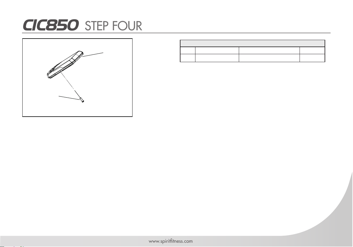
CIC850 STEP FOUR
1. Remove the pre-installed SCREW
(137) from the back of the console.
This screw will be used to secure
the console to the console bracket
later on.
HARDWARE FOR STEP 4
PART TYPE DESCRIPTION QTY
137 PHILIPS HEAD SCREW
M5*15L
1
137
110

14
Spirit Fitness
CIC850 STEP FIVE
HARDWARE FOR STEP
PART TYPE DESCRIPTION QTY
110
109
137
30
105
106
103
111
1
1
1
1
1
1
2
2
CONSOLE
CONSOLE BRACKET
SCREW
HANDLEBAR
WATER BOTTLE HOLDER
TABLET HOLDER
SCREW
FLAT WASHERS
DT-3268F
/
M5*15L
/
BLACK
BLACK
M6*P1.0*20L
M6(D16*d6.5*1.0t)
1. Remove the battery cover from the back of the
CONSOLE (110). Insert 2 AAA batteries into the
battery compartment and reinstall the battery cover.
When battery working voltage is low, the “low bat-
tery” indicator will show up on the Console display.
2. Place the CONSOLE BRACKET (109) on the
back of the console and secure it using 1 SCREW
(137) from the console box. Tighten with the Wrench (C).
3. Position the CONSOLE BRACKET (109) on the HANDLEBAR (30) making sure to align the screw holes with
ne screw holes of the Handlebar. Align the screw holes of the WATER BOTTLE HOLDER (105) with the TABLET
HOLDER (106) and the Handlebar. Secure using 2 SCREWS (103) and 2 FLAT WASHERS (111) and tighten
with the L-hex Wrench (A).
4. Pull out the SAFETY PIN(35) and slide the HANDLEBAR onto the POST (37).
110
3
106
111
111
103
103
37
35
109
137
5
15
www.spirittness.com
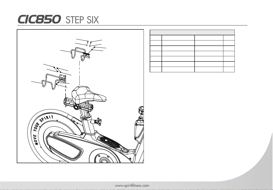
CIC850 STEP SIX
HARDWARE FOR STEP
PART TYPE DESCRIPTION QTY
35
37
1
1
SAFETY PIN
HANDLEBAR POST
/
/
27
28
113
114
6
6
1
1
Flat cross head screw
Spring Washer
Left dumbbell Holder
Right dumbbell Holder
M5*P0.8*8L
SW5*1.0t
/
/
28
27
27
28
113
114
28
27
27
28
27
28
27
28
D
1. Remove the 3 SCREWS (27) with 3
SPRING WASHERS (28) from the seat
slider assembly. Attach the LEFT DUMB-
BELL HOLDER (113) to the seat slider
and secure with 3 SCREWS (27) and 3
SPRING WASHER (28) by the Wrench
(C) tighten.
2. Repeat for the RIGHT DUMBBELL HOLD-
ER (114).
6
16
Spirit Fitness
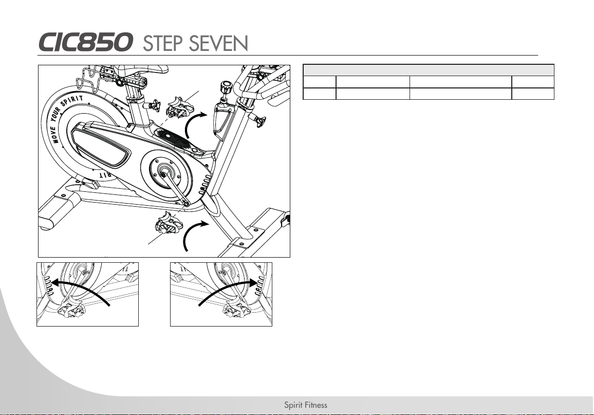
CIC850 STEP SEVEN
1. Remove pedals from the components box.
2. Look at the end of the pedal axle and notice
each pedal is marked with an R and L on
the spindle. It is indicated which side of bike
the pedal is intended to assemble.
3. Apply some grease to the threads if needed.
Locate the pedal marked “R” on the spindle
on the right side of crank (chain guard side).
Turn clockwise and tighten with the wrench
rmly.
4. Apply some grease to the threads if needed.
Locate the pedal marked “L” on the spindle
on the left side of the crank. Turn counter-
clockwise and tighten with the wrench rmly.
Left pedal assembly Right pedal assembly
135/L
136/R
HARDWARE FOR STEP 7
PART TYPE DESCRIPTION QTY
136L/R PEDAL 2
17
www.spirittness.com
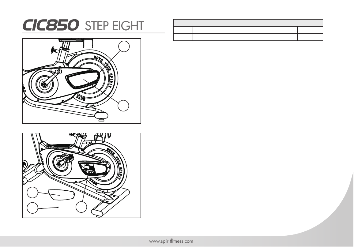
CIC850 STEP EIGHT
HARDWARE FOR STEP 8
PART TYPE DESCRIPTION QTY
119 SCREW 1
119
118
118
119
110
1. Loosen the SCREW (119) using the Wrench (C).
Remove the LEFT CHAIN GUARD B (118).
2. Insert the new battery on the sensor board.
Replace the LEFT CHAIN GUARD B (118) and
secure with the SCREW.
PAIRING THE CONSOLE AND TRANSMITTER
NOTE: ALL TRANSMITTERS ARE PAIRED WITH THE CONSOLE
BEFORE SHIPPING. THESE STEPS SHOULD ONLY NEED TO BE
USED IN CIRCUMSTANCES WHERE THE DEVICES HAVE BEEN
UNPAIRED.
1. Hold both MODE and SET keys on the console for 3
seconds.
2. On the speed transmitter, press the small “SPEED
CONTROL PAIR KEY”.
3. The console should read “0” once a successful pairing
has been established.
4. If the console reads “Err”, the pairing has failed. Press
the SET key to repeat the pairing steps again. (Note if
no action is taken within 10 seconds the console will
automatically exit pairing mode.)
18
Spirit Fitness
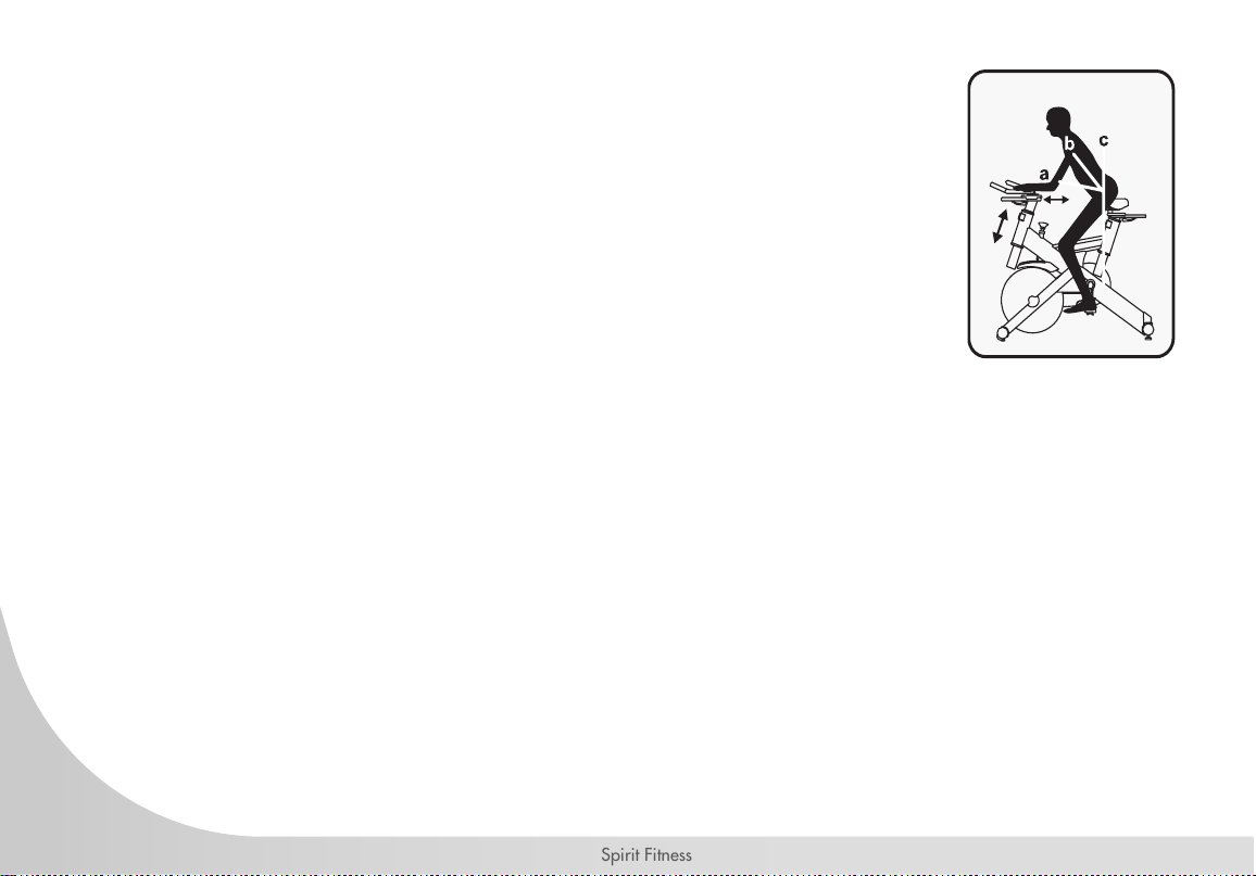
HANDLE BAR ADJUSTMENT
HANDLEBAR HEIGHT ADJUSTMENT
1. The handlebar height is a matter of preference. Start with a handlebar height that is the same
as the seat’s height. Adjusting the handlebar higher will give the rider a more upright posi-
tion; lower will result in a more crouched position.
2. Raise or lower the handlebar by loosening the knob on the handlebar post and adjust by
sliding the handlebar mount up or down as desired. Then tighten the knob to secure the han-
dlebar post. Note the nal position mark on the handlebar post for future reference.
ADJUSTMENT OF HANDLEBAR’S FORWARD/AFT POSITION
1. Loosen the knob under the handlebar and slide the handlebar forward or backward as desired. A suitable forward/aft
position should allow the rider to comfortably grasp the handlebar with a slight bend at the elbow.
2. Tighten the knob to secure the handlebar assembly.
19
www.spirittness.com
RESISTANCE ADJUSTMENT
Resistance can be adjusted easily at any time while riding to change the intensity of
workout. Turn the knob clockwise (+) to increase resistance. Turn the knob counterclockwise
(-) to decrease resistance.
EMERGENCY BRAKE
In case of emergency or before dismounting the indoor cycle, presses directly DOWN on
the resistance knob to stop the ywheel and pedal.
PEDAL STRAP ADJUSTMENT
Place the ball of you feet in the toe clip till the front of the shoe is snugly in the cage. Then
tighten the strap of toe clip around your shoe by pulling up on the strap until cage of toe
clip ts snugly around the shoe.
20
Spirit Fitness
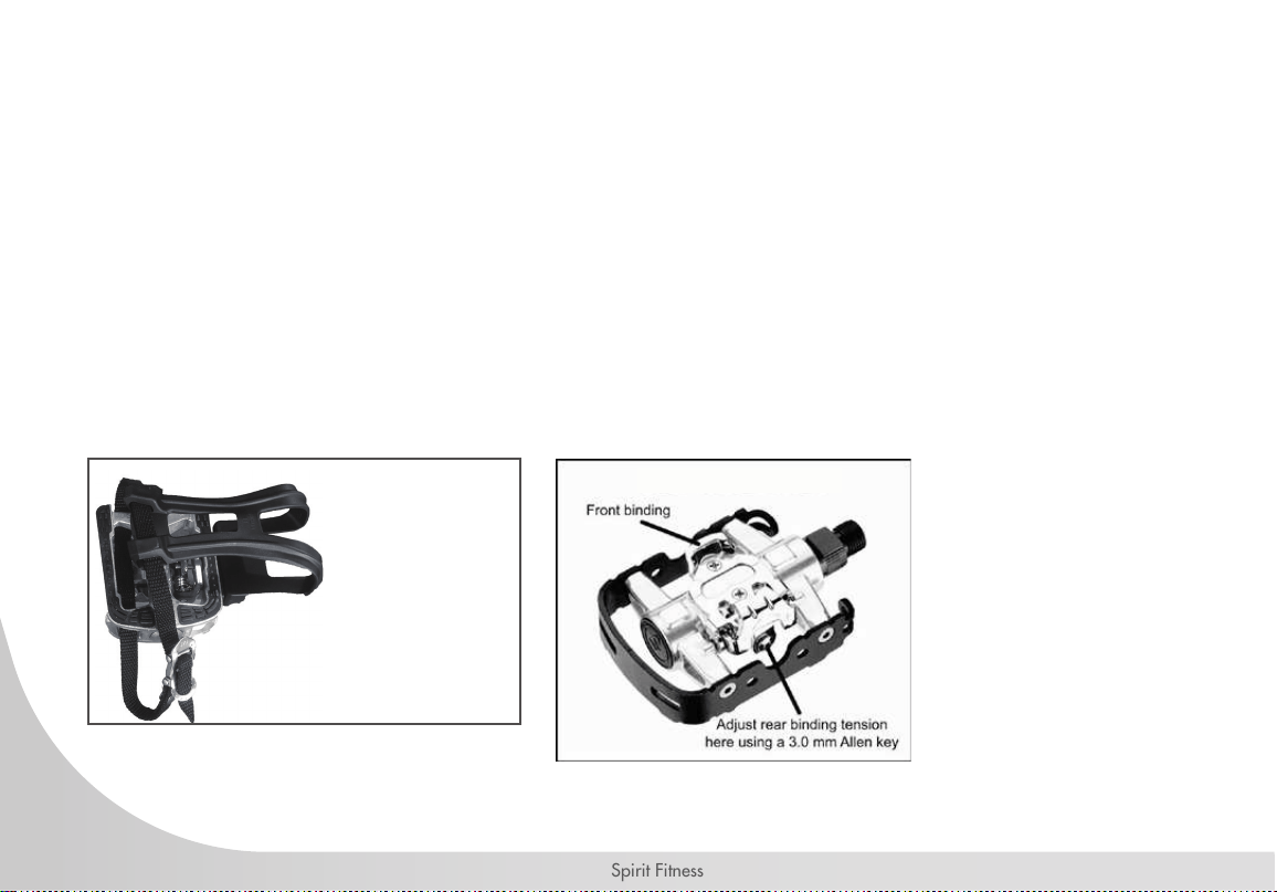
ADJUSTING THE PEDAL STRAPS
Place your feet in between the aluminum surface of the pedal and the nylon foot strap that wraps
around it. To adjust the t, pull the end of the adjustable strap down to tighten, or pull the strap up to
loosen.
USING THE SPD CLIP-IN PEDALS
Engage the clip-in pedals by placing clip-in between bindings while pushing down. Disengage by
twisting heel outwards away from exercise bike. Binding tension is adjustable and should be set so
that clip-in and shoe do not disengage when pedaling. Use an Allen key to turn tension adjusting
screws, clockwise to increase binding tension, counterclockwise to decrease binding tension.
Regular
Side View
(for use with
athletic shoes)
SPD Clip-in View

21
www.spirittness.com
BELT TENSION ADJUSTMENT
The belt tension had been set before shipping. It should not need to be adjusted when rst using. However,
you may need to make the minor tension adjustment over time.
NOTE: Make sure you adjust both sides equally - either tighten or loosen the belt tension so that the
ywheel maintains alignment with the frame.
ADJUST THE BELT TENSION
1. Remove the 2 Guard (Top) Cover (No. 47) on the Guard (top) (No. 46). Remove the
4 Screws (No. 50) and 2 Screws (No. 51). Remove the Guard (top) (No. 46).
2. Remove the 7 Screws (No. 50) and remove the Right guard (No. 44).
3. Use L type wrench (B) to loosen 2 Hex Screws (No. 55) with two turns
counterclockwise.
4. Use L type wrench (B) to adjust Screw (No. 17). Turn counter-clockwise to loosen belt.
Turn clockwise to tighten belt. Then adjust the belt. Tighten the 2 Hex Screws (No. 55)
clockwise.
5. Turn the crank to see if belt runs smoothly. You can also try riding the bike to test the
belt tension. If there is still a problem, repeat step #4 until belt is at correct tension.
6. Put the Right guard (No. 44) back on and re-tighten the Screws (No. 50). Put the
Guard (top) (No. 46) back on and re-tighten the 4 Screws (No. 50) and 2 Screws
(No. 51).
51
1755
50
51
5050
50
46
47

22
Spirit Fitness
INDOOR CYCLE SETUP
LEVELERS
Place the cycle on a level area, if at all possible. If the cycle needs leveling, turn the levelers clockwise or
counterclockwise until the base is stable and does not rock.
ADJUSTMENT KNOBS
All four adjustment levers function the same way. Turn the knob clockwise to tighten and counterclockwise
to loosen.
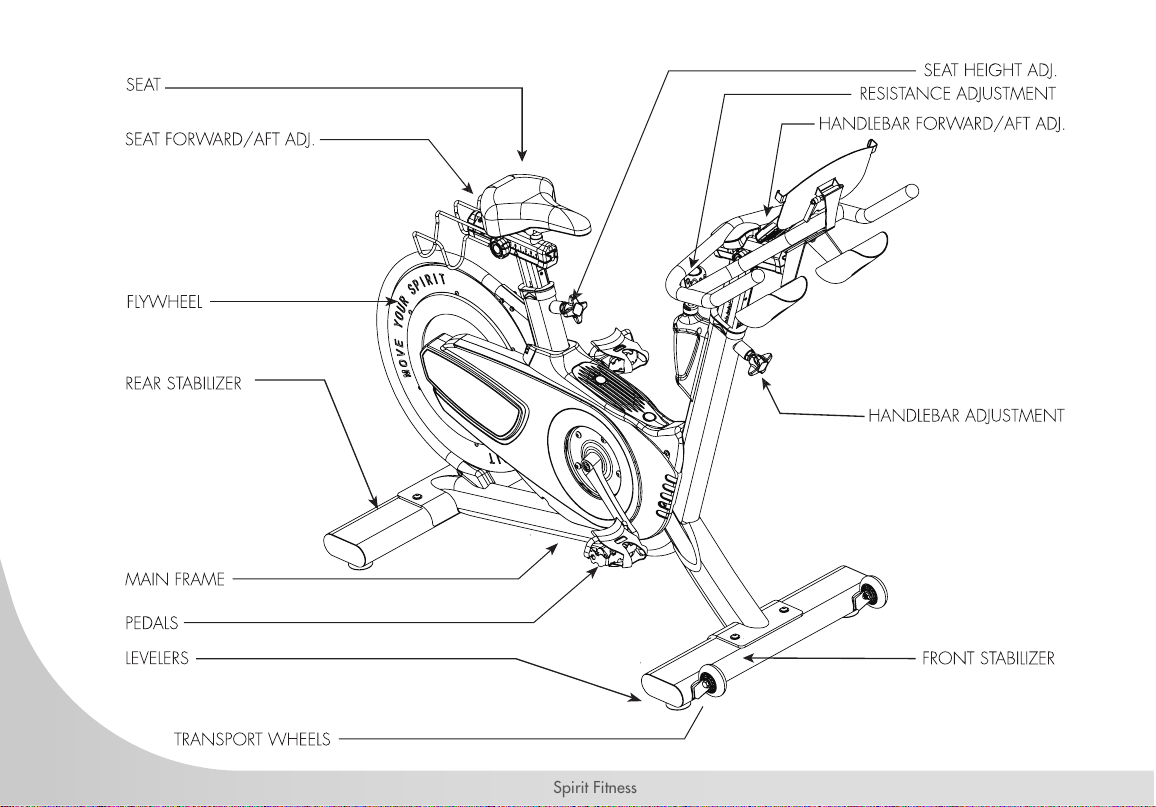
SEAT
The pitch of the saddle can be adjusted to accommodate all users. Loosen the horizontal bolt under the seat to
adjust the pitch, then retighten.
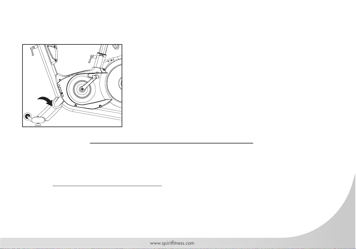
TRANSPORTATION
The indoor cycle is equipped with two transport wheels, which are engaged when the rear of the CIC850
indoor cycle is lifted.

23
www.spirittness.com
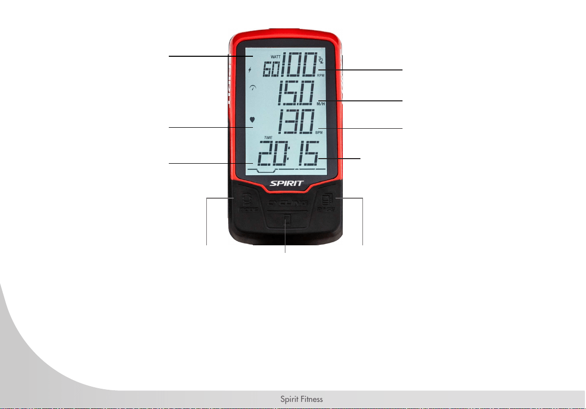
CIC850 CONSOLE OPERATION
24
Spirit Fitness
Cadence Bar Graphic: 0 - 199RPM
RPM: 0 - 199RPM
SPEED: 0 - 99 KM/H
PULSE: 30 - 240BPM
TIME: Count Down Range 1 - 99 Minutes
Count Up Range 00:01 - 99:59
Protocol: BLE4.0
RPM
SPEED
HEART RATE
WATTS
LOW BATTERY
MODE
PAGE/ RECORD
SMARTPHONE
BUTTON
BPM
TIME
DISTANCE
KCAL

25
www.spirittness.com
TIME
Time is the length of time (min. / sec.) The time will count up or count down during user peddling.
When peddling stopped, the time will stop to count up or count down after 3 seconds.
CADENCE & SPEED
Cadence is the measurement of how fast the cranks are rotating in RPM’s. The approximate speed of
the bike can also be display (MPH/KPH) in the section. In addition to the MPH/KPH, the CADENCE
will also display a bar graph that allows the rider to keep track of the approximate cadence that
has been achieved. Average Cadence or Speed will be automatically shown after the rider stop the
pedaling for 3 seconds.
DISTANCE
Distance is the measurement of the approximate distance achieved on the bike. This distance is based
on the user riding a bike with tires that are the same size as the bikes ywheel.
KCAL
Kcal is the approximation of calories burned during your work out. The calories are calculated by
measuring the rider’s instantaneous heart rate, age, and weight.
HEART RATE (apply to HR featured models only)
This is the approximation of heart rate detect from the chest belt during the work out. Average Heart
Rate will be automatically shown after 3 seconds if the console cannot detect the current Heart Rate.
26
Spirit Fitness
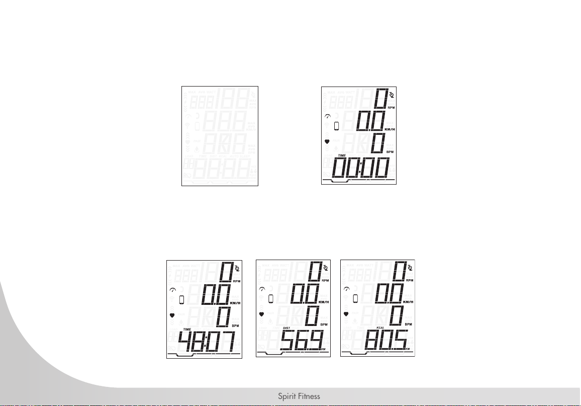
QUICK START
In Power Saving Mode, Press Page Key will bring the CONSOLE to ‘QUICK Start’ active state.
MODE SELECT
Press ‘MODE’ key to select the TIME, DIST, KCAL display.
Power Saving Mode Quick Start Mode

27
www.spirittness.com
RESETTING ALL MEASURED VALUE
To clear all the measured values, press and hold the Page key under the TIME Mode for 3 seconds.
All the measured value for AVG SPEED, AVG PULSE, TIME, DIST, KCAL will reset to zero.
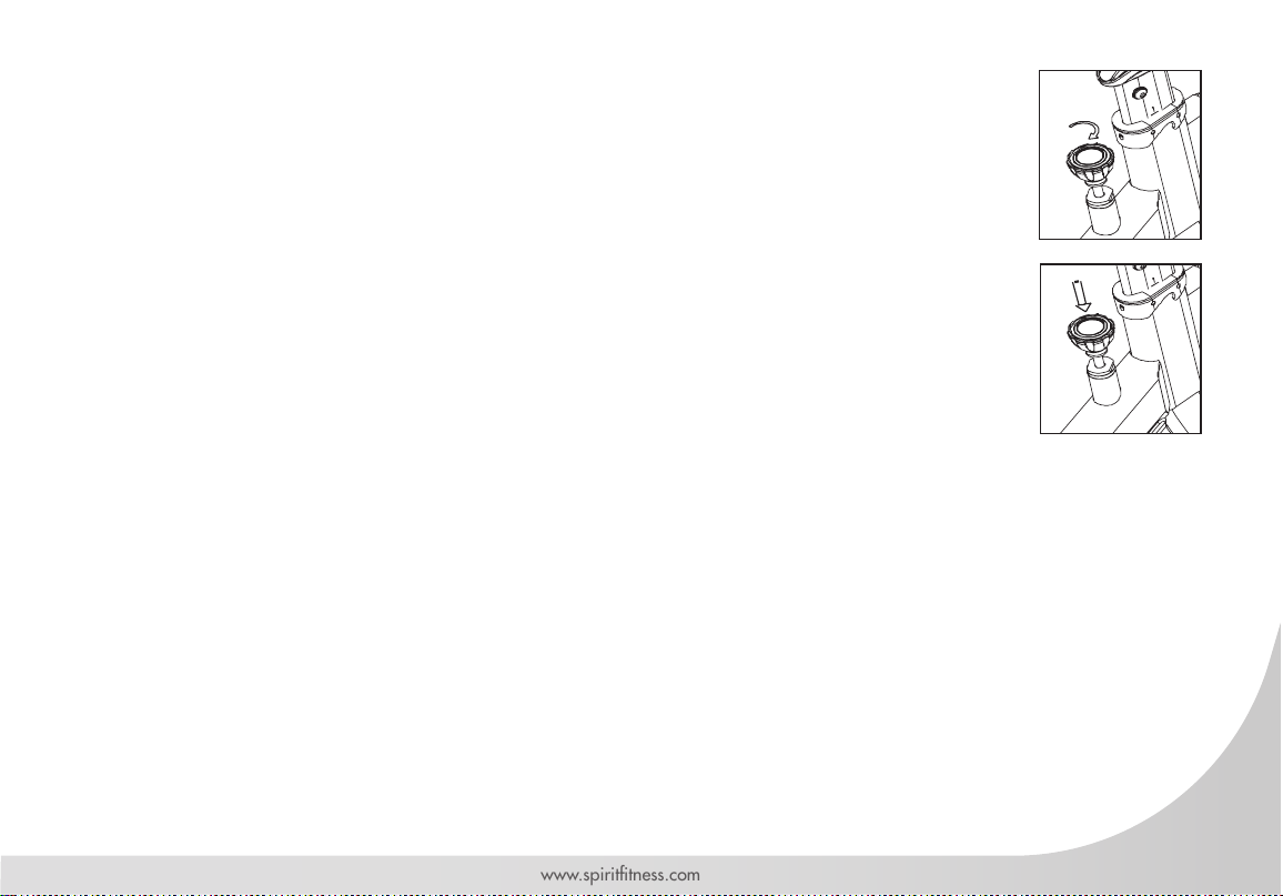
TIMER SETTING
The TIMER displays users’ exercise-workout time. Set the count down time by holding the “Page”
button down for 3 seconds. Press “Page” again to continue. Now, press the “Mode” button until the
desired time is displayed. If the user does not set the COUNT DOWN TIME, the TIME will count up
from 00:00 to 99:59.
If user prior set the COUNT DOWN TIME, the TIME will count down to zero with ashing display
and Alarm automatically from counting down to counting up from 00:01. The user can go into TIMER
setting from SPEED or DISTANCE Mode by press and hold ‘SET’ key for 3 seconds.
CHANGING BETWEEN METRIC AND IMPERIAL
Hold the PAGE button for 3 seconds until the display starts ashing with TIME displayed. Press the
PAGE button to select KG or LB (metric or imperial). Press MODE to conrm your selection.
28
Spirit Fitness
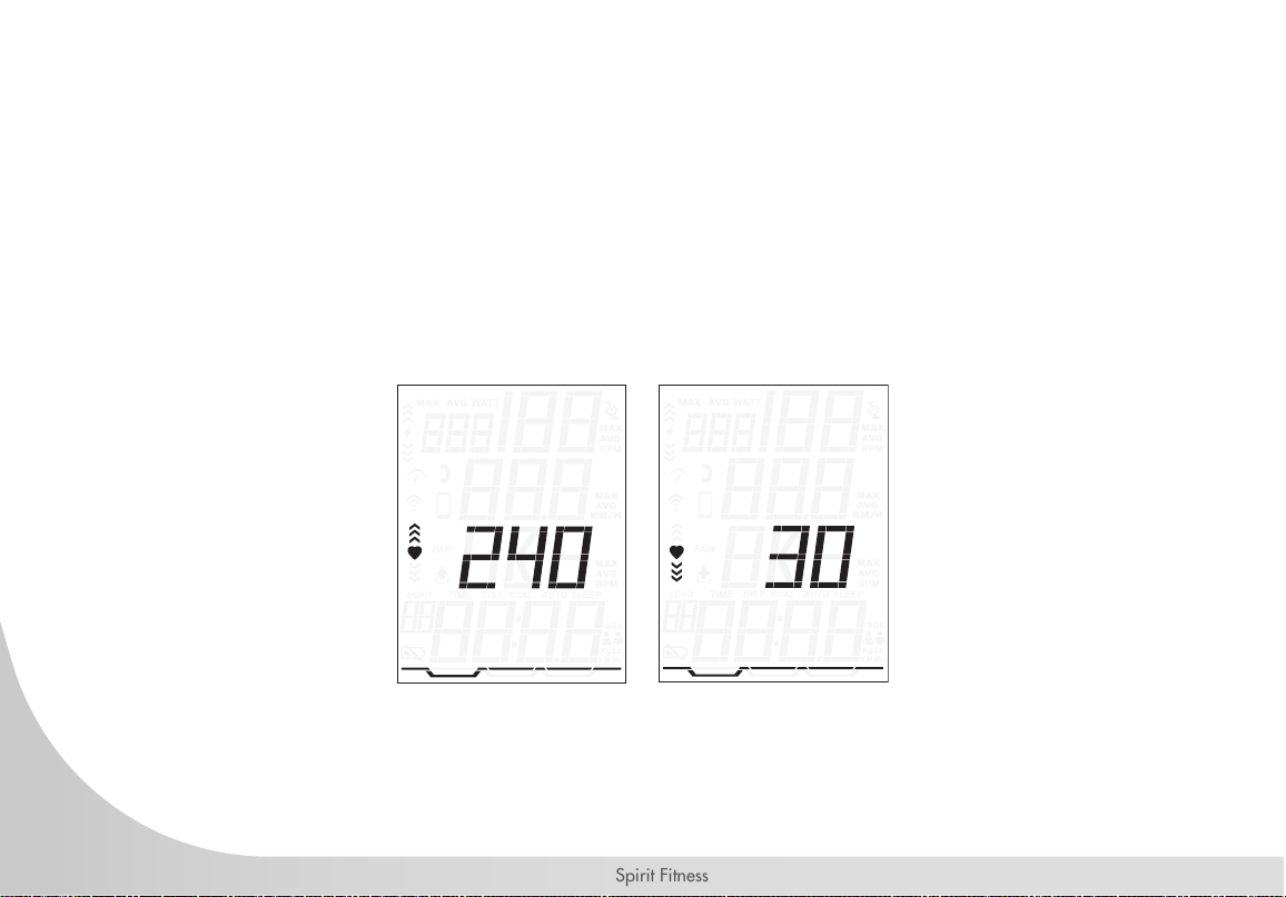
HEART RATE TARGET ZONES
Under the DIST or KCAL, hold the Page Key for 3 seconds to go into the settings. Press MODE to go
to the heart rate icon then press Page to go to the heart rate target zone window.
Press the MODE key to increase the maximum heart rate limit. After setting the maximum heart rate,
press the Page key to adjust the minimum heart rate.

29
www.spirittness.com
PERSONAL DATA SETTINGS
Accurate personal data will make your calories
burned more accurate. Under KCAL or DISTANCE
MODE, Hold Page key for 3 seconds to go into
the setting, continually press ‘MODE’ key to get to
the heart rate windows.
1. Press the Page key to select the gender, either:
Male / Female
2. Press the Page key to go to the weight unit
setting. Press the Mode key to select the
weight, either: Kg. / Lb.
Note: this change of metric units to imperial
units will affect the displaying units: MPH/
KPH, Lb/KG and ML/KM.
3. Press the Page key, this will go to the weight
setting. Press the Mode key to increase the
weight by 0.5 Kg. or 0.5Lb.
1. Press the smart phone key on the console.
2. On your phone, open the desired app and search for devices to pair.
3. Select the bike console once it is shown on your device. The app and bike console should now
be paired.
BLUETOOTH PAIRING
PAIRING THE CONSOLE AND
TRANSMITTER
NOTE: ALL TRANSMITTERS ARE PAIRED WITH THE CONSOLE
BEFORE SHIPPING. THESE STEPS SHOULD ONLY NEED TO BE
USED IN CIRCUMSTANCES WHERE THE DEVICES HAVE BEEN
UNPAIRED.
1. Hold both MODE and SET keys on the console for 3
seconds.
2. On the speed transmitter, press the small “SPEED
CONTROL PAIR KEY”.
3. The console should read “0” once a successful pairing
has been established.
4. If the console reads “Err”, the pairing has failed. Press
the SET key to repeat the pairing steps again. (Note if
no action is taken within 10 seconds the console will
automatically exit pairing mode.)
30
Spirit Fitness
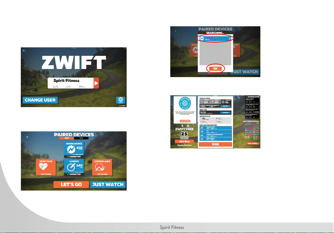
CONNECTING TO ZWIFT
1. Log in to Zwift.
2. Select the power source and cadence, the
system will prompt you to select machine.
3.
4. Select ride to start
5. Enjoy the ride!
31
www.spirittness.com
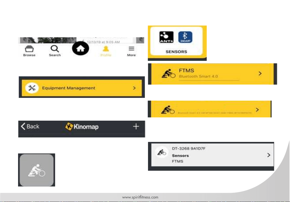
1. Select “More” on the bottom right corner
2. Select equipment management
3. Select “+” on the top right corner
4. Select exercise bike
5. Select “sensor” at the very bottom
6. Select machine you wish to connect
7. Successfully paired machine will show up on
this page
CONNECTING TO KINOMAP
SPIRIT BIKE
32
Spirit Fitness
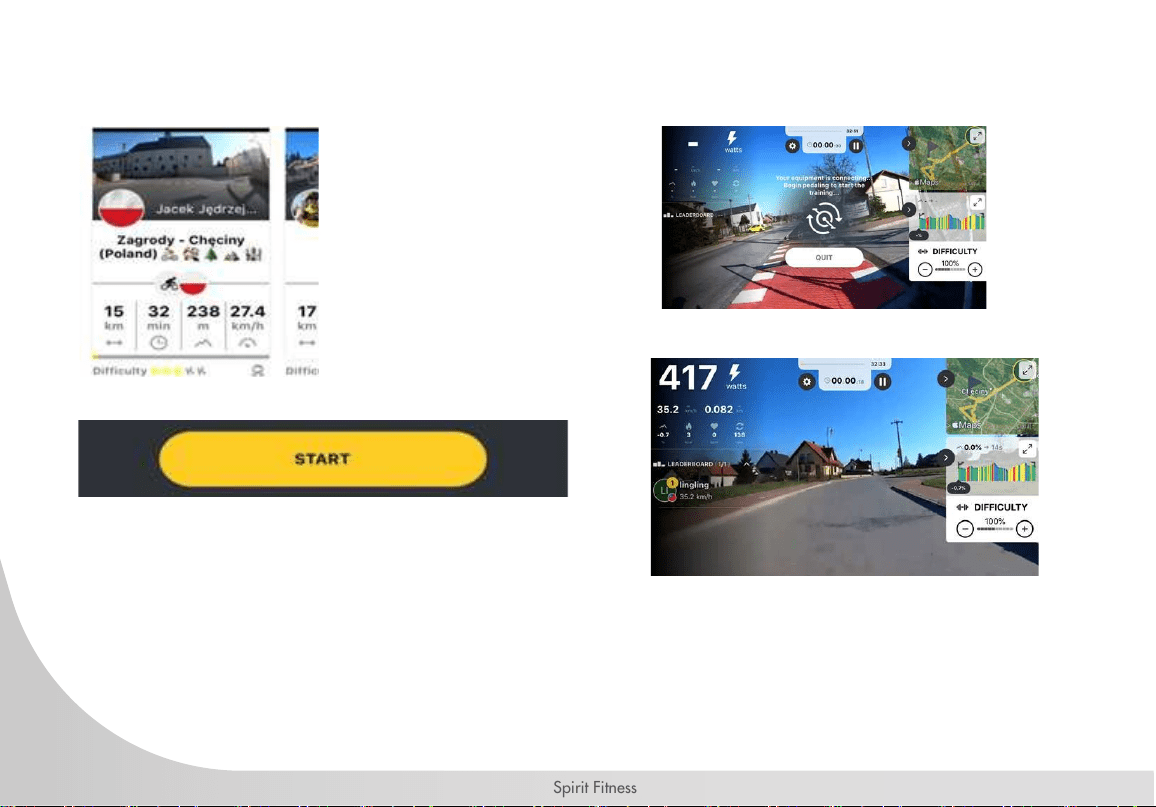
8. Go to browse to select a video you would
like to play
9. Select Start
10. Press start on the console when kinomap
ask you to start pedaling
11. Enjoy the ride!
The console is compatible with most virtual
active apps available.

33
www.spirittness.com
GENERAL MAINTENANCE
1. Wipe down all areas in the sweat path with a damp cloth after each workout.
2. If a squeak, thump, clicking or rough feeling develops the main cause is most likely one of two reasons:
a. The hardware was not sufciently tightened during assembly. All bolts that were installed
during assembly need to be tightened as much as possible. It may be necessary to use a larger wrench than the one
provided if you cannot tighten the bolts sufciently. We cannot stress this point enough; 90% of calls to the service
department for noise issues can be traced to loose hardware.
b. The crank arm nut needs to be retightened.
c. If squeaks or other noises persist, check that the unit is properly leveled. There are 2 leveling pads on the bottom of the
rear stabilizer, use a 14mm wrench (or adjustable wrench) to adjust the levelers.
SANITIZING YOUR SPIRIT FITNESS EQUIPMENT
• Unupholstered high-contact surfaces (hard plastics) can be sanitized using a 75% isopropyl alcohol solution and a
clean, dry cloth.Spray surfaces to be sanitized, and use the dry cloth to wipe clean. Allow surfaces to dry before
using.
• For upholstered or soft-plastic surfaces, use a conditioner after sanitizing.Be sure to follow the instructions provided
by the conditioner manufacturer to ensure proper use of the conditioner.
• Alternatively, you can make your own spray by mixing the proper ratio of isopropyl alcohol and distilled water to
reach a 75% solution.
• For more details on sanitization, or to learn how to make your own spray solution, please visit https://support.
spirittness.com/hc/en-us/articles/4406787148564 .

34
Spirit Fitness
MAINTENANCE SCHEDULE
1. Do not service internal parts of pedals. If they are found to be worn internally, we recommend replacing the pedal.
2. Use of lubricants or cleaning solutions other than those so specied will result in diminished performance and a
shorter life span for that part.
Part Recommended Action Frequency Cleaner
Pedals Ensure that pedals are tight in crank arms,
that all screws on pedals are tight, and that
the pedal straps are not frayed.
Before each Use N/A
Frame Wipe down using a clean, soft damp cloth Daily Water
Flywheel Wipe down using a clean, soft damp cloth Weekly Water
Brake Pad Check for wear Monthly N/A

35
www.spirittness.com
TROUBLESHOOTING
No Display on Console
1. Press any key to bring the console to ‘Quick Start’
mode.
2. Ensure that the batteries are installed properly in
the Console and Transmitter. If they are, install
fresh batteries.
No Heart Rate signal displayed
1. Ensure that your chest strap is worn correctly, and
that there is moisture under the electrodes of the
chest strap.
2. Relocate the bike away from any equipment that
could potentially interrupt the radio frequency
signal, such as a DVD player or television, etc.
RPM or HR does not change
1. Press ‘MODE key’ repeatedly to toggle between
SPEED (SPD), DISTANCE (DIST), TIME (TIME) and
CLOCK (CLK) values.
2. Press and Hold ‘SET key’ repeatedly to clear past
measured value or go into setting and exit.
Cadence number jumps high or low
1. Separate bikes that may be paired to the same
console code and are cross-talking, or simply run
transmitter pair stage again on the bike.
2. Relocate the bike to a different part of the room,
away from any RF interference areas.
Heart Rate signal gets interrupted or drops out
1. Ensure that there is a minimum distance of 36
inches between bikes.
2. Verify that your chest strap is secure and that the
electrodes are making contact with your chest at
all times.
CONSOLE BATTERY INSTALLATION:
1. Remove the battery cover from the back of the
computer.
2. Insert 2 AAA batteries into the battery com-
partment and reinstall the battery cover.
3. When battery voltage is low, the ‘Low bat-
tery’ indicator will show up on the Console
display.

36
Spirit Fitness
INDOOR CYCLE WARRANTY – EFFECTIVE NOVEMBER 08, 2021
Spirit Fitness warrants all its Indoor Cycle parts for a period of time listed below from the date of retail sale, as
determined by sale receipt, or in the absence of a sales receipt eighteen (18) months from the original factory
shipping date. Spirit Fitness’ responsibilities include providing new or remanufactured parts, at Spirit Fitness’
option, and technical support to our independent dealers and servicing organizations. In the absence of a
dealer or service organization, these warranties will be administered by Spirit Fitness directly to a consumer.
The warranty period applies to the following components:
*Wear Items include items such as grips, end caps, and toe cage straps.
NORMAL RESPONSIBILITIES OF THE CONSUMER
1. The warranty registration card must be completed and returned to the address listed on the card within 10 days of
the original purchase, or completed online to validate the manufacturer’s limited warranty.
2. Proper use of the tness equipment in accordance with the instructions provided in this manual.
3. Expenses for making the tness equipment accessible for servicing, including any item that was not part of the
tness equipment at the time it was shipped from the factory.
4. Damages to the tness equipment nish during shipping, installation or following installation.
5. Routine maintenance of this unit as specied in this manual.
Warranty
Commercial
Commercial
Residential
Frame
10 Years
15 Years
Lifetime
Parts
3 Years
3 Years
3 Years
Labor
1 Year
1 Year
1 Year
Console & Wear Items*
1 Year
1 Year
1 Year
(Health Clubs, YMCA, Community Centers, dues paying facilities)
(non-dues paying facilities)
*Prisons and correctional facilities are excluded from warranty coverage.

37
www.spirittness.com
EXCLUSIONS
This warranty does not cover the following:
1. CONSEQUENTIAL, COLLATERAL, OR INCIDENTAL DAMAGES SUCH AS PROPERTY DAMAGE AND
INCIDENTAL EXPENSES RESULTING FROM ANY BREACH OF THIS WRITTEN OR ANY IMPLIED WARRANTY.
Note: Some states do not allow the exclusion or limitation of incidental or consequential damages, so this
limitation or exclusion may not apply to you.
2. Service call reimbursement to the consumer. Service call reimbursement to the dealer that does not involve
malfunction or defects in workmanship or material, for units that are beyond the warranty period, for units that
are beyond the service call reimbursement period, for tness equipment not requiring component replacement, or
tness equipment not in non-dues paying facility or household use.
3. Damages caused by services performed by persons other than authorized Spirit Fitness service companies; use of
parts other than original Spirit Fitness parts; or external causes such as corrosion, discoloration of paint or plastic,
alterations, modications, abuse, misuse, accident, improper maintenance, inadequate power supply, or acts of
God.
4. Products with original serial numbers that have been removed or altered.
5. Products that have been: sold, transferred, bartered, or given to a third party.
6. Products that do not have a warranty registration card on le at Spirit Fitness. Spirit Fitness reserves the right to
request proof of purchase if no warranty record exists for the product.
7. THIS WARRANTY IS EXPRESSLY IN LIEU OF ALL OTHER WARRANTIES EXPRESSED OR IMPLIED, INCLUDING
THE WARRANTIES OF MERCHANTABILITY AND/OR FITNESS FOR A PARTICULAR PURPOSE.
8. Product used in prisons and correctional facilities
9. Warranties outside of the United States may vary. Please contact your local dealer for details.

38
Spirit Fitness
SERVICE
Keep your bill of sale. Twelve (12) months from the date on the bill of sale or eighteen (18) months from the date
of factory shipping as determined by the serial number establishes the labor warranty period should service be
required. If service is performed, it is in your best interest to obtain and keep all receipts. This written warranty
gives you specic legal rights. You may also have other rights that vary from state to state. Service under this
warranty must be obtained by following these steps, in order:
1. Contact your selling authorized Spirit Fitness dealer. OR
2. Contact your local authorized Spirit Fitness service organization.
3. If there is a question as to where to obtain service, contact our service department at (870) 935-1107.
4. Spirit Fitness’ obligation under this warranty is limited to repairing or replacing, at Spirit Fitness’ option, the product
through one of our authorized service centers. All repairs must be preauthorized by Spirit Fitness. If the product is shipped
to a service center freight charges to and from the service center will be the customer’s responsibility. For replacement
parts shipped while the product is under warranty, the customer will be responsible for shipping and handling charges.
For in-home service, the customer will be responsible for a trip charge. There will be an additional trip charge if the
customer is located over 100 miles from the nearest service center.
5. The owner is responsible for adequate packaging upon return to Spirit Fitness. Spirit Fitness is not responsible for
damages in shipping. Make all freight damage claims with the appropriate freight carrier. DO NOT SHIP ANY UNIT
TO OUR FACTORY WITHOUT A RETURN AUTHORIZATION NUMBER. All units arriving without a return authorization
number will be refused.
6. For any further information, or to contact our service department by mail, send your correspondence to:
SPIRIT FITNESS, INC.
P.O. Box 2037
Jonesboro, AR 72402-2037
Product features or specications as described or illustrated are subject to change without notice. All warranties are made by Spirit Manufacturing, Inc.
This warranty applies only in the 48 contiguous United States. NOTE: This does not apply to Alaska or Hawaii.
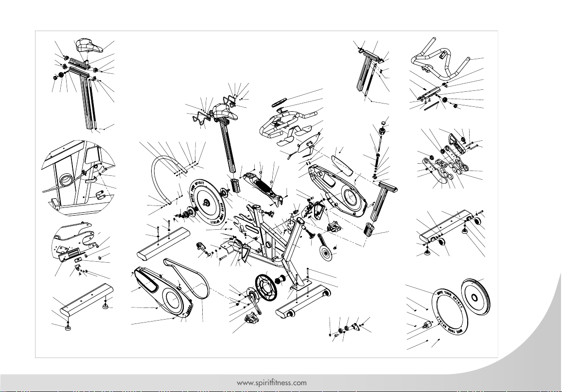
39
www.spirittness.com
52
46
49
136R
48
51
50
52
135L
65
5
120 59
125 12379
112
97
22
96
99
98
102
87
100
101
83
84
86
112
12528128
2
28
128
125
124
81
80
129
5
1
127
125
121
103
5
125
125
125 28 128
125
125
28
128
107
130
88
90
89
125
125
125
125 125
125
125
125
125
111
111
128
128
28
28
125
65
65
5
125
125
122122
125
125
126
126
88
103
65
5
46
46
46
46
27
27
27
27
28
28
28
28
46
46
53
54
55
56
56
57
58
63
66
69 568
85
92
93
91
91
94
94
95
104
104
105
106
108
109
110
111
113
114
115
116
117
118 119
27
27
133
134
134
28
2827
27
26 39
41
37
38
40
26
25
41
25
35
34
2631
32
36
33
19
20
23
22
21
26
36
30
5
8
4
9
7
5
8
7
9
5
5
6 6
4
3
9
8
10 8
9
45
43
45
45 45
45
45
42
44
47
78 72 26
76
74
73
71
77
75
26
76
72
72
77
71
71
71 71 71
29
24
11
13
16
18
1412
17
15
26
19 23 20
22
21
25
25
26
26
26
131
132
82
4660616162
64 67
5
26 25 25 27
57
57
57
70
110 110

40
Spirit Fitness
CIC850 PARTS LIST
No. DESCRIPTION QTY
1 Frame 1
2 Outer circle tube assembly 1
3 Front stabilizer assembly 1
4 Transportation wheel 2
5 Flat washer SUS304 M8(D19*d8.5*1.0t) 8
6 Nylon nut SUS304 M8*P1.25 2
7 Hex screw M8*1.25*45L 2
8 Hex nut 3/8"*16T*8t 4
9 Leveler foot 4
10 Rear stabilizer assembly 1
11 Seat slider welding assembly 1
12 Seat post assembly 1
13 Seat adjustment taut block 1
14 Seat post panel 1
15 Up sweat guard(back) 1
16 Up sweat guard(front) 1
17 Down sweat guard(back) 1
18 Down sweat guard(front) 1
19 Adjustable knob 2
20 Konb screw (UCP)9*27.5L 2
21 Brake knob--cover 2
22 Flat cross head screw (UCP)M4*P0.7*10L 3
23 Knob bolt block 2
24 Pop pin knob( short) 1
25 Flat cross head screw SUS304 M3*P0.5*6L 6
26 Flat cross head screw SUS304 M4*P0.7*8L 11
27 Flat cross head screw M5*P0.8*8L 9
28 Spring Washer SW5*1.0t 12
29 Saddle 1
30 Handlebar 1
31 Adjustment handlebar block(up) 1
32 Up sweat guard(front) (wider) 1
33 Up sweat guard(back) (wider) 1
34 Handlebar adjustment taut block 1
35 Pop pin knob(long) 1
36 Flat hex screw SUS304 M8*P1.25*25L 2
37 Handlebar Post assembly 1
38 Down sweat guard(front) (wider) 1
39 Down sweat guard(back) (wider) 1
40 Handlebar post panel 1
41 Flat cross head screw SUS304 M8*P1.25*12L 2
42 Flywheel set 1
43 Aluminum Ring 1
44 Flywheel AXIS 1
45 Flat cross head screw SUS304 M5*P0.8*16L 6
46 Flat cross head screw M8*P1.25*10L 8
47 Permanent magnet 1
48 Sprocket / pulley 1
49 Right crank 1
50 Left crank 1
51 Bottom bracket set 1
52 Crank x screw 2
53 Small sprocket / pulley 1
54 Bearing block (left) 1
55 Bearing block (right) 1
56 Bearing 16004ZZ 2
57 Flat cross head screw SUS304 M6*P1.0*12L 6
58 Flat washer UCP D24*d8.5*1.5t 1

41
www.spirittness.com
59 Belt 5PK 1360L 1
60 Idler pulley arm assembly 1
61 Bearing-6203ZZ 2
62 C type clip 1
63 Idler pully adjust screw 1
64 Idler pully positioning nut 1
65 Flat cross head screw SUS304 M8*P1.25*55L 4
66 Flat washer M8(D16*d8.2*1.0t) 3
67 Idler pully casing 1
68 Flywheel Fixed sheet casing A 1
69 Flywheel Fixed sheet Positioning nut 1
70 Sensor board xing piece 1
71 Permanent magnet 6
72 Bearing-LF-1910ZZ 3
73 Brake block (right) 1
74 Brake block (left) 1
75 Brake gasket assembly 1
76 Flat cross head screw SUS304 M4*P0.7*40L 2
77 Nylon nut SUS304 M4*P0.7 2
78 Brake line Turntable 1
79 Brake block axis 1
80 Brake block axis Lining 1
81 Brake Spring 1
82 Brake line 1
83 PE Wahser 1
84 Nylon nut SUS304 M8*P2.0 1
85 Slider block 1
86 Nylon nut SUS304 M5*P0.8 1
87 Fixed pulley 1
88 Nylon bushing (black) 2
89 Handbrake shaft pin L 1
90 E type circlip 5 1
91 E type circlip 3 2
92 Swing arm assembly 1
93 Nylon xed pulley 1
94 Handbrake shaft pin B 2
95 Extension spring 1
96 Brake Knob 1
97 Brake knob up cover 1
98 Brake knob cover 1
99 Brake rod 1
100 Compression spring 1
101 Square plastic bushing 1
102 Flat washer SUS304 M8(D16*d8.1*1.6t) 1
103 Flat cross head screw SUS304 M6*P1.0*20L 2
104 Star-type pop pin knob 2
105 Water bottle holder 1
106 Tablet Holder 1
107 Fixed base assembly 1
108 L type knob 1
109 Console bracket 1
110 Console DT-3268F 1
111 Flat washer SUS304 M6(D16*d6.5*1.0t) 2
112 Bushing (seat post/handlebar) 2
113 Left dumbbell Holder 1
114 Right dumbbell Holder 1
115 Outside plate xing part backing plate 1
116 Outside plate xing 1
117 Left chain guard A 1
118 Left chain guard B 1

42
Spirit Fitness
119 Flat cross head screw M4*P0.7*10L 1
120 Right chain guard B 1
121 Chian guard up 1
122 Chian guard up cover 2
123 Brake guard right 1
124 Brake guard left 1
125 Flat cross head screw M5*P0.8*14L 25
126 Flat cross head screw M5*P0.8*25L 2
127 Round head Phillips tapping screws 1
128 Flat washer M5(5.3*10*1t) 6
129 Nylon nut SUS304 M10*P1.5 1
130 Flat washer (D16*d10.2*1.0t) 1
131 Hex screw M6*P1.0*20L 1
132 Hex nuts (UCP)M6*P1.0*5.0t 1
133 Hex nuts (UCP)M16*P1.5*7.8t 1
134 Flat cross head screw M8*P1.25*15L 2
135
/136
Pedal L/R 1
137 Screw M5*15L 1

43
www.spirittness.com

800.258.4555
spiritservice@spirittness.com
www.spirittness.com
Spirit Fitness
3000 Nestle Road
Jonesboro, AR 72401
CIC850 Owners Manual
© 2021 All Rights Reserved
Revision 5: 05.05.2022