
- 1
Please read and comply with
these original instructions prior
to the initial operation of your appliance and
store them for later use or subsequent own-
ers.
Your sales outlet should be informed about
any transit damage noted when unpacking
the product.
– Warning and information plates on the
machine provide important directions
for safe operation.
– In addition to the information contained
in the operating instructions, all statuto-
ry safety and accident prevention regu-
lations must be observed.
Notes about the ingredients (REACH)
You will find current information about the
ingredients at:
www.kaercher.com/REACH
The warranty terms published by the rele-
vant sales company are applicable in each
country. We will repair potential failures of
your appliance within the warranty period
free of charge, provided that such failure is
caused by faulty material or defects in man-
ufacturing. In the event of a warranty claim
please contact your dealer or the nearest
authorized Customer Service centre.
Please submit the proof of purchase.
DANGER
To avoid risks, all repairs and replacement
of spare parts may only be carried out by
authorized customer service personnel.
– Only use accessories and spare parts
which have been approved by the man-
ufacturer. The exclusive use of original
accessories and original spare parts
ensures that the appliance can be oper-
ated safely and trouble free.
– For information about accessories and
spare parts, please visit www.kaerch-
er.com.
DANGER
Warns about immediate danger which can
lead to severe injuries or death.
WARNING
Warns about possible danger which could
lead to severe injuries or death.
CAUTION
Points out a possibly dangerous situation
which can lead to light injuries or property
damage.
Use this sweeper only as directed in these
operating instructions.
– This sweeper has been designed to
sweep dirt and debris from outdoor sur-
faces.
– The machine is not suitable for being
driven on public roads.
– Any use extending beyond this is not
considered as proper use. The manu-
facturer is not liable for any losses re-
sulting from this; the user alone bears
the risk for this.
– It is not allowed to use this appliance in-
doors.
– The machine may not be modified.
– The machine is only suitable for use on
the types of surfaces specified in the
operating instructions.
– The machine may only be operated on
the surfaces approved by the company
or its authorised representatives.
– The following applies in general: Keep
highly-flammable substances away
from the appliance (danger of explo-
sion/fire).
– Never vacuum up explosive liquids,
combustible gases or undiluted acids
and solvents. This includes petrol, paint
thinner or heating oil which can gener-
ate explosive fumes or mixtures upon
contact with the suction air. Acetone,
undiluted acids and solvents must also
be avoided as they can harm the mate-
rials on the machine.
– Never sweep/vacuum up reactive metal
dusts (e.g. aluminium, magnesium,
zinc), as they form explosive gases
when they come in contact with highly
alkaline or acidic detergents.
– The appliance is not suitable for sweep-
ing off hazardous substances.
– Do not sweep/vacuum up any burning
or glowing objects.
– The machine may not be used or stored
in hazardous areas. It is not allowed to
use the appliance in hazardous loca-
tions.
– It is strictly prohibited to take co-pas-
sengers.
– Pushing/pulling or transporting objects
by means of this appliance is prohibit-
ed.
– Asphalt
– Industrial floor
– Screed
– Concrete
– Paving stones
Contents
Contents . . . . . . . . . . . . . . . . . EN 1
General notes . . . . . . . . . . . . . EN 1
Proper use . . . . . . . . . . . . . . . . EN 1
Safety instructions . . . . . . . . . . EN 2
Function. . . . . . . . . . . . . . . . . . EN 2
Operating and Functional Ele-
ments. . . . . . . . . . . . . . . . . . . . EN 3
Before Startup . . . . . . . . . . . . . EN 3
Start up . . . . . . . . . . . . . . . . . . EN 4
Operation. . . . . . . . . . . . . . . . . EN 4
Shutdown. . . . . . . . . . . . . . . . . EN 6
Care and maintenance . . . . . . EN 6
Troubleshooting. . . . . . . . . . . . EN 12
Technical specifications. . . . . . EN 13
EU Declaration of Conformity . EN 14
Accessories . . . . . . . . . . . . . . . EN 14
General notes
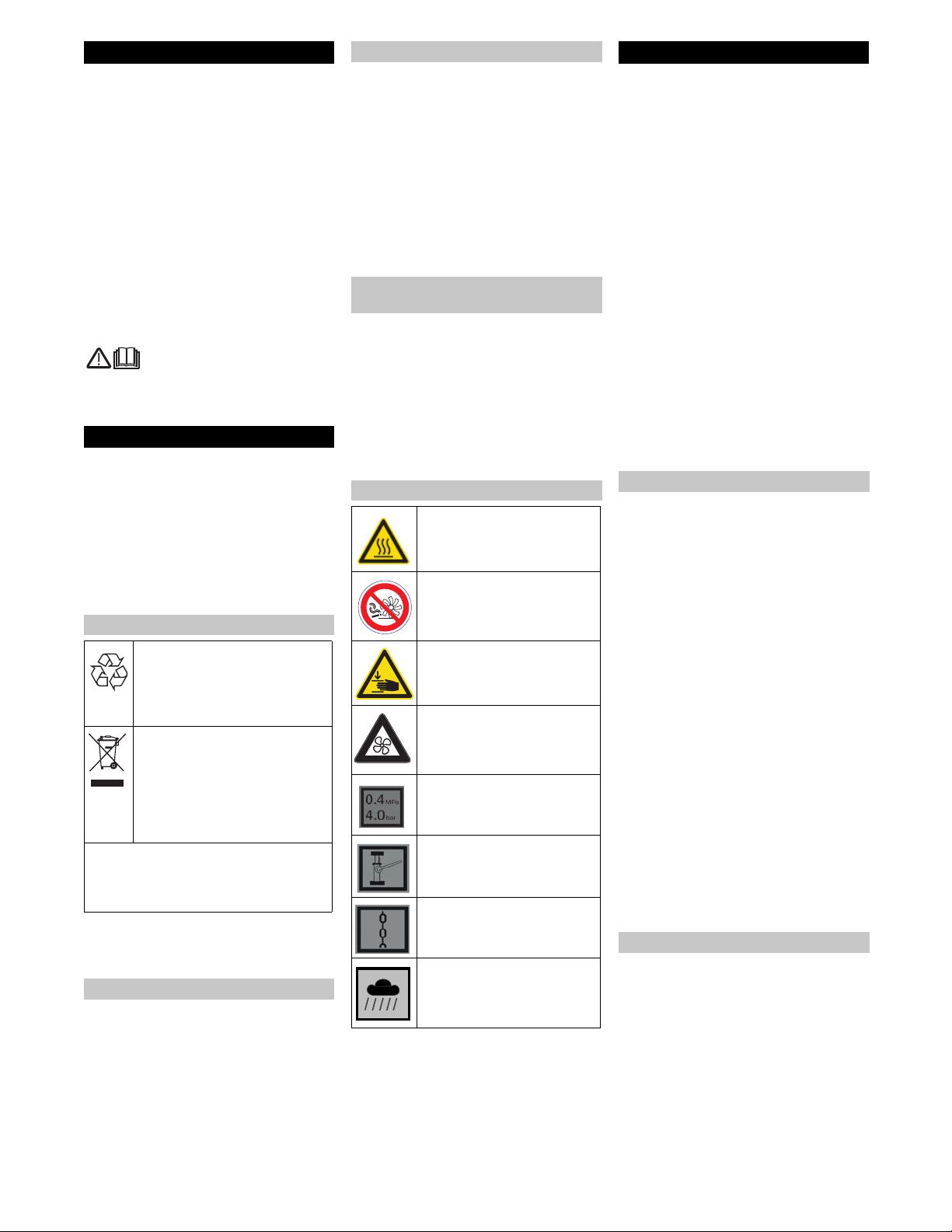
Environmental protection
The packaging material can be
recycled. Please do not throw the
packaging material into house-
hold waste; please send it for re-
cycling.
Old appliances contain valuable
materials that can be recycled.
Please arrange for the proper re-
cycling of old appliances. Please
dispose your old appliances us-
ing appropriate collection sys-
tems.
Please do not release engine oil, fuel oil,
diesel and petrol into the environment
Protect the ground and dispose of used oil
in an environmentally-clean manner.
Warranty
Accessories and Spare Parts
Symbols in the operating
instructions
Symbols on the machine
Risk of burns on account of hot
surfaces!
Please do not sweep away any
burning substances such as
cigarettes, match sticks or sim-
ilar objects.
Risk of being squeezed or hurt
at the belts, side-brushes, con-
tainers, machine cover.
The air inlets next to the driv-
er's seat must not be covered.
Do not store any objects next
to or behind the seat.
Tyre pressure
Intake points for the jack
Lashing point
Wet/dry flap
Proper use
Foreseeable misuse
Suitable surfaces
17EN

- 2
– The machine with working equipment
must be checked to ensure that it is in
proper working order and is operating
safely prior to use. Otherwise, the appli-
ance must not be used.
– If the appliance is used in hazardous ar-
eas (e.g. filling stations) the corre-
sponding safety provisions must be ob-
served. It is not allowed to use the ap-
pliance in hazardous locations.
– The operator must use the appliance
properly. The person must consider the
local conditions and must pay attention
to third parties, in particular children,
when working with the appliance.
– Prior to starting work, the operator must
ensure that all protective devices are
properly installed and function correct-
ly.
– The operator of the appliance is liable
for accidents with other individuals or
their property.
– Ensure that the operator wears tight-fit-
ting clothes. Wear sturdy shoes and
avoid wearing loose-fitting clothes.
– Check the immediate vicinity prior to
starting (e.g. children). Ensure suffi-
cient visibility!
– Never leave the machine unattended
so long as the engine is running. The
operator may leave the machine only
when the engine has come to a stand-
still, the machine has been protected
against accidental movement, if neces-
sary, by applying the immobilization
brake and the ignition key has been re-
moved.
– The appliance may only be used by per-
sons who have been instructed in han-
dling the appliance or have proven
qualification and expertise in operating
the appliance or have been explicitly
assigned the task of handling the appli-
ance.
– This appliance is not intended for use
by persons (including children) with lim-
ited physical, sensoric or mental capac-
ities or lack of experience and/or skills,
unless such persons are accompanied
and supervised by a person in charge of
their safety or if they received precise
instructions on the use of this appli-
ance.
– Children should be supervised to pre-
vent them from playing with the appli-
ance.
Danger
Risk of injury!
Danger of tipping if gradient is too high.
– The falling and rising gradients in the di-
rection of travel may not exceed 18%.
Danger of tipping on unstable ground.
– Only use the machine on sound surfac-
es.
Danger of tipping with excessive sideways
tilt.
– The gradient perpendicular to the direc-
tion of travel should not exceed 15%.
Danger
Risk of injury!
– Please follow the special safety instruc-
tions in the Operating Instructions Man-
ual for petrol engine devices.
– Do not close the exhaust.
– Do not bend over the exhaust or touch
it (risk of burns).
– Do not touch the drive motor (risk of
burns).
– Ensure that there is adequate ventila-
tion or provision for diverting the ex-
haust gas while operating the appliance
in closed rooms (risk of poisoning).
– Exhaust gases are poisonous and haz-
ardous to health, do not inhale them.
– The engine requires approx. 3-4 sec-
onds to come to a standstill once it has
been switched off. During this time, stay
well clear of the working area.
– The engine is to be brought to a stand-
still and the appliance is to be fastened
properly during transportation.
– Switch off the appliance and remove
the ignition key prior to performing any
cleaning or maintenance tasks on the
appliance, replacing parts or switching
over to another function.
– Always disconnect the battery when
working on the electrics.
– Do not clean the appliance with a water
hose or high-pressure water jet (danger
of short circuits or other damage).
– Maintenance work may only be carried
out by approved customer service out-
lets or experts in this field who are famil-
iar with the respective safety regula-
tions.
– Please observe the local safety regula-
tions regarding portable commercially
used appliances.
– Always use appropriate gloves while
working on the device.
The sweeper operates using the overthrow
principle.
– The side brushes (3) clean the corners
and edges of the surface, moving dirt
and debris into the path of the roller
brush.
– The rotating roller brush (4) moves the
dirt and debris directly into the waste
container (5).
– The dust raised in the container is sep-
arated by the dust filter (2) and the fil-
tered clean air is drawn off by the suc-
tion fan (1).
– The cleaning of the dust filter (2) takes
place automatically.
Safety instructions
General notes on safety
Safety instructions concerning the
operation
Safety information concerning the
driving operation
Safety information concerning the
combustion engine
Safety information concerning the
transport of the appliance
Safety information concerning
maintenance and care
Function
1 2
3
5 4
18 EN
- 3
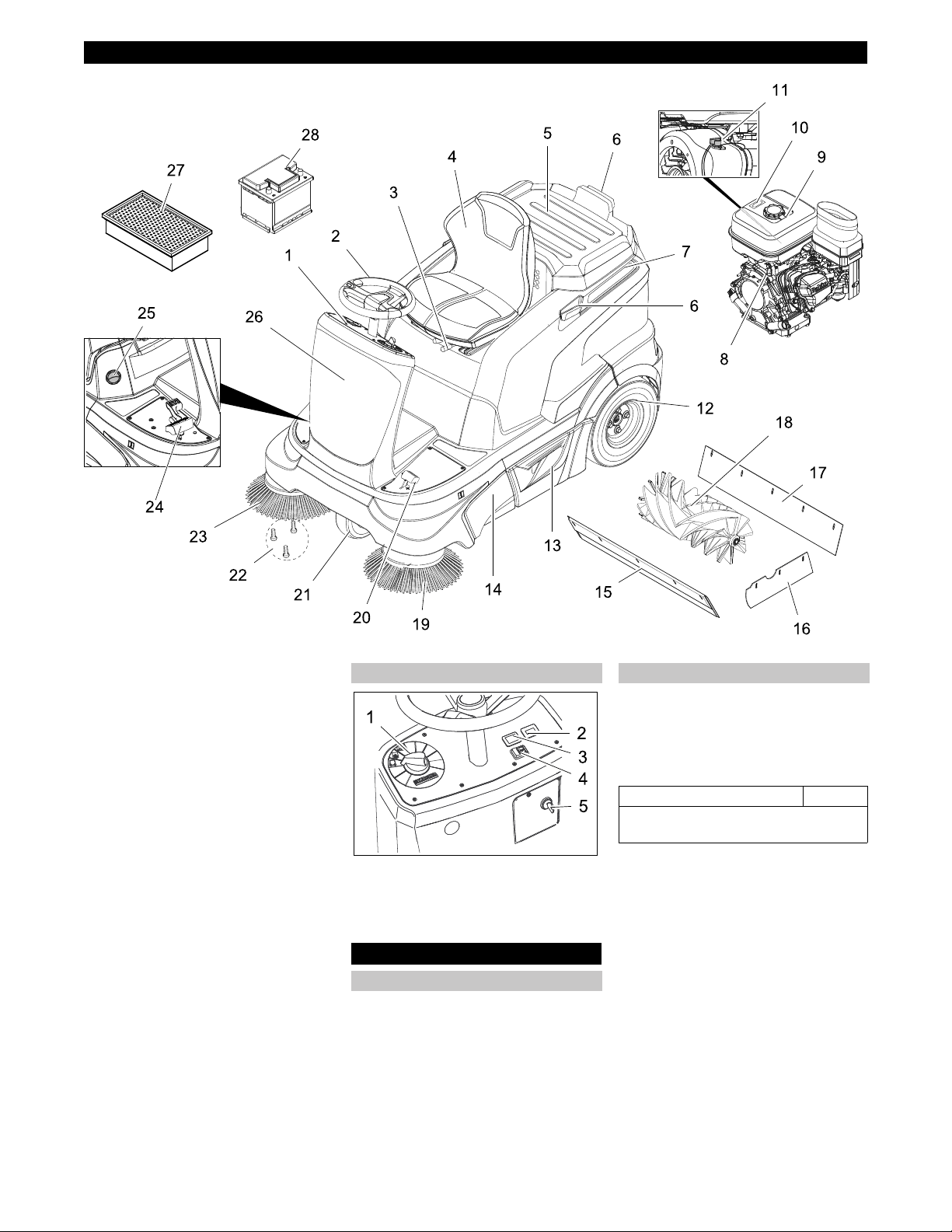
1 Operating field
2 Steering wheel
3 Lever for seat adjustment
4 Seat (with seat contact switch)
5 Storage area
6 Holding rail for home base
7 Cover
8 Petrol engine
9 Fuel tank
10 Tank indicator
11 Stop switch
12 Rear wheel
13 Waste container (both sides)
14 Roller brush access
15 Front sealing strip
16 Side sealing strip
17 Rear sealing strip
18 Roller brush
19 Left side brush (optional)
20 Pedal for raising/lowering bulk waste
flap
21 Front wheel
22 Fastener of the side brush
23 Right side brush
24 Drive pedal
25 Wet/dry flap
26 Fuses (behind front panel)
27 Dust filter (flat-fold filter)
28 Maintenance-free batteries
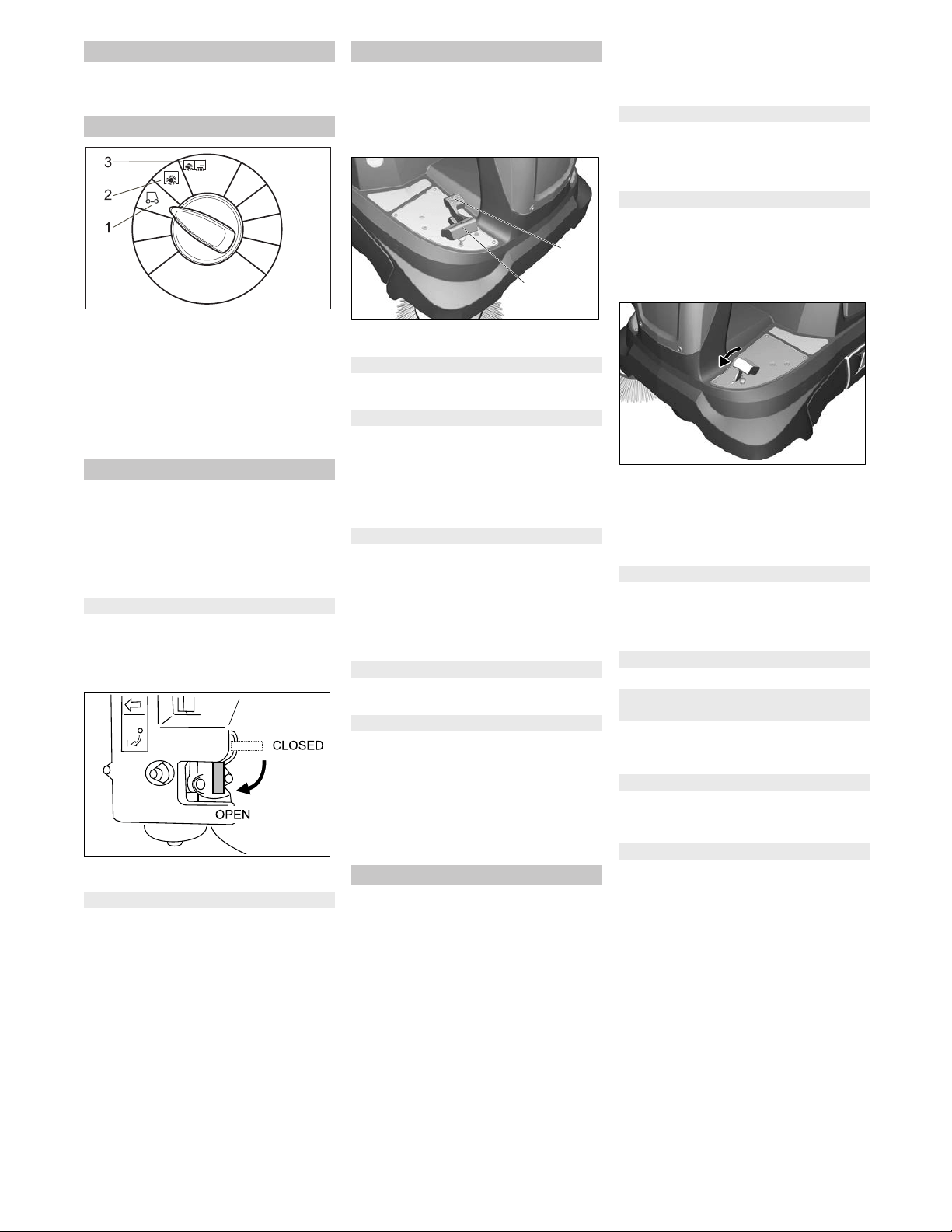
1 Programme switch
2 Operating hour counter
3 Not assigned
4 Horn
5 Ignition key
DANGER
Danger of crushing while closing the ma-
chine cover. Hence, lower the machine
cover slowly.
Prior to commissioning, maintenance or
adjustment tasks, the appliance cover must
be opened.
Grab the front of the appliance cover
and fold it back together with the seat.
A retaining band keeps the appliance
cover in the rear position.
Danger
Risk of injury, risk of damage!
Observe the weight of the appliance when
you load it!
Do not use a forklift truck to unload the ma-
chine as this may damage it.
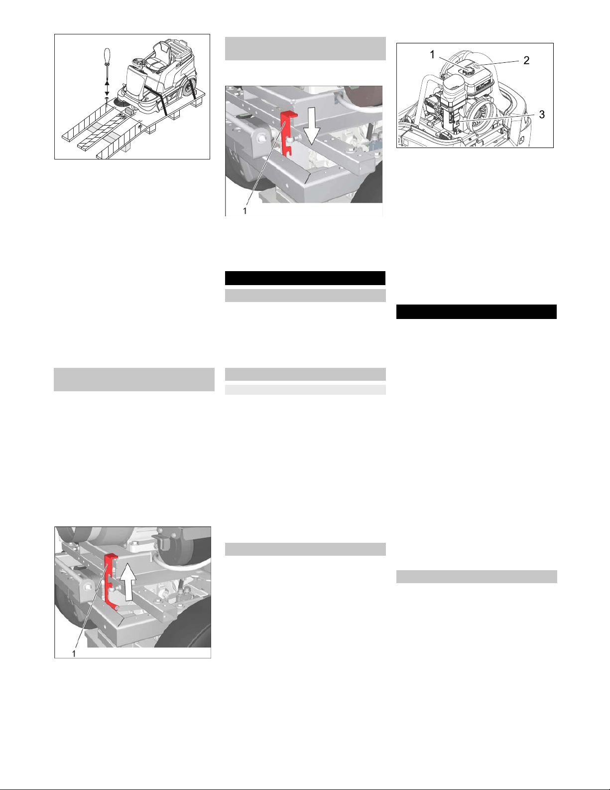
Use a suitable ramp or a crane to load
the appliance!
If the machine is delivered on a pallet,
you must create an unloading ramp us-
ing the boards provided.
To unload the machine, proceed as follows:
Cut plastic packing belt and remove foil.
Connect battery (see section on Care
and maintenance)
Remove the elastic tape fasteners at
the stop points.
Operating and Functional Elements
Operating field
Before Startup
Open/ close device hood
Unloading tips
Net weight (transport weight) 265 kg *
* If upgrade kits are installed, the weight is
respectively higher.
19EN
- 4
Four indicated floor boards of the pallet
are fastened with screws. Unscrew
these boards.
Place the boards on the edge of the pal-
let. Place the boards in such a way that
they lie in front of the four wheels of the
machine. Fasten the boards with
screws.
Slide the four support beams included
in the packaging under the ramp.
Remove the wooden blocks used for ar-
resting the wheels and slide them under
the ramp.
Slide the machine over the prepared
ramp from the pallet.
The machine can be moved in 2 ways:
(1) By pushing it (see Moving sweeper
without engaging self-propulsion).
(2) By driving it (see Moving sweeper by
engaging self-propulsion).
Danger
Risk of injury! Before engaging the free-
wheel operation, the machine must be se-
cured to prevent it rolling away.
– The travel drive is inoperable.
– Braking effect exists no more.
CAUTION
Risk of damage to the hydrostatic axle
drive!
Only push sweeper slowly and across short
distances.
Open the device hood.
Position of the freewheel lever up - appli-
ance can be pushed.
Engage the freewheel lever in the upper
position.
Note: If the freewheel lever does not
lock in, then slightly move the machine
forward and backward.
After moving the appliance, snap the
freewheel lever into the lower position.
Close cover.
Open the device hood.
Position freewheel lever down - appliance
is ready to start.
Engage the freewheel lever in the lower
position.
Close cover.
Note: The machine has been fitted with an
automatic parking brake that is activated as
soon as the engine is switched off and the
driver leaves his seat.
Park the sweeper on an even surface.
Remove ignition key.
Check engine oil level.
Check the filling level of the fuel tank at
the fuel gauge.
Check fill level of hydraulic oil.
Check side brush.
Check the roller brush for wear and
wrapped belts.
Empty waste container.
Check tyre pressure.
Check function of seat contact switch.
Check, if the stop switch on the com-
bustion engine is in the "ON" position.
Note: For description, see section on Care
and maintenance.
Danger
Risk of explosion!
– Only fuel up while motor is turned off.
– Only use the fuels specified in the Op-
erations Manual.
– Do not refuel the machine in enclosed
spaces.
– Smoking and naked flames are strictly
prohibited.
– Ensure that no fuel reaches the hot
open surfaces.
1 Tank lid
2 Tank indicator
3 Fuel cock
Switch off engine.
Open the device hood.
Read the filling level at the fuel gauge.
The red area indicates the filling level.
Open fuel filler cap.
Use and install a funnel with a filter.
Use "regular unleaded petrol".
Tank
filling with empty tank approx. 5 li-
tre
Wipe off any spilt fuel, remove funnel
and close fuel filler cap.
Close cover.
CAUTION
Risk of damage to the drive! Prior to each
run, ensure that the freewheel lever is in the
lower position.
CAUTION
The air inlets next to the driver's seat must
not be covered. Do not store any objects
next to or behind the seat.
WARNING
Long hours of using the appliance can
cause circulation problems in the hands on
account of vibrations.
It is not possible to specify a generally valid
operation time, since this depends on sev-
eral factors:
– Proneness to blood circulation deficien-
cies (cold, numb fingers).
– A firm grip impedes blood circulation.
– Continuous operation is worse than an
operation interrupted by pauses.
In case of regular, long-term operation of
the device and in case of repeated occur-
rence of the symptoms (e.g. cold, numb fin-
gers) please consult a physician.
Pull seat adjustment lever inwards.
Slide seat, release lever and lock in
place.
Check that the seat is properly locked in
position by attempting to move it back-
wards and forwards.
Moving sweeper without engaging
self-propulsion
Moving sweeper by engaging self-
propulsion
Start up
General notes
Prior to start/safety test
Maintenance Works
Refuelling
Operation
Adjusting driver's seat
20 EN
- 5
Note: The max. load of the storage area is
20 kg.
Ensure safe fastening of the cargo.
1 Driving
Driving to the Place of Use.
Side brush and roller brush are raised.
2 Sweeping with sweep roller
Roller brush is lowered.
3 Sweeping using roller brush and
side brushes
Roller brush and side brushes are low-
ered.
Note: The machine is equipped with a seat
contact switch If the driver's seat is vacat-
ed, the machine is switched off.
Note: If the seat contact switch has
switched off the machine, then turn the ig-
nition key to "0" to prevent battery dis-
charge.
Open the device hood.
Check, if the stop switch on the com-
bustion engine is in the "ON" position.
Open the fuel supply.
Close cover.
Sit on the driver's seat.
Do NOT press the accelerator pedal.
Set programme switch to step 1 (driv-
ing).
Turn ignition key past position 1.
If the machine starts, release the igni-
tion key.
Note: Never operate the starter motor for
longer than 10 seconds. Wait at least 10
seconds before operating the starter motor
again.
CAUTION
Always press the accelerator pedal careful-
ly and slowly. Do not jerkily change from re-
verse to forward drive or vice versa.
1 Accelerator pedal, "forwards"
2 Accelerator pedal, "reverse"
Press slowly the accelerator pedal "for-
ward".
Danger
Risk of injury! While reversing, ensure that
there is nobody in the way, ask them to
move if somebody is around.
Press slowly the accelerator pedal "re-
verse".
– The accelerator pedal can be used to
vary the driving speed infinitely.
– Avoid pressing the pedal suddenly as
this may damage the hydraulic system.
– In the event of power loss on inclined
surfaces, slightly reduce the pressure
on the accelerator pedal.
Release the accelerator pedal, the ma-
chine brakes automatically and stops.
CAUTION
Objects or loose obstacles may not be run
over or pushed.
Stationary obstacles of up to 5 cm can
be run over slowly and carefully.
Stationary obstacles of more than 5 cm
may only be run over using a suitable
ramp.
Danger
Risk of injury! If the bulk waste flap is open,
stones or gravel may be flung forwards by
the roller brush. Make sure that this does
not endanger persons, animals or objects.
CAUTION
Do not sweep up packing strips, wire or
similar objects as this may damage the
sweeping mechanism.
CAUTION
To avoid damaging the floor, do not contin-
ue to operate the sweeping machine in the
same position.
Note: To achieve an optimum cleaning re-
sult, the driving speed should be adjusted
to take specific situations into account.
Note: During operation, the waste contain-
er should be emptied at regular intervals.
Note: When cleaning surfaces, only lower
the roller brush.
Note: Also lower side brush when cleaning
along edges.
Set programme switch to step 2. Roller
brush is lowered.
Note: Roller brush starts operating auto-
matically.
Note: To sweep up larger items up to a
height of 50 mm, e.g. cigarette packs, the
bulk waste flap must be raised briefly.
Raising bulk waste flap:
Press the pedal for the bulk waste flap
forwards and keep pressed down.
To lower it, take foot off pedal.
Note: An optimum cleaning result can
only be achieved if the bulk waste flap
has been lowered completely.
Set programme switch to step 3. Side
brushes and roller brush are lowered.
Note:
Roller brush and side brush start
operating automatically.
Close wet/dry flap
Open wet/dry flap.
Note: You can thus prevent the filter
system from getting blocked.
Open wet/dry flap.
Note: This protects the filter from mois-
ture.
The appliance is equipped with an auto-
matic filter cleaning system.
The cleaning takes place automatically ap-
prox. every 15 seconds. In the process a
short blow-off sound can be heard.
Check the installed dust filter for con-
tamination every once in a while. Re-
place a heavily contaminated or defec-
tive filter.
Storage area
Programme selection
Starting the machine
Open fuel cock
Turning on the Appliance
Drive the machine
Drive forward
Reverse drive
Driving method
Brakes
Driving over obstacles
Sweeping mode
2
1
Sweeping with sweep roller
Sweeping with bulk waste flap raised
Sweeping with side brushes
Sweeping dry floors
Sweep in fibrous and dry waste (such as
dry grass, hay)
Sweeping damp or wet floors
Filter dedusting
2
1
21EN
- 6
Note: After parking the appliance, wait at
least 1 minute before opening or emptying
the waste container. This way the dust can
settle.
Raise the waste container slightly and
pull it out.
Empty waste container.
Push in the waste container and lock it.
Empty opposite waste container.
Note: After switching off the appliance, the
dust filter is automatically cleaned. Wait for
approx. 2 minutes before opening the appli-
ance cover.
Set programme switch to step 1 (driv-
ing). The side brush and roller brush are
raised.
Turn ignition key to "0" and remove it.
Open the device hood.
Close the fuel supply.
Close cover.
DANGER
Risk of injury and damage! Observe the
weight of the appliance when you transport
it.
DANGER
When loading the appliance, the freewheel
lever must be in the lower position. Only
then the travel drive and parking brake are
ready for operation. The machine must al-
ways be moved up or down slopes by en-
gaging self-propulsion.
Turn ignition key to "0" and remove it.
Empty fuel tank.
Secure the wheels of the machine with
wheel chocks.
Secure the machine with tensioning
straps or cables.
When transporting in vehicles, secure
the appliance according to the guide-
lines from slipping and tipping over.
Note: Observe markings for fixing points
on base frame (chain symbols). When
loading or unloading the machine, it may
only be operated on gradients of max. 18%.
DANGER
Risk of injury and damage! Note the weight
of the appliance in case of storage.
If the sweeper is going to be out of service
for a longer time period, observe the follow-
ing points:
Fill fuel tank and close fuel cock.
Change engine oil.
Set programme switch to step 1 (driv-
ing). The roller brush and side brushes
are raised to prevent the bristles being
damaged.
Turn ignition key to "0" and remove it.
Unscrew spark plugs and pour approx.
3 cm
3
of oil into the spark plug holes.
Crank the engine several times before
replacing the spark plug. Screw in the
spark plug.
Clean the inside and outside of the
sweeper.
Park the sweeper on an even surface.
Park the machine in a safe and dry
place.
Lock the sweeper to ensure that it does
not roll off.
Disconnect battery.
Charge battery approx. every 2 months.
Switch off the appliance and remove
the ignition key prior to performing any
cleaning or maintenance tasks on the
appliance, replacing parts or switching
over to another function.
Always disconnect the battery when
working on the electrics.
– Maintenance work may only be carried
out by approved customer service out-
lets or experts in this field who are famil-
iar with the respective safety regula-
tions.
– Mobile appliances used for commercial
purposes are subject to safety inspec-
tions according to VDE 0701.
– Use only roller brushes/ side-brushes
that are provided with the appliance or
specified in the Operations Manual.
The use of other roller brushes/ side-
brushes can affect the safety of the ap-
pliance.
– The battery installed in the appliance is
maintenance-free.
CAUTION
Risk of damage! Do not clean the appliance
with a water hose or high-pressure water
jet (danger of short circuits or other dam-
age).
Do not use aggressive and abrasive deter-
gents.
Danger
Risk of injury! Wear dust mask and protec-
tive goggles.
Open the device hood.
Blow through machine with com-
pressed air.
Clean the machine with a damp cloth
which has been soaked in mild deter-
gent.
Close cover.
Clean the machine with a damp cloth
which has been soaked in mild deter-
gent.
Observe the inspection checklist!
Note: The elapsed-time counter shows the
timing of the maintenance intervals.
Note: Where maintenance is carried out by
the customer, all service and maintenance
work must be undertaken by a qualified
specialist. If required, a specialised Kärch-
er dealer may be contacted at any time.
Note: For description, see section on Main-
tenance work.
Daily maintenance:
Check engine oil level.
Check tyre pressure.
Check fill level of hydraulic oil.
Check function of all operator control el-
ements.
Check function of seat contact switch.
Weekly maintenance:
Check petrol pipes for leaks.
Check air filter.
Check moving parts for freedom of
movement.
Check the sealing strips in the sweep-
ing area for position and wear.
Check dust filter and clean filter box, if
required.
Maintenance to be carried out every 100
operating hours:
Change engine oil (initial change after
20 operating hours).
Check spark plug.
Emptying waste container
Turn off the appliance
Close fuel cock
Transport
Storage
Shutdown
Care and maintenance
General notes
Cleaning
Cleaning the inside of the machine
External cleaning of the appliance
Maintenance intervals
Maintenance by the customer
22 EN
- 7
Check tension, wear and function of
drive belts (V-belt and circular belt).
Clean air filter.
Maintenance following wear:
Replace sealing strips.
Replace roller brush.
Replace side brush.
Note: In order to safeguard warranty
claims, all service and maintenance work
during the warranty period must be carried
out by the authorised Kärcher Customer
Service in accordance with the mainte-
nance booklet.
Maintenance to be carried out after 20
operating hours:
Carry out initial inspection.
Maintenance to be carried out every 100
operating hours
Have maintenance tasks performed ac-
cording to the inspection check list.
Maintenance to be carried out every 200
operating hours
Have maintenance tasks performed ac-
cording to the inspection check list.
Maintenance to be carried out every 300
operating hours
Have maintenance tasks performed ac-
cording to the inspection check list.
DANGER
Risk of injury!
The engine requires approx. 3-4 seconds
to come to a standstill once it has been
switched off. During this time, stay well
clear of the working area.
Risk of burns!
Allow the machine sufficient time to cool
down before carrying out any maintenance
and repair work.
CAUTION
Please do not release engine oil, fuel oil,
diesel and petrol into the environment. Pro-
tect the ground and dispose of used oil in
an environmentally-clean manner.
Park the sweeper on an even surface.
Turn ignition key to "0" and remove it.
Allow device to cool down sufficiently.
For certain maintenance tasks (e.g. change
of the battery) it is necessary to the remove
the rear panel first.
Open the device hood.
1 Screws suction blower hose
2 Screws rear panel
Loosen the 2 screws at the suction
blower hose and pull off the suction
hose.
Loosen all 6 screws on the left side,
right side, and at the back of the rear
panel.
Close cover.
1 Tail panel
2 Battery
Remove the rear panel together with
the suction blower hose towards the
back.
When installing the rear panel, ensure
that the retaining strap is always locat-
ed above the sheet metal bracket.
Please observe the following warning notes
when handling batteries:
Danger
Risk of explosion! Do not put tools or similar
on the battery, i.e. on the terminal poles
and cell connectors.
Danger
Risk of injury! Ensure that wounds never
come into contact with lead. Always clean
your hands after having worked with batter-
ies.
Danger
Risk of fire and explosion!
– Smoking and naked flames are strictly
prohibited.
– Rooms where batteries are charged
must have good ventilation because
highly explosive gas is emitted during
charging.
DANGER
Danger of causticization!
– Rinse thoroughly with lots of clear water
if acid gets into the eye or comes in con-
tact with the skin.
– Then consult a doctor immediately.
– Wash off the acid If it comes in contact
with the clothes.
– Change clothing.
Remove the tail panel.
Refer to Chapter "Maintenance tasks/
removing the rear panel".
Insert battery in battery mount.
Note: Observe the mounting direction
concerning the polarity of the connec-
tion!
Connect pole terminal (red cable) to
positive pole (+).
Connect pole terminal to negative pole
(-).
Note: Check that the battery pole and pole
terminals are adequately protected with
pole grease.
Danger
Risk of injury! Comply with safety regula-
tions on the handling of batteries. Observe
Maintenance by Customer Service
Maintenance Works
General notes on safety
Preparation
Remove rear panel
Safety notes regarding the batteries
Observe the directions on the
battery, in the instructions for
use and in the vehicle operat-
ing instructions!
Wear an eye shield!
Keep away children from acid
and batteries!
Risk of explosion!
Fire, sparks, open light, and
smoking not allowed!
Danger of causticization!
First aid!
Warning note!
Disposal!
Do not throw the battery in the
dustbin!
Installing and connecting the battery
Charging battery
23EN
- 8
the directions provided by the manufacturer
of the charger.
Danger
Charge the battery only with an appropriate
charger.
Disconnect battery.
Connect positive terminal cable from
the charger to the positive pole connec-
tion on the battery.
Connect negative terminal cable from
the charger to the negative pole con-
nection on the battery.
Plug in mains connector and switch on
charger.
Note: When the battery is charged, first re-
move the charger from the mains and then
disconnect it from the battery.
Remove the tail panel.
Disconnect pole terminal to negative
pole (-).
Disconnect pole terminal to positive
pole (+).
Remove the battery from the battery
holder.
Used batteries are to be disposed ac-
cording to the EC guideline 91/ 157
EWG or the corresponding national
regulations in an environment-friendly
manner.
Park the sweeper on an even surface.
Connect air pressure testing device to
tyre valve.
Check air pressure and adjust if re-
quired.
For permissible tyre inflation pressure
see Chapter "Technical specifications".
Park the sweeper on an even surface.
Remove ignition key.
Check stability of ground. Lock the ap-
pliance to ensure that it does not roll off.
Position vehicle jack at the appropriate
mounting point for the front or rear
wheel.
NOTICE
Use a suitable commercially available vehi-
cle jack.
Loosen the wheel nuts by approx. 1 ro-
tation using a suitable tool.
Replace the rear wheel
1 Axle
2 Rear wheel
3 Locking plate
4 Safety disc
Raise slightly the waste container on
the appropriate side and pull it out.
Raise machine using vehicle jack.
Remove the lock washer and locking
plate.
Remove wheel.
Have the defective wheel repaired by a
specialised repair shop.
Push the wheel all the way onto the ax-
le.
Mount the locking plate and lock wash-
er.
Lower machine using vehicle jack.
Push in the waste container and lock it.
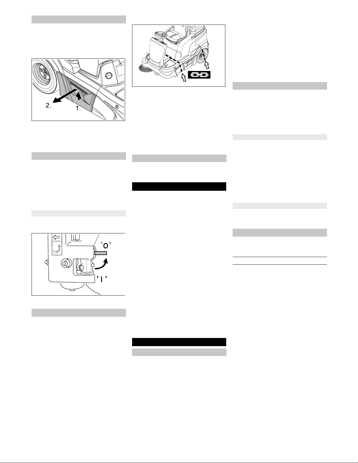
Replace the front wheel
1 Front wheel
2 Nut
3 Intake
Raise machine using vehicle jack.
Loosen both screws on the wheel axle
by 1-2 rotations. If necessary, hold up a
second wrench to loosen them.
Remove the wheel together with the ax-
le.
Have the defective wheel repaired by a
specialised repair shop.
Tighten the repaired front wheel with
the axle and nut to the retainer.
Lower machine using vehicle jack.
DANGER
Risk of burns on account of hot surfaces!
Allow engine to cool down.
Wait for at least 5 minutes after switch-
ing off the engine before checking the
engine oil fill level.
Open the device hood.
1
Oil drain hose
2 Oil dipstick
Unscrew and withdraw oil dipstick.
Wipe off and insert the oil dipstick (do
not turn it in).
Remove the oil dip one more time and
check the oil level.
– The oil level must lie between “MIN“
and “MAX“ marking.
– Add motor oil if the oil level is below the
"MIN" marking.
– Do not fill oil above the "MAX" marking.
Fill motor oil into the oil fill neck.
Note: For filling in the motor oil, use ac-
cessories such as a bent funnel tube or
an oil-change pump 6.491-538.
For oil type refer to Chapter "Technical
specifications".
Wait at least 5 minutes.
If the engine oil level is correct, screw in
the oil dipstick.
Danger
Risk of burns due to hot oil!
Allow engine to cool down.
Open the device hood.
Ready a catch bin for appr. 1 litre oil.
Unscrew the locking screw of the oil
drain hose and drain the oil.
Screw in the locking screw and tighten
it again.
Unscrew and withdraw oil dipstick.
Fill motor oil into the oil fill neck.
For oil type and filling quantity refer to
Chapter "Technical specifications".
Wait at least 5 minutes.
Check engine oil level.
If the engine oil level is correct, screw in
the oil dipstick.
Deliver the old oil to the respective col-
lection centres.
DANGER
Risk of burns on account of hot surfaces!
Allow engine to cool down.
1 Wing bolt
Remove the battery
Check the tyre pressure
Replacing wheel
Tightening torque (Nm) 56 Nm
Check engine oil level and top up, if
required
Change the engine oil
Change the air filter
24 EN
- 9
2 Air filter housing
3 Filter inlay
Remove the wing screw.
Remove the air filter housing.
Take out the filter inlay.
Clean the interior of the air filter reser-
voir.
Clean or replace the filter inlay.
Install a new filter inlay.
Fit the air filter casing and secure it by
means of the butterfly nut.
CAUTION
Risk of injury! Do not remove the spark plug
connector manually.
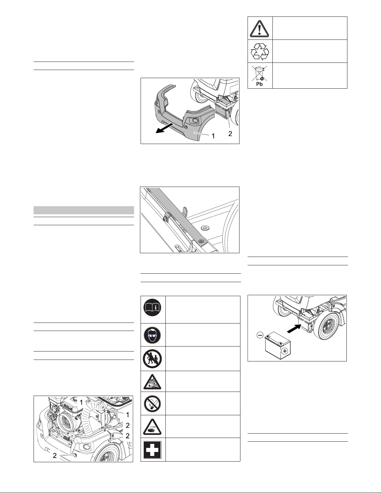
1 Vacuum line
2 Ignition plug
3 Casing
Pull the vacuum line out of the casing.
Remove the spark plug connector using
suitable tools/tongs.
Unscrew and clean spark plug.
Screw in cleaned or new spark plug.
Push on spark-plug connector.
Reinsert the vacuum pipe into the cas-
ing.
DANGER
Risk of burns on account of hot surfaces!
CAUTION
This inspection may only be carried out
when the engine is warm
Open the device hood.
1 Equalising container
2 MAX oil level
3 MIN oil level
Check oil level in the equalisation con-
tainer.
The filling level should be between the
"Max" and "Min" marking.
If hydraulic oil is missing:
Remove the lid of the equalising reser-
voir and refill hydraulic oil.
For oil type refer to Chapter "Technical
specifications".
Close the lid.
Check tyre pressure.
The side-brushes lift up.
Drive sweeper on to a smooth, even
surface covered with a visible layer of
dust or chalk.
Lower side-brushes and allow them to
briefly rotate.
The side-brushes lift up.
Drive machine backwards.
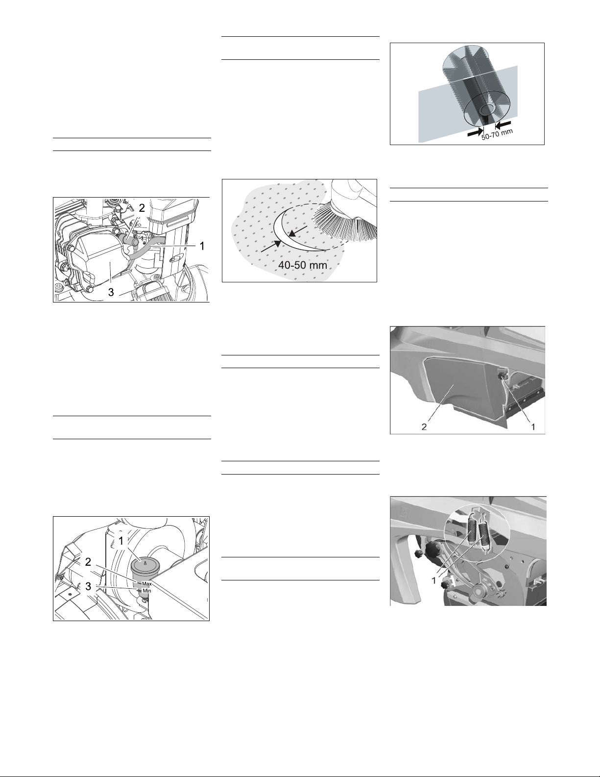
Park the sweeper on an even surface.
Check sweeping mirror.
The width of the sweeping track should
lie between 40-50 mm.
Note: The side brush floating mounting ad-
justs the sweeping track as the bristles
wear down. The side brush must be re-
placed if it becomes too worn.
Park the sweeper on an even surface.
Set programme switch to step 1 (driv-
ing). Side brushes lift up.
Turn ignition key to "0" and remove it.
Loosen 3 fastening screws on the un-
derside.
Remove the wiper blade.
Clip new side brushes on to driver and
screw on.
Park the sweeper on an even surface.
Set programme switch to step 1 (driv-
ing). Roller brush is raised.
Turn ignition key to "0" and remove it.
Secure the machine with wheel
chock(s) to prevent it from rolling away.
Remove belts or cords from roller
brush.
Note: The side brush floating mounting of
the
roller brush adjusts the sweeping track
as the bristles wear down. The roller brush
must be replaced if it becomes too worn.
Set programme switch to step 1 (driv-
ing). The side brush and roller brush are
raised.
Drive sweeper on to a smooth, even
surface covered with a visible layer of
dust or chalk.
Lower roller brush and allow it to briefly
rotate.
Raise roller brush.
Press pedal which raises bulk waste
flap and keep pressed.
Drive machine backwards.
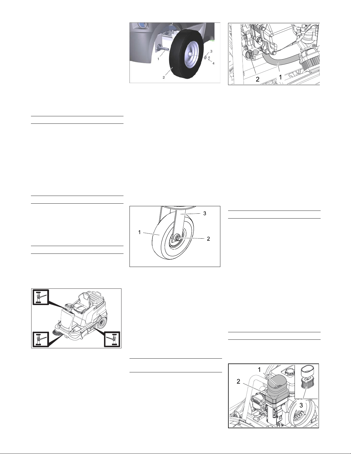
Check sweeping mirror.
The sweeping track should have an
even rectangular shape which is be-
tween 50 and 70 mm wide.
Replacement is due if a visible deteriora-
tion in sweeping performance caused by
bristle wear is evident.
Park the sweeper on an even surface.
Set programme switch to step 1 (driv-
ing). Roller brush is raised.
Turn ignition key to "0" and remove it.
Secure the machine with wheel
chock(s) to prevent it from rolling away.
Raise slightly the waste container on
the left side and pull it out.
1 Screw
2 Side panels
Loosen the fastening screw on the left
side-panel.
Remove side panel.
1 Spring
Unhook both draw springs.
Clean or replace the spark plug
Check hydraulic oil level and refill
hydraulic oil
Checking the sweeping mirror of the
side-brushes
Replacing side brush
Checking roller brush
Check the sweeping mirror of the
sweeping roller
Replacing roller brush
25EN
- 10
1 Fastening screw of the under-pressure
can
2 Fastening nut of the bulk waste flap
3 Screw of the roller brush crank
Unscrew the fastening screws of the
vacuum socket and release the lever.
Turn the fastening nut of the bulk waste
flap and unhook the bulk waste flap.
Unscrew and withdraw bolt on the roller
brush swinging arm.
1 Cover
2 Roller brush
Push the roller brush cover backwards
and remove it.
Pull out roller brush.
Push new roller brush into the roller
brush housing and onto the drive pin.
Note: When installing the new roller
brush, ensure correct positioning of the
bristle assembly.
Installation position of roller brush in direc-
tion of travel
Position roller brush cover.
Fit the fastening screws and nuts.
Hook the draw spring in.
Screw on side panel.
Push in the waste containers on both
the sides and lock them.
Park the sweeper on an even surface.
Set programme switch to step 1 (driv-
ing). Roller brush is raised.
Turn ignition key to "0" and remove it.
Secure the machine with wheel
chock(s) to prevent it from rolling away.
Raise slightly the waste containers on
both sides and pull them out.
Open the fastening screws of the side
panels on both sides.
Remove side panels.
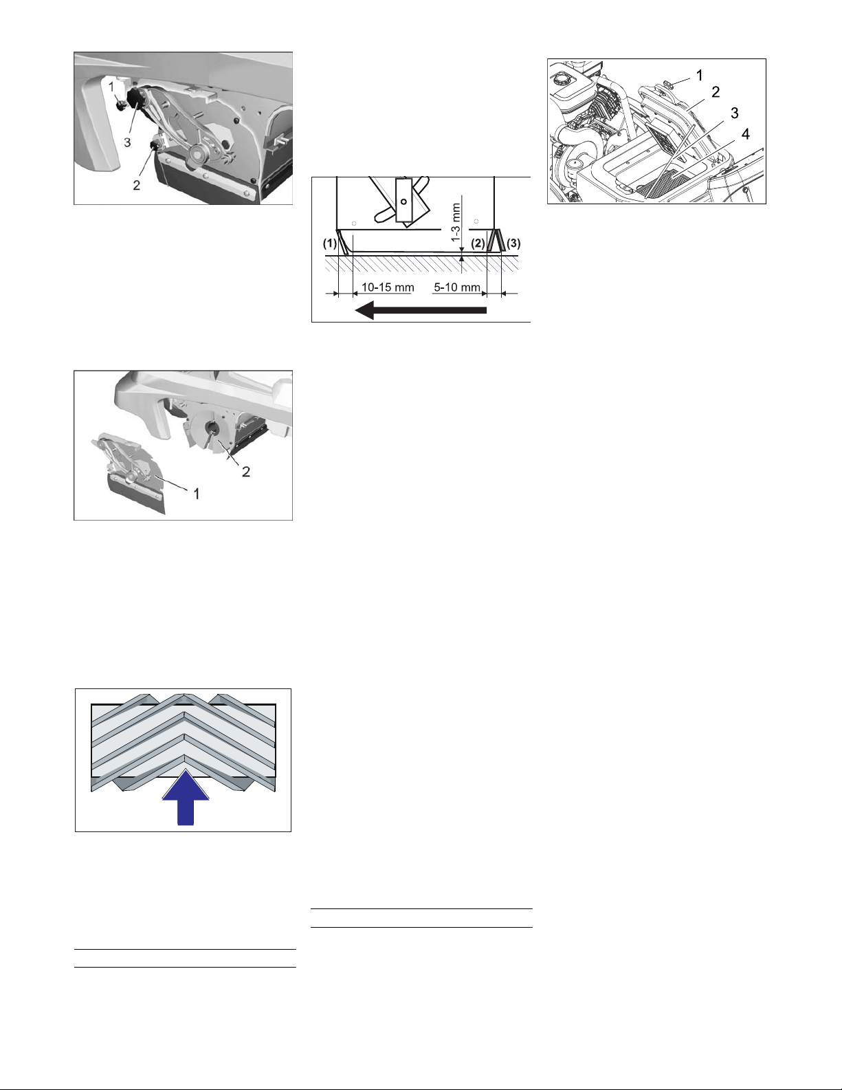
Front sealing strip
Loosen retaining nuts for the front seal-
ing strip (1) slightly (to replace, un-
screw).
Screw on new sealing strip without fully
tightening the nuts.
Adjust sealing strip.
Set the distance between the sealing
strip and the floor so that the bottom
edge trails behind at a distance of be-
tween 10-15 mm.
Tighten nuts.
Rubber strip
If worn, replace.
Unscrew retaining nuts for the rubber
strip (2).
Screw on new rubber strip.
Rear sealing strip
Set the distance between the sealing
strip and the floor so that the bottom
edge trails behind at a distance of be-
tween 5 and 10 mm.
If worn, replace.
Unscrew retaining nuts for rear sealing
strip (3).
Screw on new sealing strip.
Side sealing strips
Slightly loosen retaining nuts for the
side sealing strip (to replace, unscrew).
Screw on new sealing strip without fully
tightening the nuts.
To set the floor clearance, insert a
sheet with a thickness of between 1 and
3 mm under the sealing strip.
Adjust sealing strip.
Tighten nuts.
Screw on side panels.
Push in the waste containers on both
the sides and lock them.
WARNING
Wear a dust mask when working around
the dust filter. Observe safety regulations
on the handling of fine particles.
Note: Wait at least 1 minute before remov-
ing
the dust filter so that the dust can settle.
Open the device hood.
1 Screws (2x)
2 Lid with cleaning device
3 Support
4 Dust filter (flat-fold filter)
5 Suction blower
Loosen the screws.
Fold the lid up and secure it by means
of the support.
Take out the dust filter.
Check dust filter, clean or replace
Insert cleaned or new dust filter.
Close the lid.
Tighten the screws.
Adjusting and replacing sealing strips
Check/replace dust filter
26 EN
- 11
Check hoses at the suction blower for
leaks and tight seating from time to
time.
Turn ignition key to "0" and remove it.
Danger
The engine requires approx. 3-4 seconds
to come to a standstill once it has been
switched off. During this time, stay well
clear of the working area.
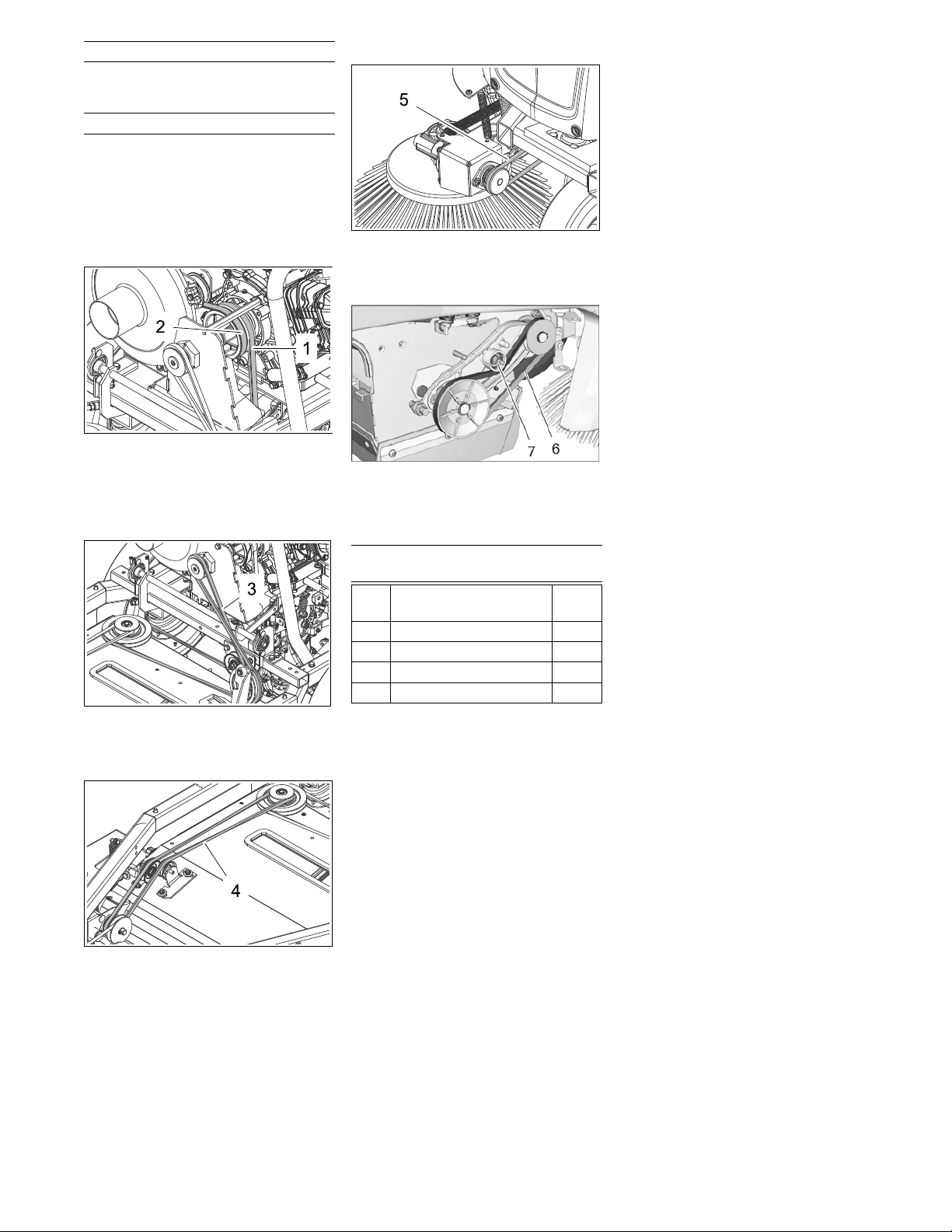
Open the device hood.
V-belt axle drive (1) and V-belt suction
blower (2)
Check the V-belt axle drive (1) and V-
belt suction blower (2) for tension, wear
and damage.
Drive belt (3)
Check drive belt (3) for tension, wear
and damage.
Drive belt (4)
Check drive belt (4) for tension, wear
and damage.
Circular belt side brush (5)
Check circular belt side brush (5) for
tension, wear and damage.
V-belt sweeping drive (6) and screw (7)
Check V-belt of the roller brush drive (6)
for tension, wear and damage.
Tighten the V-belt at the screw if neces-
sary.
The drive control/electronic system is in-
stalled behind the front panel. To replace a
fuse, the front panel must be removed.
Loosen the front panel screws.
Remove front panel.
Replace defective fuses.
Note: The assignment of fuses is indi-
cated on the inside of the panel. Only
use fuses with identical safety ratings.
Replace front panel.
Check suction blower
Checking drive belt
Replacing fuses of drive control/
electronic system
F 1 Main fuse
Battery pole fuse
125 A
F 2 Printed board 7.5 A
F 3 Charge regulator 25 A
F 4 Printed board 25 A
F 5 Beacon light (optional) 7.5 A
27EN

- 12
Troubleshooting
Fault Remedy
Appliance cannot be started Sit on the driver seat, the seat contact switch gets activated.
Check, if the stop switch on the combustion engine is in the "ON" position.
Refuel
Open fuel cock
Check fuel pipes, connections and joints and maintain them if required
Charging battery
Check and clean spark plug, replace if necessary.
Inform Kärcher Customer Service.
Engine is running erratically Clean or replace air filter
Check fuel pipes, connections and joints and maintain them if required
Inform Kärcher Customer Service.
Engine is running but machine is
not moving
Check setting of freewheel lever
Inform Kärcher Customer Service.
Engine is running but machine is
only moving slowly
Allow machine to warm up for approx. 3 minutes in sub-zero temperatures
Inform Kärcher Customer Service.
Machine is not sweeping properly Check roller brush and side brushes for wear, replace if necessary.
Check function of bulk waste flap
Check sealing strips for wear, adjust or replace as required
Check belts of sweeping drive.
Inform Kärcher Customer Service.
Dust gathers in the machine
Insufficient vacuum performance
Empty waste container
Check hoses of suction blower for absence of leakness.
Clean and check the dust filter, replace if necessary.
Check the dust filter for proper seating.
Close wet/dry flap
Check sealing strips for wear, adjust or replace as required
Inform Kärcher Customer Service.
Side brush or roller brush is not be-
ing lowered; under-pressure sys-
tem is defective
Inform Kärcher Customer Service.
Roller brush does not turn. Set programme switch to stage 2 or 3.
Remove belts or cords from roller brush
Check V-belt tension
Inform Kärcher Customer Service.
A short blow-off sound can be
heard.
The appliance is OK, the automatic filter cleaning system is working
The motor cannot be switched off
(Key position on "0")
Open the appliance cover and close the petrol cock. Risk of injury on account of rotating belts!
Close the cover and wait until the motor turns off.
28 EN

- 13
Technical specifications
KM 90/60 R G Adv
Machine data
Length x width x height mm 1695 x 1060 x 1260
Net weight (transport weight) kg 265
Permissible overall weight kg 440
Driving speed km/h 8
Cleaning speed km/h 4
Climbing capability (max.) % 18
Roller brush diameter mm 250
Roller brush width mm 615
Side brush diameter mm 410
Surface cleaning performance without side brushes m
2
/h 4920
Surface cleaning performance with 1 side brushes m
2
/h 7200
Surface cleaning performance with 2 side brushes m
2
/h 9480
Working width without side brushes mm 615
Working width with 1 side brushes mm 900
Working width with 2 side brushes mm 1185
Volume of waste container l 60
Protection type, drip-proof -- IPX 3
Engine
Type -- Subaru EX27
1 cyl., four-stroke
Cylinder capacity cm
3
265
Power kW/PS 5,3 / 7,2 (2.800 min
-1
)
Fuel type -- Petrol, unleaded
Fuel tank capacity l 5.6
Spark plug, NGK -- BR-4HS
Maintenance-free batteries V, Ah 12, 40
Oil grades
Engine oil - type -- SAE 15 W 40
Filling quantity l 1.0
Drive axle of the hydraulic part -- SAE 20 W 50
Tyres
Size, front -- 3.00-4 4PR
Air pressure, front bar 4.0
Size, rear -- 4.00-8 6PR
Air pressure, rear bar 4.0
Brake
Service brake -- hydrostatic
Parking brake -- automatic (with spring)
Filter and vacuum system
Filter system TACT
Category of use – filter for non-hazardous dust -- M
Working conditions
Temperature °C 0...+ 40
Air humidity, non-condensing % 0 - 90
Values determined as per EN 60335-2-72
Noise emission
Sound pressure level L
pA
dB(A) 78
Uncertainty K
pA
dB(A) 3
Sound power level L
WA
+ Uncertainty K
WA
dB(A) 97
Machine vibrations
Hand-arm vibration value m/s
2
< 2.5
Seat m/s
2
0.7
Uncertainty K m/s
2
0.2
29EN
- 14
We hereby declare that the machine de-
scribed below complies with the relevant
basic safety and health requirements of the
EU Directives, both in its basic design and
construction as well as in the version put
into circulation by us. This declaration shall
cease to be valid if the machine is modified
without our prior approval.
The undersigned act on behalf and under
the power of attorney of the company man-
agement.
Authorised Documentation Representative
S. Reiser
Alfred Kärcher GmbH Co. KG
Alfred-Kärcher-Str. 28 - 40
71364 Winnenden (Germany)
Phone: +49 7195 14-0
Fax: +49 7195 14-2212
Winnenden, 2012-04-01
EU Declaration of Conformity
Product: Vacuum sweeper
Type: 1.047-xxx
Relevant EU Directives
2006/42/EC (+2009/127/EC)
2014/30/EU
2000/14/EC
Applied harmonized standards
EN 50082-1:1997
EN 60335–1
EN 60335–2–72
Applied national standards
CISPR 12
Applied conformity evaluation method
2000/14/EC: Appendix V
Sound power level dB(A)
Measured: 94
Guaranteed: 97
CEO
Head ofApprobation
Accessories
Side brushes, stand-
ard
6.906-132.0
For cleaning of indoor and outdoor areas.
Hard side-brushes 6.905-625.0
For removing stubborn dirt in the external
area; resistant to moisture.
Side-brushes, soft 6.905-626.0
Especially for sweeping fine dust on even
floors.
Roller brush, standard 4.762-430.0
Resistant of wear and moisture. Universal
bristles for inside and outside cleaning.
Roller-brush, soft 4.762-442.0
With natural bristles especially for fine
dust sweeping on smooth indoor floors.
Not resistant to wetness; not for abrasive
surfaces.
Roller-brush, hard 4.762-443.0
For removing stubborn dirt in the external
area; resistant to moisture.
Flat-fold filter (dust fil-
ter)
6.907-352.0
Roller brush, antistat-
ic
4.762-441.0
Upgrade kit solid rub-
ber tyres
2.641-129.0
Upgrade kit side
brush left
2.642-693.0
Attachment set: over-
all lamp
2.642-989.0
Upgrade kit double
TACT
2.643-176.0
Set holder brush
homebase
4.035-523.0
Set coarse dirt pliers
homebase
4.035-524.0
30 EN