
Shenzhen Xtooltech Intelligent Co., LTD
X100PAD3
Automotive
Diagnostic Tool
User Manual

I
Please read this user manual carefully before using the X100PAD3
Auto Key Programmer. When reading the manual, please pay
attention to the words “Note” or “Caution” and read them carefully
for appropriate operation.
TRADEMARKS
is a registered trademark of Shenzhen Xtooltech
Intelligent CO., LTD.
In countries that the trademarks, service marks, domain names,
logos and the name of the company are not registered, Xtool claims
that it still reserves the ownership of the unregistered trademarks,
service marks, domain names, logos and the company name. All
other marks for the other products and the company’s name
mentioned in the manual still belong to the original registered
company.
You may not use the trademarks, service marks, domain names,
logo and company name of Xtool or other companies mentioned
without written permission from the trademark holder.
Xtool reserves the right for the final interpretation of this manual
content.

II
COPYRIGHT
Without the written consent of Shenzhen Xtooltech Intelligent Co.,
Ltd., any company or individual shall not copy or backup this
operation manual in any form (electronic, mechanical, photocopying,
recording or other forms).
DECLARATION
This manual is designed for the usage of X100PAD3 Auto Key
Programmer, and provides operating instructions and product
descriptions for users of the X100PAD3 Auto Key Programmer.
No part of this manual can be reproduced, stored in a retrieval
system or transmitted, in any form or by any means (electronic,
mechanical, photocopying, recording, or otherwise), without the
prior written permission of Xtool.
Use the device only as described in this manual. Xtool is not
responsible for any consequences of violating the laws and
regulations caused by using the product or its data information.
Xtool shall not be liable for any incidental or consequential damages
or for any economic consequential damages arising from the

III
accidents of individual users and the third parties, misuse or abuse
of the device, unauthorized change or repair of the device, or the
failure made by the user not to use the product according to the
manual.
All information, specifications and illustrations in this manual are
based on the latest configurations and functions available at the
time of printing. Xtool reserves the right to make changes at any
time without notice.
OPERATION INSTRUCTIONS
For safe operation, please follow the instructions below:
⚫ Keep the device away from heat or fumes when you are using it.
⚫ If the vehicle battery contains acid, please keep your hands and
skin or fire sources away from the battery during testing.
⚫ Exhaust gas of vehicle contains harmful chemicals, please
ensure adequate ventilation.
⚫ Do not touch the cooling system components or exhaust
manifolds when engine is running due to the high temperatures
reached.
⚫ Make sure the car is securely parked, Neutral is selected or the
selector is at P or N position to prevent the vehicle from moving
when engine starts.

IV
⚫ Make sure the (DLC) diagnostic link connector is functioning
properly before starting the test to avoid damage to the
Diagnostic Tablet.
⚫ Do not switch off the power or unplug the connectors during
testing, otherwise you may damage the ECU and/or the
Diagnostic Tablet.
CAUTIONS!
⚫ Avoid shaking or dismantling the unit as it may damage the
internal components.
⚫ Do not use hard or sharp objects to touch the LCD screen;
⚫ Do not use excessive force;
⚫ Do not expose the screen to strong sunlight for a long period.
⚫ Please keep it away from water, moisture, high temperature or
very low temperature.
⚫ If necessary, calibrate the screen before testing to ensure the
accuracy of LCD performance.
⚫ Keep the main unit away from strong magnetic fields.

V
AFTERSALES-SERVICES
E-Mail: supporting@xtooltech.com
Tel: +86 755 21670995 or +86 755 86267858 (China)
Official Website: www.xtooltech.com

i
CONTENT
TRADEMARKS ..............................................................................I
COPYRIGHT .................................................................................II
DECLARATION ............................................................................II
OPERATION INSTRUCTIONS .................................................... III
CAUTIONS! ................................................................................ IV
AFTERSALES-SERVICES .......................................................... V
1 GENERAL INTRODUCTION ..................................................4
X100PAD3 Tablet ...................................................................................... 5
Front View of Tablet .................................................................................................................................. 5
Back View of Tablet ................................................................................................................................... 6
Host Ports ..................................................................................................................................................... 7
KC100 Key Programmer .......................................................................... 8
EEPROM Adapter ..................................................................................... 9
How To Connect ..................................................................................... 10
Connect To Vehicle .................................................................................................................................. 10
Connect To KC100 ................................................................................................................................... 11
Connect To EEPROM Adapter ............................................................................................................. 12
Technical Specifications ....................................................................... 13
2 GETTING STARTED ............................................................ 14
Activation Guide ..................................................................................... 14
Main Interface ......................................................................................... 19
Operation System ..................................................................................................................................... 19

ii
X100PAD3 App Menu ............................................................................................................................. 22
Function Buttons ....................................................................................................................................... 23
Navigation Buttons .................................................................................................................................. 24
Notification Bar ......................................................................................................................................... 24
3 UPDATE............................................................................... 26
4 KEY PROGRAMMING ......................................................... 27
Immobilizer Menu ................................................................................... 27
Immobilizer Functions ........................................................................... 28
Read PIN code/Pin Code Calculation ................................................................................................ 29
Check Number of Keys ........................................................................................................................... 31
Add Keys...................................................................................................................................................... 32
All Key Lost ................................................................................................................................................. 35
5 DIAGNOSIS ......................................................................... 38
Vehicle Selection .................................................................................... 38
Diagnose Functions ............................................................................... 40
6 SPECIAL FUNCTIONS ........................................................ 50
Oil Light Reset ........................................................................................ 51
EPB .......................................................................................................... 52
SAS .......................................................................................................... 53
DPF .......................................................................................................... 53
BMS Reset .............................................................................................. 54
Throttle .................................................................................................... 55
TPMS Reset ............................................................................................ 56
ABS Bleeding ......................................................................................... 56
Injector Coding ....................................................................................... 57

iii
Gearbox Match ....................................................................................... 58
Suspension ............................................................................................. 58
Windows Initialization ............................................................................ 59
Seat Calibration ...................................................................................... 59
Headlight ................................................................................................. 59
A/F Reset ................................................................................................. 60
Stop/Start Reset ..................................................................................... 60
Airbag Reset ........................................................................................... 60
Instrument Cluster ................................................................................. 60
7 REPORT .............................................................................. 61
Report ...................................................................................................... 62
DATA PLAYBACK .................................................................................. 64
File Manager ........................................................................................... 65
8 SETTINGS ........................................................................... 66
Language ................................................................................................ 66
Units ........................................................................................................ 68
My Workshop Info .................................................................................. 68
Firmware Information ............................................................................. 69
About ....................................................................................................... 71
9 REMOTE ASSISTANCE ...................................................... 72
10 TROUBLESHOOTING ......................................................... 74

4
1 GENERAL INTRODUCTION
The X100PAD3 Auto Key Programmer is a professional key
programming device, based on the Android operating system. It
supports multi-language switching and is suitable for different
countries and regions. With KC100*, this auto key programmer
supports key programming functions like read PIN code/read
immobilizer data/add key/all key lost for various vehicles, and
supports basic diagnosis functions and multiple special functions.
X100PAD3 SE doesn’t come up with KC100 key programmer.

5
X100PAD3 TABLET
The main unit of the X100PAD3 is the tablet. It allows you to operate
all the key programming and diagnosis functions, and it can also
work as a normal Android tablet.
FRONT VIEW OF TABLET
Fig 1-1 Tablet Front View
The front of the tablet is mainly a touchable display screen, you can
use your fingers to operate on the screen to finish most of the key
programming process.
6
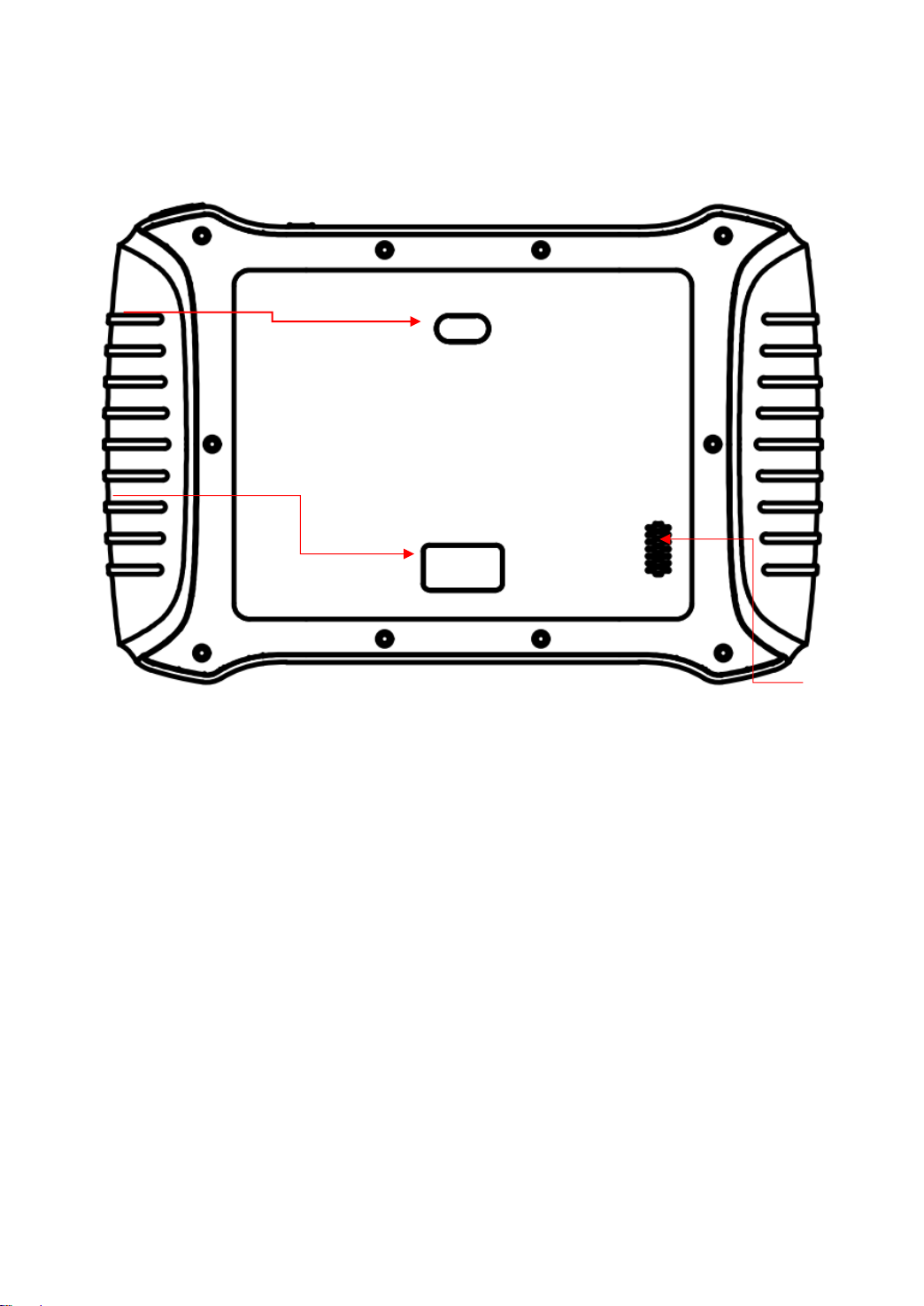
BACK VIEW OF TABLET
Fig 1-2 Tablet Back View
① Camera: Used for taking pictures.
② Nameplate: Show the basic information about tablet such as
product name and serial number, etc.
③ Loudspeaker: It supports external sound playback.
②
③
①

7
HOST PORTS
Fig 1-3 Tablet Host Ports
① USB 3.0 port: Used for data transfer for tablet & PC
communication. Accessories like KC100 & KC501 can also be
connected to this port.
② VGA port: Diagnostic communication port, which can be used
for OBD connection.
③ DC charging port: Charging port, connected to the power
adapter to charge the device.
④ Power button: Press and hold the button to turn device on/off,
short press to switch the device into sleep mode. Hold for
about 20 seconds to shut down the device forcibly.
①
②
③
④
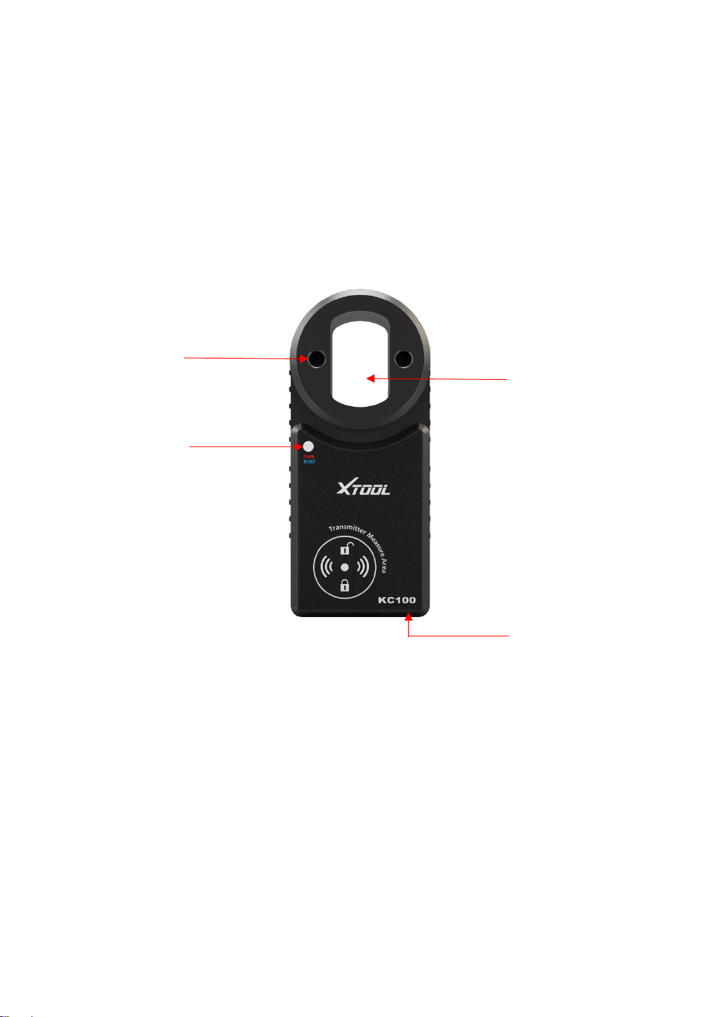
8
KC100 KEY PROGRAMMER
KC100 is a key & chip programmer that supports these functions:
⚫ Read & write car keys & key chip
⚫ Generate dealer keys
This programmer needs to work together with X100PAD3 tablet.
① Key chip slot: Insert key chip into this slot to program chips
directly.
② Key slot: Insert key into this slot to program keys.
③ Status Light: Lights up to show the status of the programmer.
Red: KC100 is now power on.
Violet: KC100 is now communicating to the device.
④ Mini USB port: Connects to the device.
④
③
②
①
9
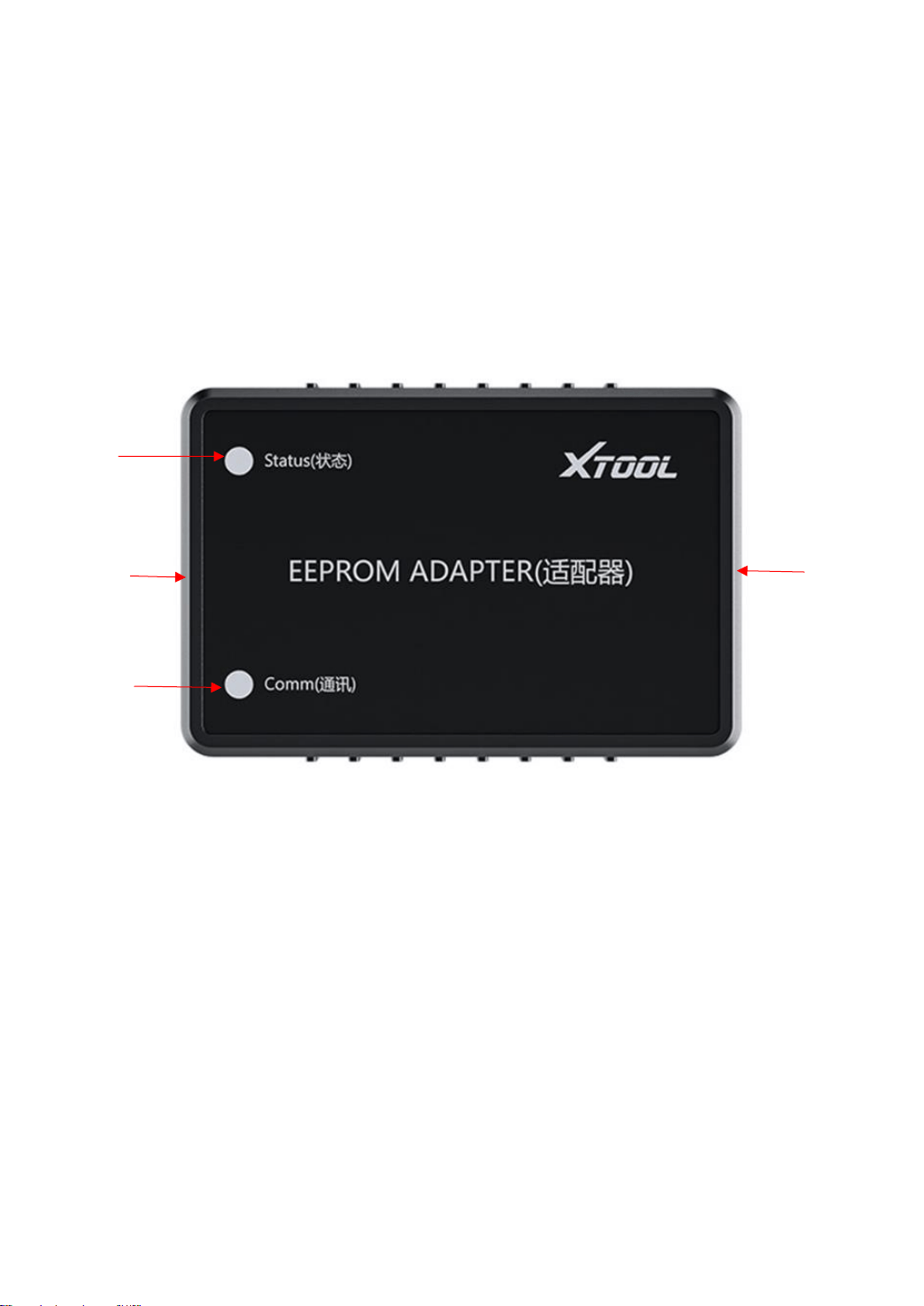
EEPROM ADAPTER
To read the EEPROM chip on the immobilizer module & dashboard,
X100PAD PLUS also comes up with an EEPROM adapter. In some
situations, you need to unweld the chip from the module to read &
write this chip.
① Status Light: Shows status of the EEPROM adapter. Will turn
red when it’s connected to any power supply.
② Comm Light: Shows communication status of the EEPROM
adapter. The light will flash when communicating to the tablet.
③ 14-Pin Port: Used to connect the EEPROM board onto the
adapter.
④ DB15 Port: Used to connect the adapter to the tablet.
①
②
③
④

10
HOW TO CONNECT
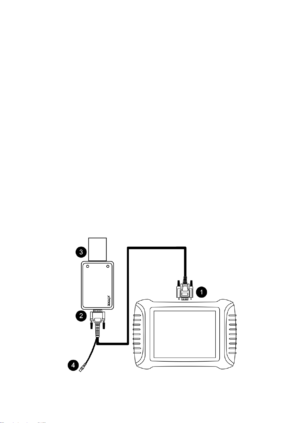
CONNECT TO VEHICLE
To start the key programming and diagnosis process, X100PAD3
needs to communicate with the vehicle itself by wire. To do that,
please follow the steps below.
1. Turn on the tablet.
2. Find the main cable and the OBD2-16 connector and connect
them with the DB15 socket.
3. Connect the vehicle and the tablet following the diagram
below. Usually, the OBD port is located under the dashboard,
inside driver’s footwell.
4. Click into the menus to perform the functions.
Some older vehicles are not using the OBD2-16 port, please make sure you’re
using the correct connector. There are 4 extra connectors that’s attached into
X100PAD3, but please contact your dealer if you need other connectors.

11
CONNECT TO KC100
In order to connect to KC100, please follow the steps below.
1. Turn on the tablet.
2. Find the cable that connects Mini USB and USB 3.0 & USB-
C.
3. Connect the Mini USB socket into the bottom of KC100 and
connect the USB 3.0 socket into the X100PAD3.
4. When the light turns on, you can perform the functions.
12
CONNECT TO EEPROM ADAPTER
To read EEPROM chips using the EEPROM Adapter, please follow
the steps below.
1. Unweld the EEPROM chip from the module.
2. Install (or weld) it onto the EEPROM board according to the
chip type.
There are 3 rows on the board and each row represents a type of EEPROM
chip, so please recognize the chip you are using first and install it onto the
right side of the board.
3. Connect the board to the 14pin port of the EEPROM Adapter.
4. Connect the other side of the adapter to the main cable and
connect the cable to the device.
If the OBD2 connector is installed on the main cable, you need to take it
out first in order to connect to the EEPROM Adapter.

13
TECHNICAL SPECIFICATIONS
Table 1-1 Specifications
Item
Description
OS
Android 5.1
Processor
Quad-core processor 1.8GHz
Ram
2G
Rom
64G
Display
8-inch capacitive, 1024×768 resolution
Connectivity
⚫ USB
⚫ Wi-Fi
⚫ Bluetooth
Camera
8-megapixel autofocus rear camera with
flash
Sensor
Gravity sensor
Audio Input/ Audio
Output
Microphone/ Loudspeaker
Ports
⚫ USB3.0
⚫ DC charging port
⚫ VGA port
Battery
10000mAh 3.7V lithium polymer battery
Input Voltage
12V DC
Operating
Temperature
-10~40℃
Relative Humidity
< 90%
Dimensions
275*183*34mm

14
2 GETTING STARTED
ACTIVATION GUIDE
When you turn on the system for the first time, the system will
automatically enter the guide process and request the user to select
the system operating language.
Fig 2-1
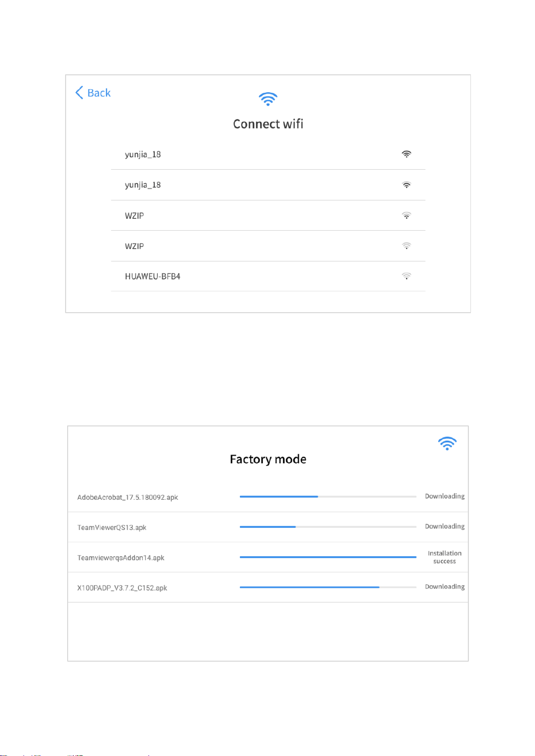
After selecting the system language, click Next to enter the Wi-Fi
connection page, as shown below:
15
Fig 2-2
Select a network to connect to on the Wi-Fi connection page.
After successful network connection, the automatic system will jump
to Factory mode to download the software:
Fig 2-3

16
Once the software has been downloaded, the tablet will
automatically reboot and request the system language selection
again.
Fig 2-4
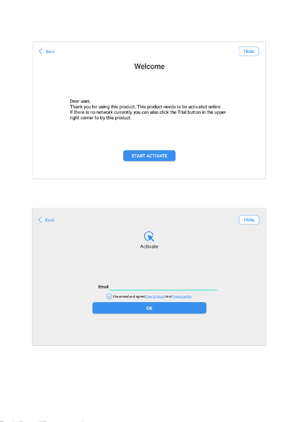
After setting the system language, you will enter the activation page,
as shown in the figure below. You can also click the "Trial" button in
the upper right corner to try it out before activation.
17
Fig 2-5
Click Start Activate to enter the activation page, as shown below:
Fig 2-6
18
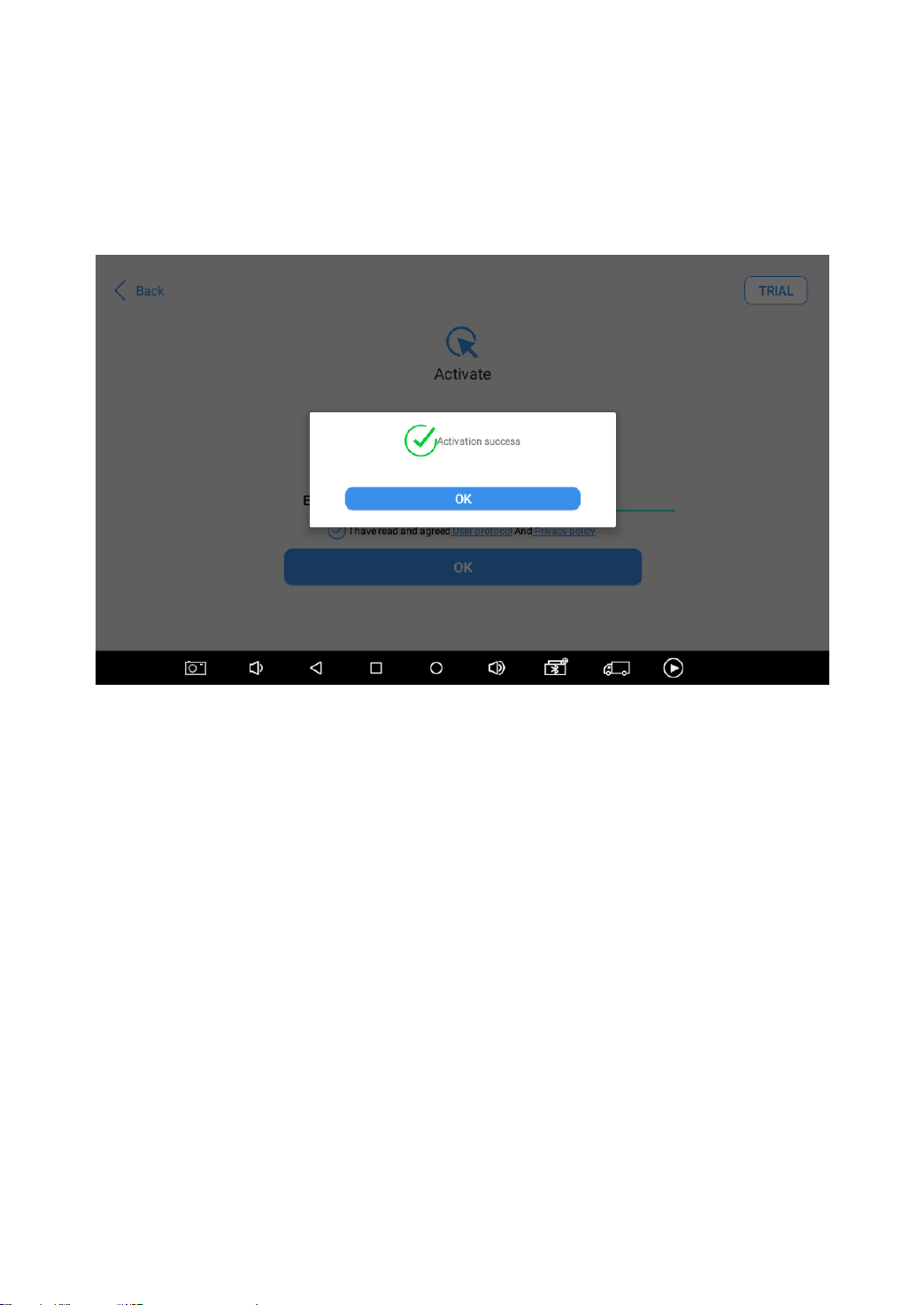
A pop-up window showing Activation Success indicates that you
have completed the first boot setup, click OK to enter the diagnostic
system and start using the device.
Fig 2-7
If you meet problems like “Registration failed”, please check your network or
contact Xtool aftersales services.
19
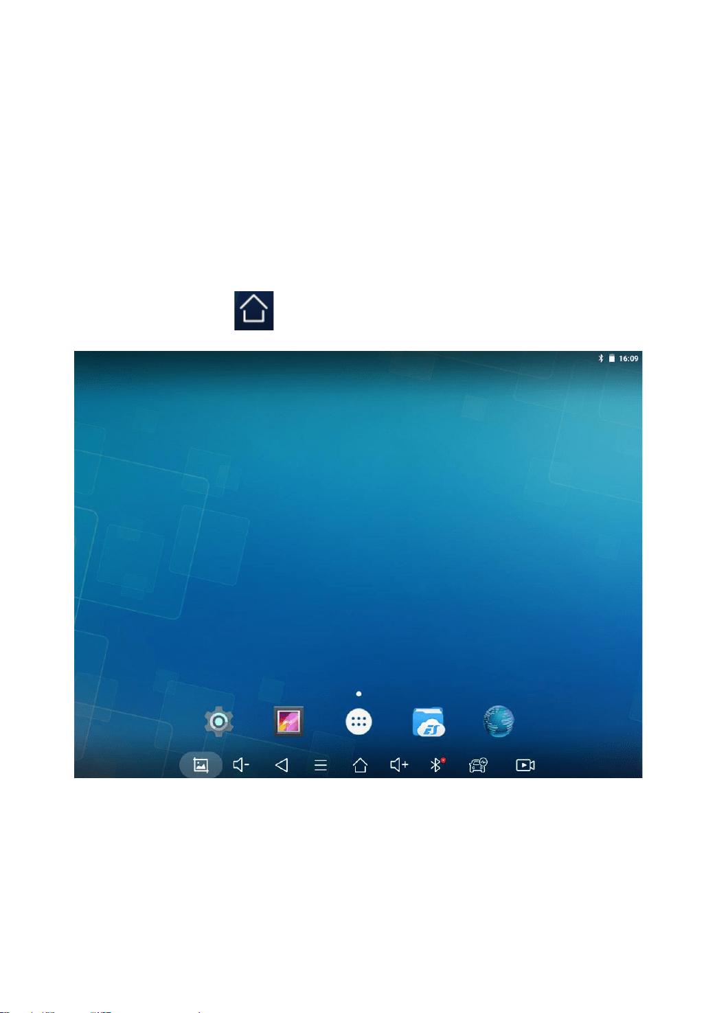
MAIN INTERFACE
OPERATION SYSTEM
The picture below (Fig 2-8) is the home screen of the operating
system of the device. You can also return to this interface at any
time by clicking 【 】on the bottom navigation bar.
Fig 2-8
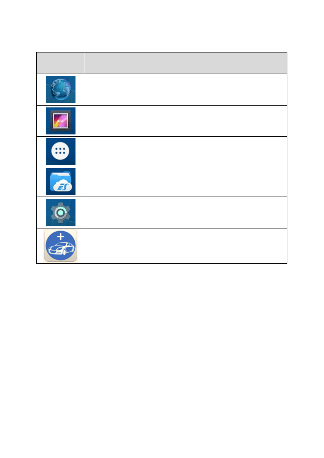
The app icons are as follows:
20
Table 2-1
Items
Descriptions
Browser
Gallery
Application Menu
ES File Explorer
Android Settings
X100PAD3 Key Programming System
a) Browser: Click on the browser icon to enter the browser to view
the official website of Xtool or search for other information.
b) Gallery: Click the Gallery icon to enter the album and you can
quickly view the pictures or screenshots stored in the device.
You can select the picture you need, click the share button on
the upper right, and send the picture to your mobile phone or PC
via Bluetooth or USB connection
c) Application Menu: Show all the apps that you have installed
into the device. Also allows you to manage them.
21
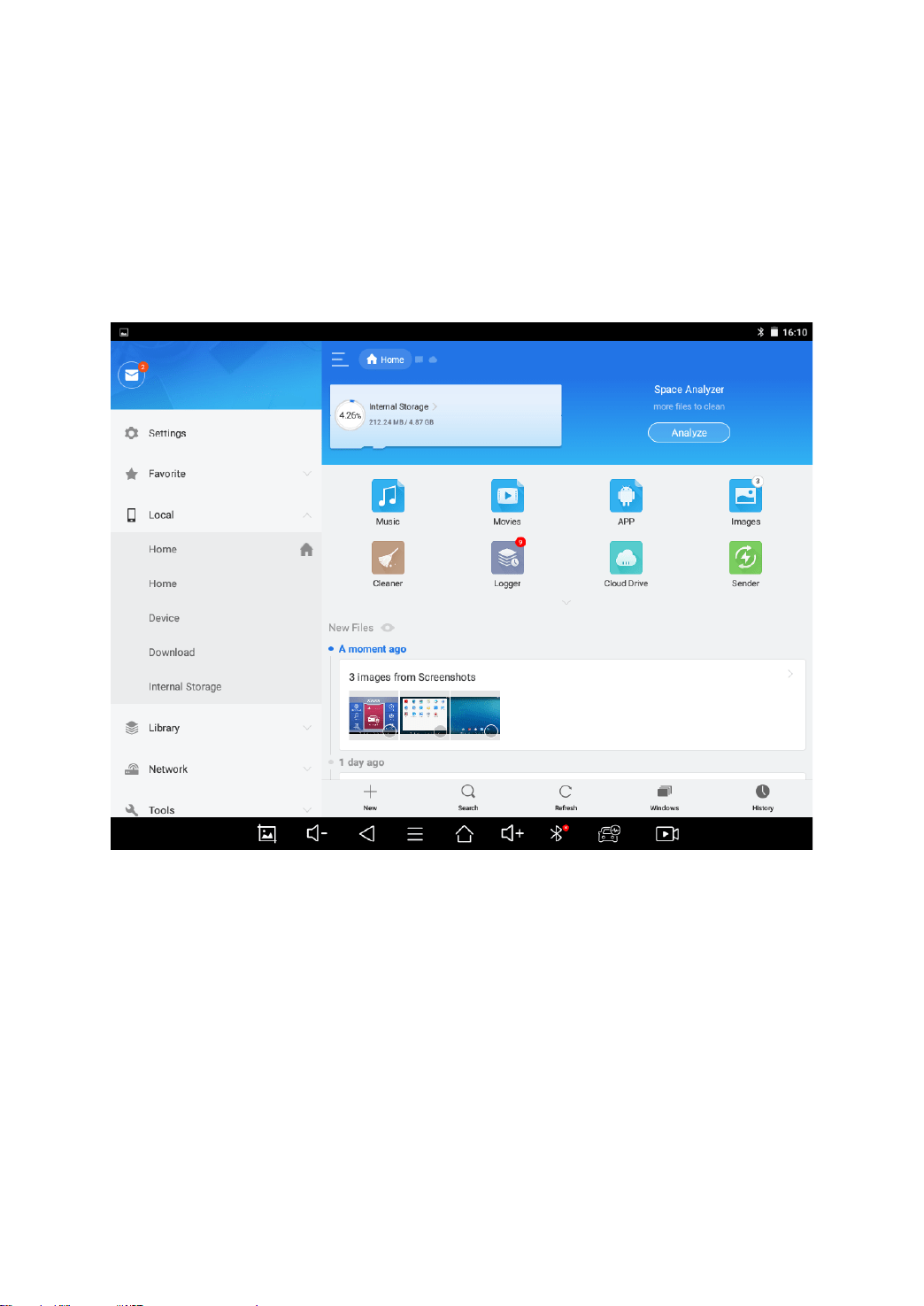
d) ES File Explorer: You can manage APP, music, files, pictures,
etc. in the device in this function, and you can also use
Local/Home/Cleaner to clean up files.
If you need to check the files inside X100PAD3 app (not recommended),
please use the file explorer inside X100PAD3 app.
Fig 2-9
e) Android Settings: Allows you to check and change the settings
of the Android system, including network, battery status,
language, device info and factory reset.
f) X100PAD3 Key Programming System: This app provides all
the key programming and diagnostic functions, and also offers
a range of special maintenance services.
It will be referred as “X100PAD3 app” later in this manual.
22
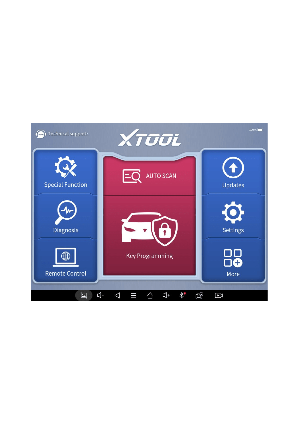
X100PAD3 APP MENU
Every time you start the tablet, you will automatically enter the
X100PAD3 app with the following main screen. Tap on diagnosis
application button on the menu, the main menu will be shown as
below:
Fig 2-10
This main menu contains Function Buttons and Navigation
Buttons. The touch screen navigation is made up by several menus,
and you can quickly access functions by clicking on the icons. A
detailed description of the menu structure can be found in the next
section Function Buttons.
23
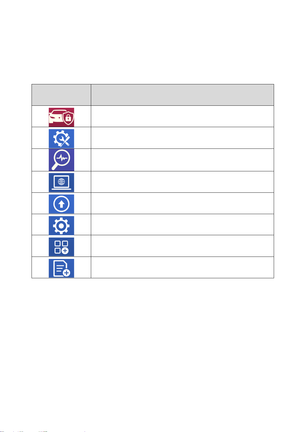
FUNCTION BUTTONS
The following table briefly describes each function button.
Table 2-2
Icon
Description
Enter immobilizer menu
Includes various special functions for vehicles
Enter vehicle diagnosis menu
Enter TeamViewer for remote support
Update the immobilizer/diagnosis software through
Internet
Select the language and unit shown in the app, and check
the Bluetooth status, device info and workshop info
View extended functions like checking reports and check
Xtool official website
Check the diagnosis report that recorded in your device,
print as PDF files, or share to other devices
24
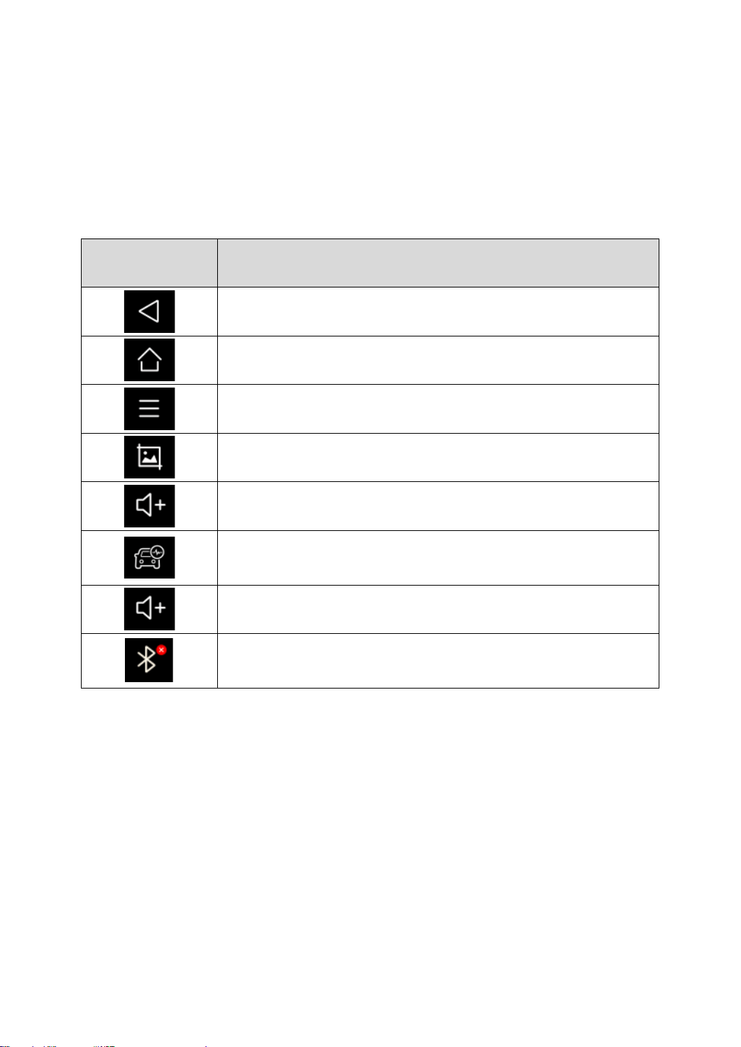
NAVIGATION BUTTONS
Instructions for operating the navigation bar buttons at the bottom
of the screen, as described in the table below:
Table 2-3
Items
Descriptions
Back to previous screen
Back to the main screen of Android system
Shows recently used applications
Press to screenshot
Increase volume
Click here to return to diagnostic vehicle models
interface
Decrease volume
Check Bluetooth status (Red – disconnected/Green
– connected)
You can find screenshots or screen-recording videos inside file explorer. The
screenshots are saved in Screenshots folder and videos in ScreenRecording
folder.
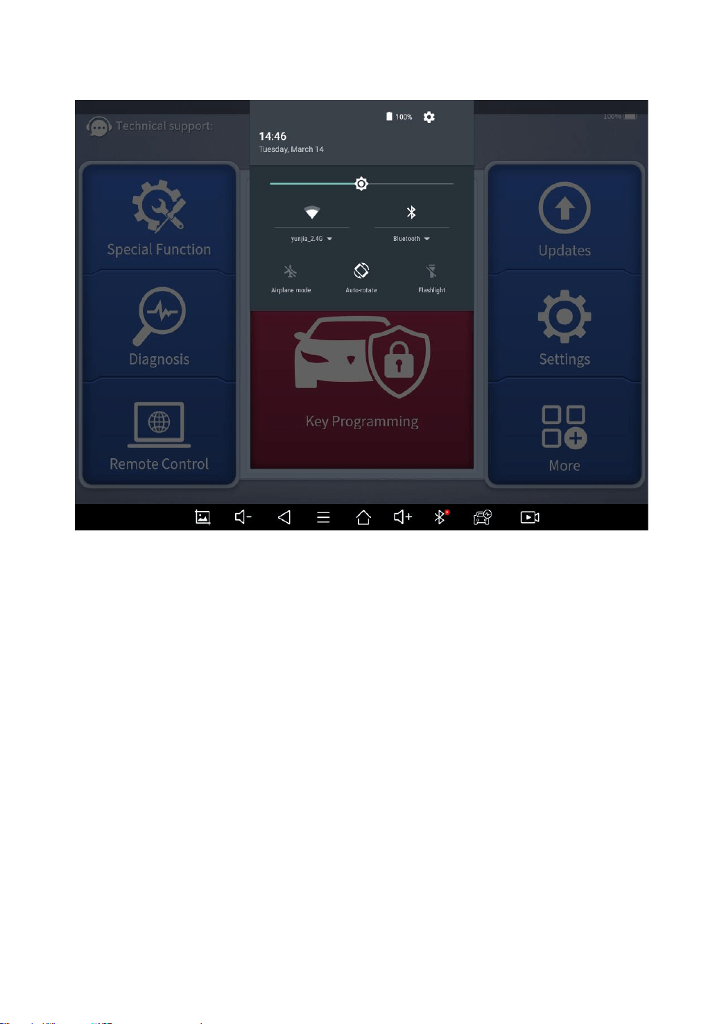
NOTIFICATION BAR
Slide down to open the notification bar. You can adjust the
brightness of the screen when you need, and you can also connect
Wi-Fi and so on.
25
Fig 2-11
26
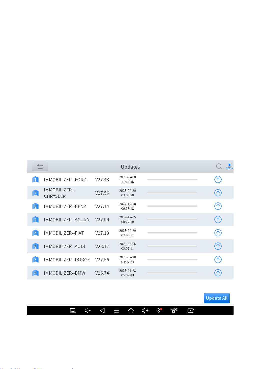
3 UPDATE
After activating the device, please update the software in "Update"
first. The device will pull all currently supported software packages
from our servers, and you can download them as needed. To
access the update application, open the diagnosis application and
click UPGRADE, and it will show as below:
X100PAD3 has a two-year free subscription when activated. When you click
“update” and it shows “your device is now out of subscription”, please contact your
dealer.
Fig 3-1

27
4 KEY PROGRAMMING
The key programming software inside X100PAD3 app can get
access to the immobilizer system inside the vehicles and supports
multiple functions like key programming, generate dealer key, all
key lost, immobilizer reset or changing, EEPROM chip coding and
much more.
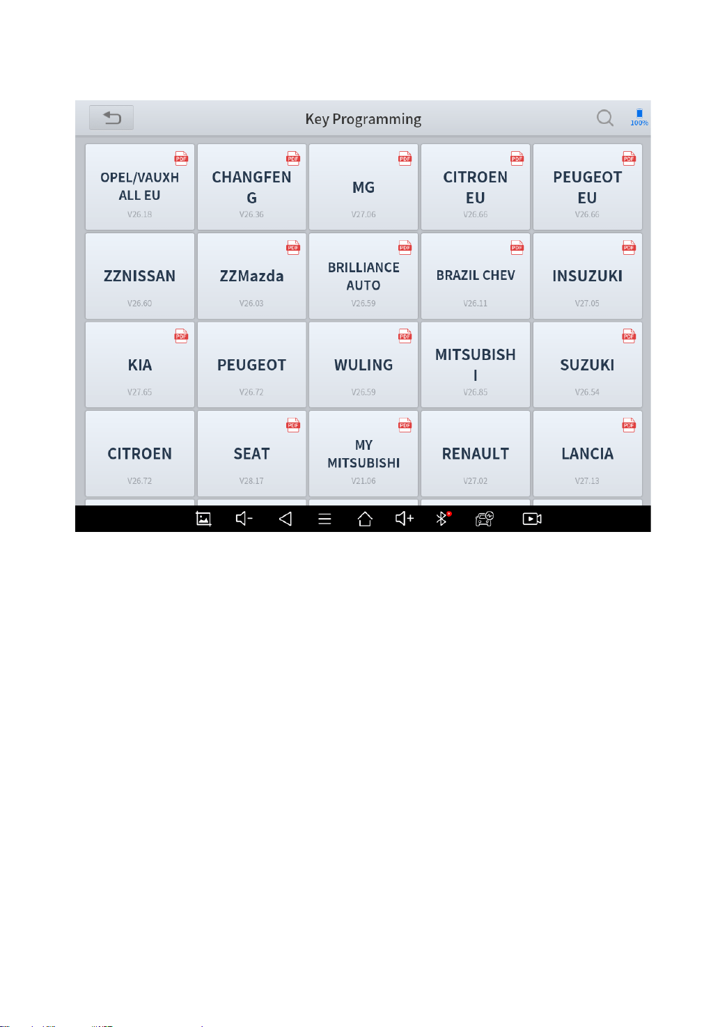
IMMOBILIZER MENU
Click “Key Programming” icon on the main screen and get into the
immobilizer menu. Choose the brand of the vehicle to start the
programming process. You can also click the search icon on the
top-right corner of the screen and find the brand you need.
For different models with different immobilizer modules, the key programming
process will be completely different. Most of the process could be done by following
the instructions on the screen. But if you are not sure how to do that, please check
the tutorials.
If you need to check if your car is supported, you can click the PDF icon at the top
right of the model brand button, or go to “XCloud” menu and go to our official website
(http://www.xtooltech.com/EN/index.html), then check Support – Function Lists and
check for details.
You may need extra accessories when working on some of the functions. Please
check XTOOL official website or your distributor for more details.
28
IMMOBILIZER FUNCTIONS
Normally the key programming software supports these functions:
⚫ Check number of keys
⚫ Read PIN code/pin code calculation
⚫ Add key
⚫ Generate dealer key
⚫ All key lost
And more…
Fig 4-3 Immobilizer Menu

29
Some examples will be provided in this manual to help you
understand the process.
For different models with different immobilizer modules, the key programming
process will be completely different. Because of that we can only give some
examples about how to do that. Most of the process could be done by following the
instructions on the screen. But if you are not sure how to do that, please check the
tutorials.
READ PIN CODE/PIN CODE CALCULATION
Let’s take Nissan/Infiniti software for example. Click “Key
Programming – Nissan/Infiniti – Pin Calculator” to enter the
system. After selecting the manufacturer (here we choose
“General”), the menu below will show up.
Fig 4-4

30
Please choose the type of your vehicle. If you have any questions,
please click “Help” for more details.
Fig 4-5
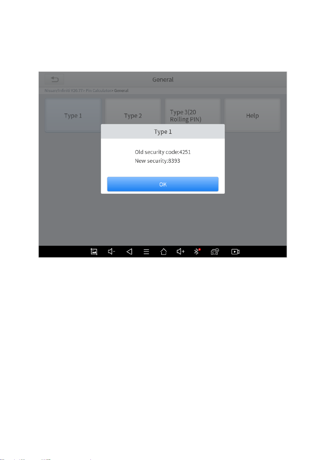
Here we choose “Type 1”, then insert the 5-digit BCM code.
The BCM for Nissan vehicles may be found under the steering wheel, behind the
glove box, behind the passenger/driver side kick panel and behind dash cluster -
depending on the model of vehicle.
31
Fig 4-6
After you inserted the code, the results will show up.
Fig 4-7
Quick Tip: If you have trouble working on Nissans, please change the language
into English, check the updates and see if there is a “NISSAN PIN DATA”. Usually
download it will solve the problem.
CHECK NUMBER OF KEYS
Here we take a 2007 Ford Focus with mechanical key as an
example. Click “Key Programming – Ford – North American Ford –
Focus – 2005-2007” to enter the system.
The process below works on most old Fords (around 2000s). If you are working
on other Ford models with similar model years, you can also check this process.

32
Fig 4-8
Click “Number of keys” and it will show the number of the keys that
are registered to the vehicle.
We suggest to check registered key amounts every time before and after you
program the keys to check if the keys have been programmed.
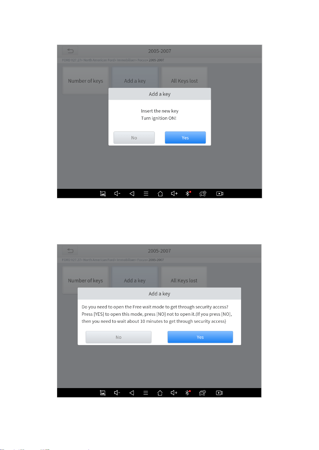
ADD KEYS
Still take the 2007 Ford Focus as an example. Click “Add key”
menu, then follow the instruction on the screen. Take a new key,
insert it into ignition, and switch ignition ON.
33
Fig 4-10
You can choose “Free-wait mode” to bypass the security access,
or you’ll need to wait for about 10 minutes. We choose “Yes” here.
34
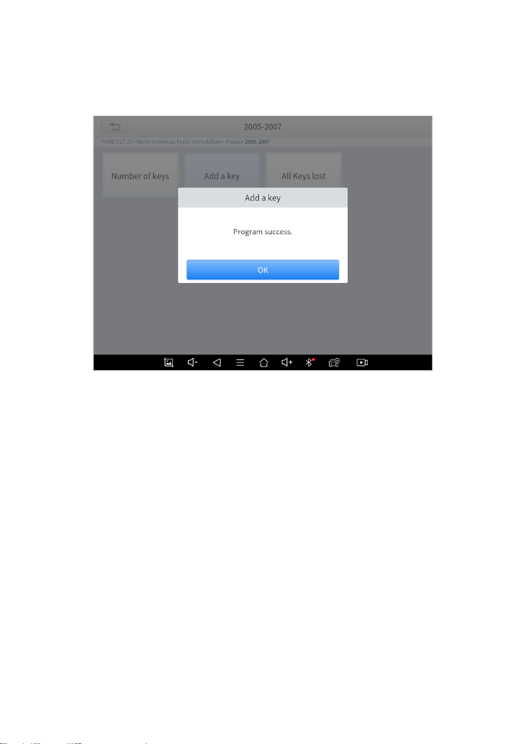
Fig 4-11
Wait for a while until it shows the results.
Fig 4-12
35
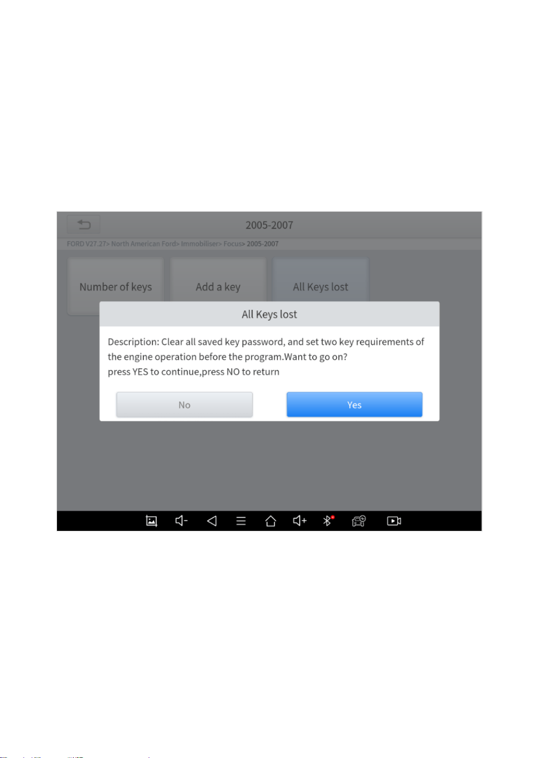
ALL KEY LOST
Still take the 2007 Ford Focus as an example. Click “All keys lost”
menu and this notice will show up. Since this is an all-key-lost
situation and we need to clear all the registered key, choose “Yes”
here.
Fig 4-13
This also has a “Free-wait mode”, click “Yes” here.
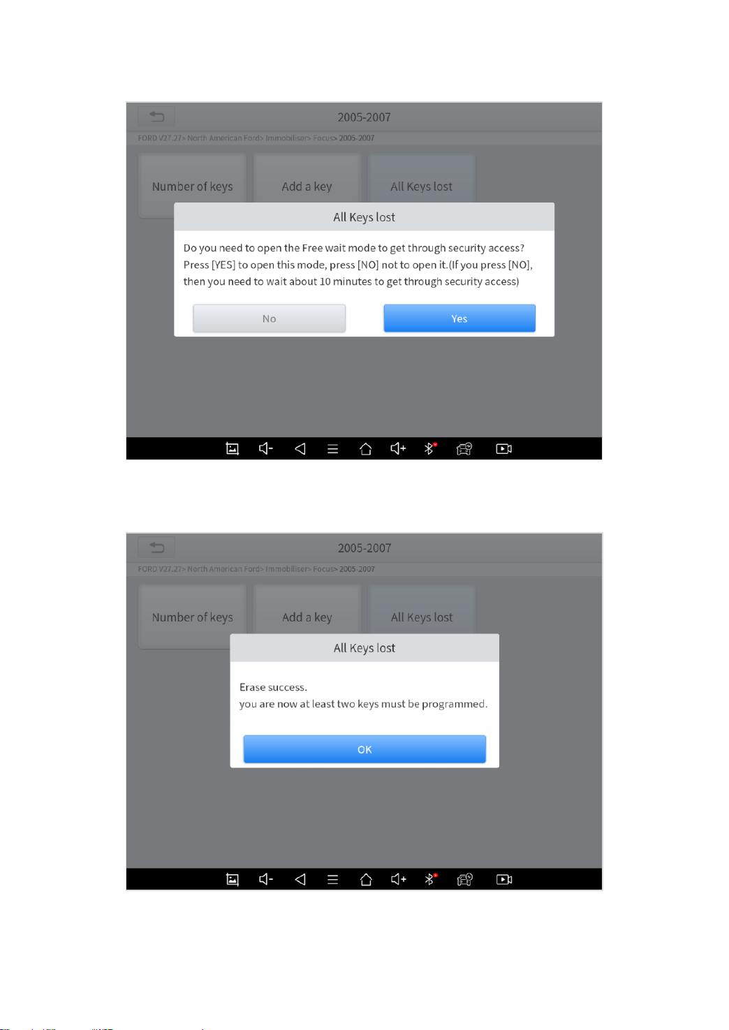
36
Fig 4-14
Wait a while until the results shows up.
Fig 4-15
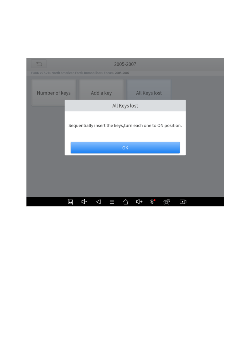
37
After successfully reset, please insert two new keys into the
ignition switch and turn them on one by one.
Fig 4-16
We suggest checking all the keys every time after you programmed the key.

38
5 DIAGNOSIS
The diagnostic application can read ECU information, read and
clear DTC and check living data and freeze frames. The diagnosis
application can access the electronic control unit (ECU) of various
vehicle control systems, including the engine, transmission, anti-
lock braking system (ABS), airbag system (SRS), and perform kinds
of actuation tests.
VEHICLE SELECTION
Click “Diagnosis” icon on the main screen and get into the diagnosis
menu. Select the region of your vehicle, click the correct brand, and
start diagnosis process.
39
Fig 5-1
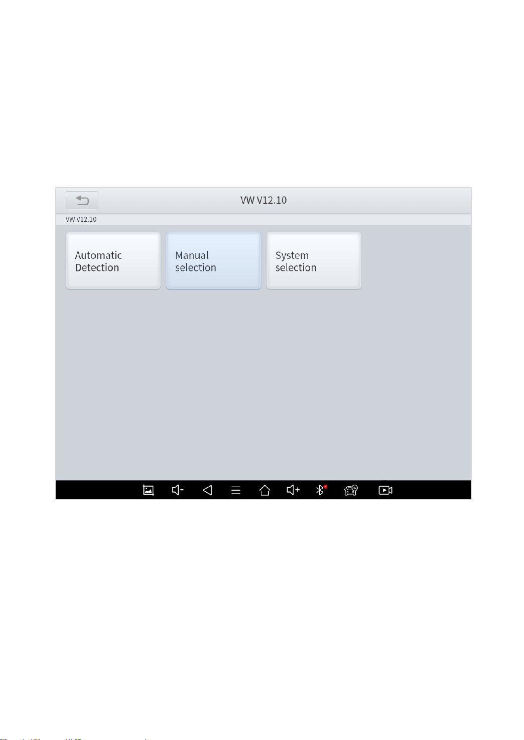
For some of the brands (like Volkswagen), when you click in the
software, there are several ways to select the model or system you
want to run a diagnosis, including Automatic Detection, Manual
Selection and System Selection.
Fig 5-2
Automatic Detection will automatically identify the vehicle's VIN
code, and then read the information of your target diagnostic object.
If you choose "Manual selection", then you can continue to select
the vehicle brand, year, and model of the vehicle in the sub-menu
to diagnosis the vehicle. Enter "System Selection", you can also
40
diagnose the vehicle according to the system according to your
needs after selecting the model.
OBDII menu supports reading the common fault codes in the engine. The DTCs
may not be the same when comparing with using common diagnosis software.
DEMO is a demonstration program. You can perform basic diagnosis functions
without connecting to the car.
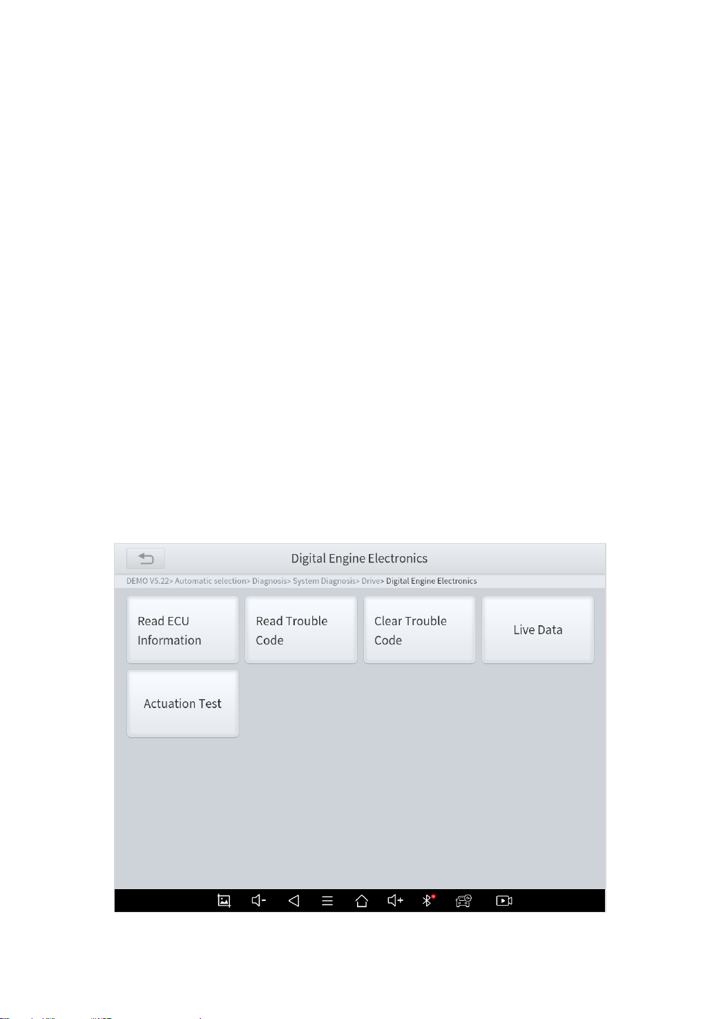
DIAGNOSE FUNCTIONS
The diagnosis system supports 5 basic diagnosis functions:
⚫ Read ECU Information
⚫ Read/Clear Trouble Code
⚫ Read Live Data
⚫ Actuation Test (Bi-Directional Control)
⚫ Freeze Frame
41
Fig 5-3
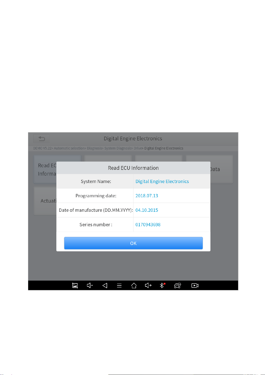
◼ Read ECU Information
This function is to read ECU version information, which is the
equivalent of "System Identification" or "System information” in
some electronic control systems, which means to read ECU related
software and hardware versions, models and production date of
diesel engine, part number, etc.
Fig 5-4
42
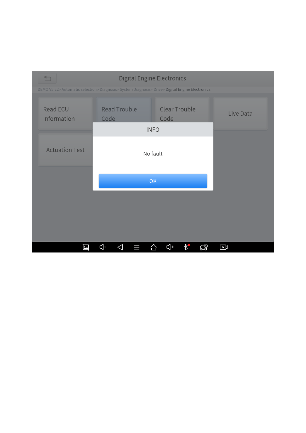
◼ Read Trouble Code
Read trouble codes that’s stored in ECU.
Fig 5-5
In the process of diagnosis, if the device shows “System is OK” or “No Trouble
Code”, it means there is no related trouble code stored in ECU or some troubles are
not under the control of ECU, most of these troubles are mechanical system troubles
or executive circuit troubles, it is also possible that signal of the sensor may bias within
limits, which can be judged in Live Data.
43
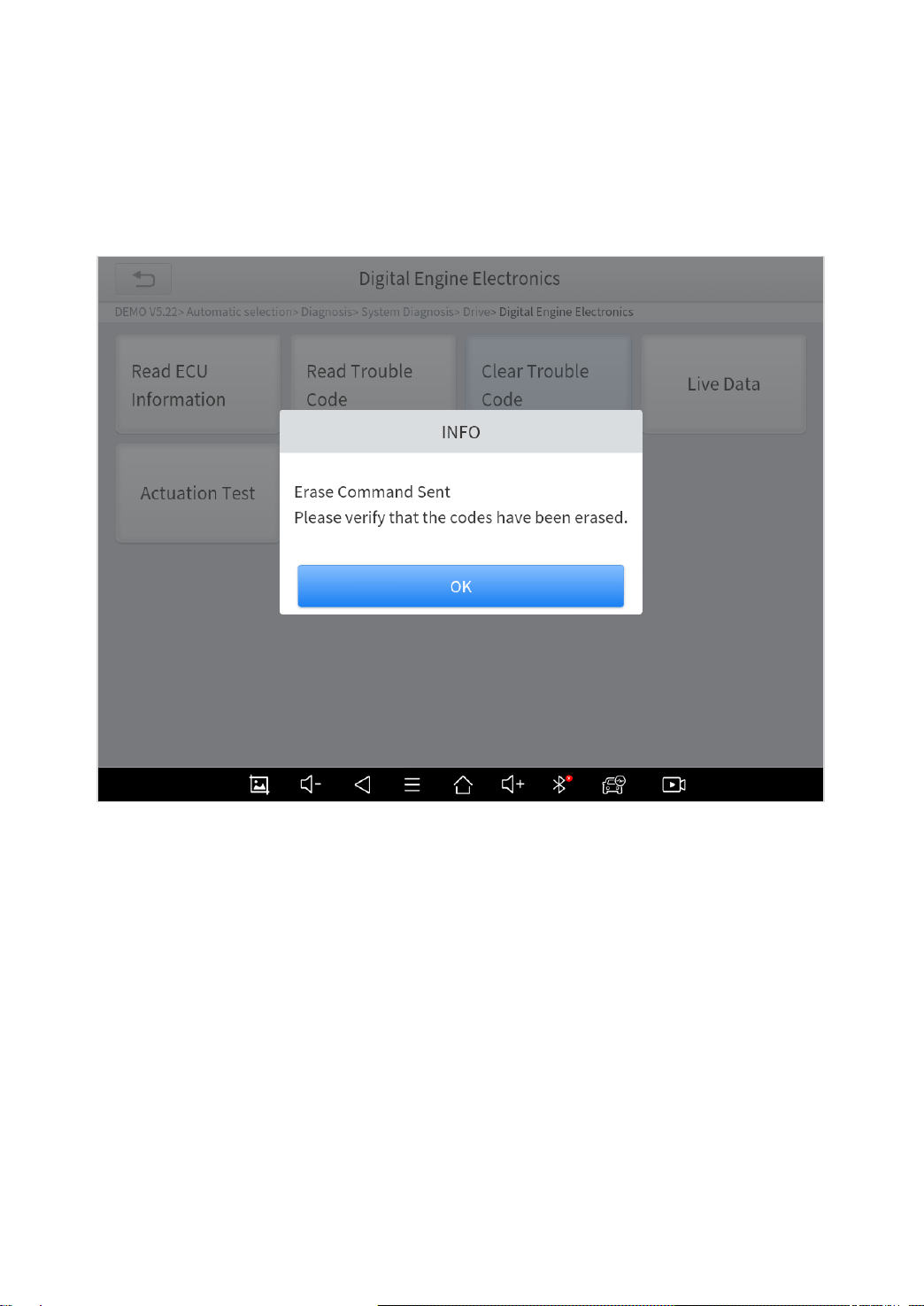
◼ Clear Trouble Code
It allows to clear current and historical trouble codes memory in
ECU, under the premise that all the troubles are eliminated.
Fig 5-6
The trouble codes can’t be erased without eliminating all the troubles, which will
cause the diagnostic tool always reading the trouble code because the code will
always be saved in ECU.
◼ Read Live Data
That is to read the parameters of the system, like for engine
diagnosis, there are parameters like oil pressure, temperature,
engine speed, fuel oil temperature, coolant temperature, intake air
temperature, etc. Based on these parameters, we can judge directly
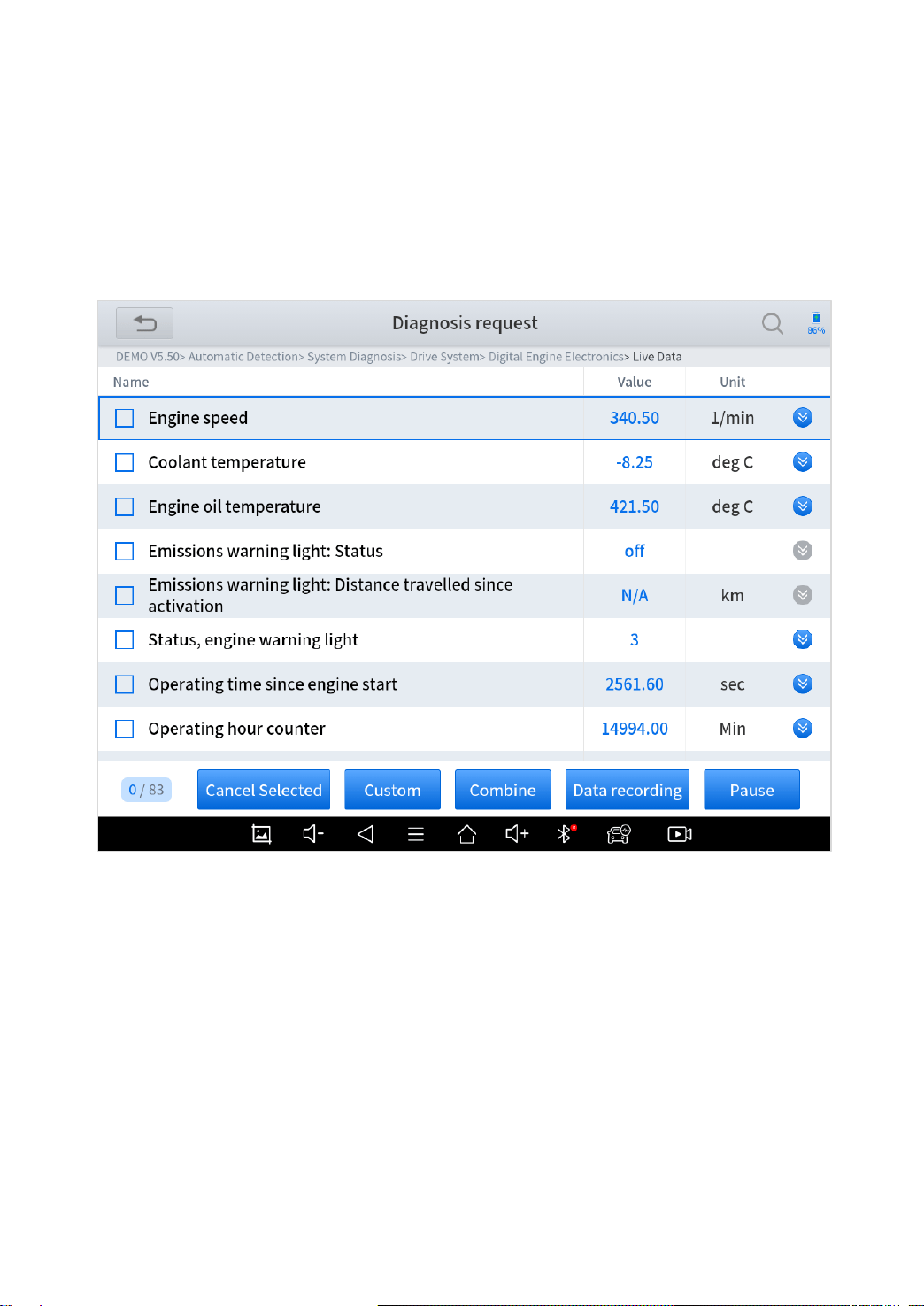
44
where the problem lies, which helps to narrow the scope in
maintenance. For some vehicles, during their actual operation, the
problems such as performance characteristics offset, sensitivity
reduction, can be judged in live data.
Fig 5-7
You can also customize the data playback through the buttons on
the screen.
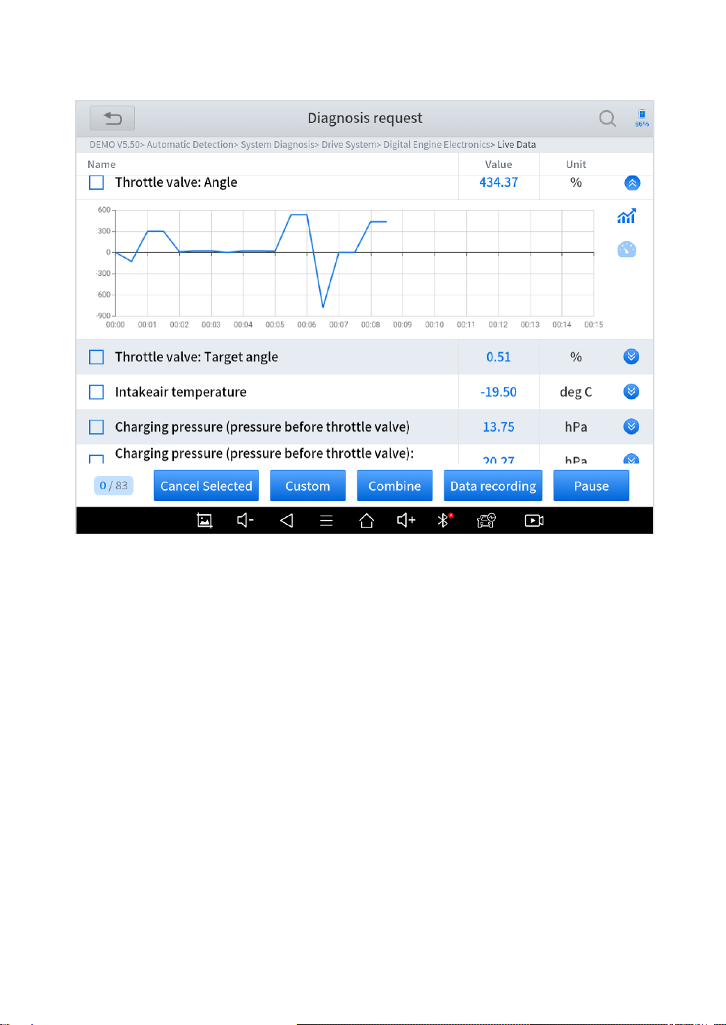
Show data graphs: There is a mark on the right side for each PIDs
(beside the PIDs that shows status). Click it to check the graphs of
the data from the PID.
45
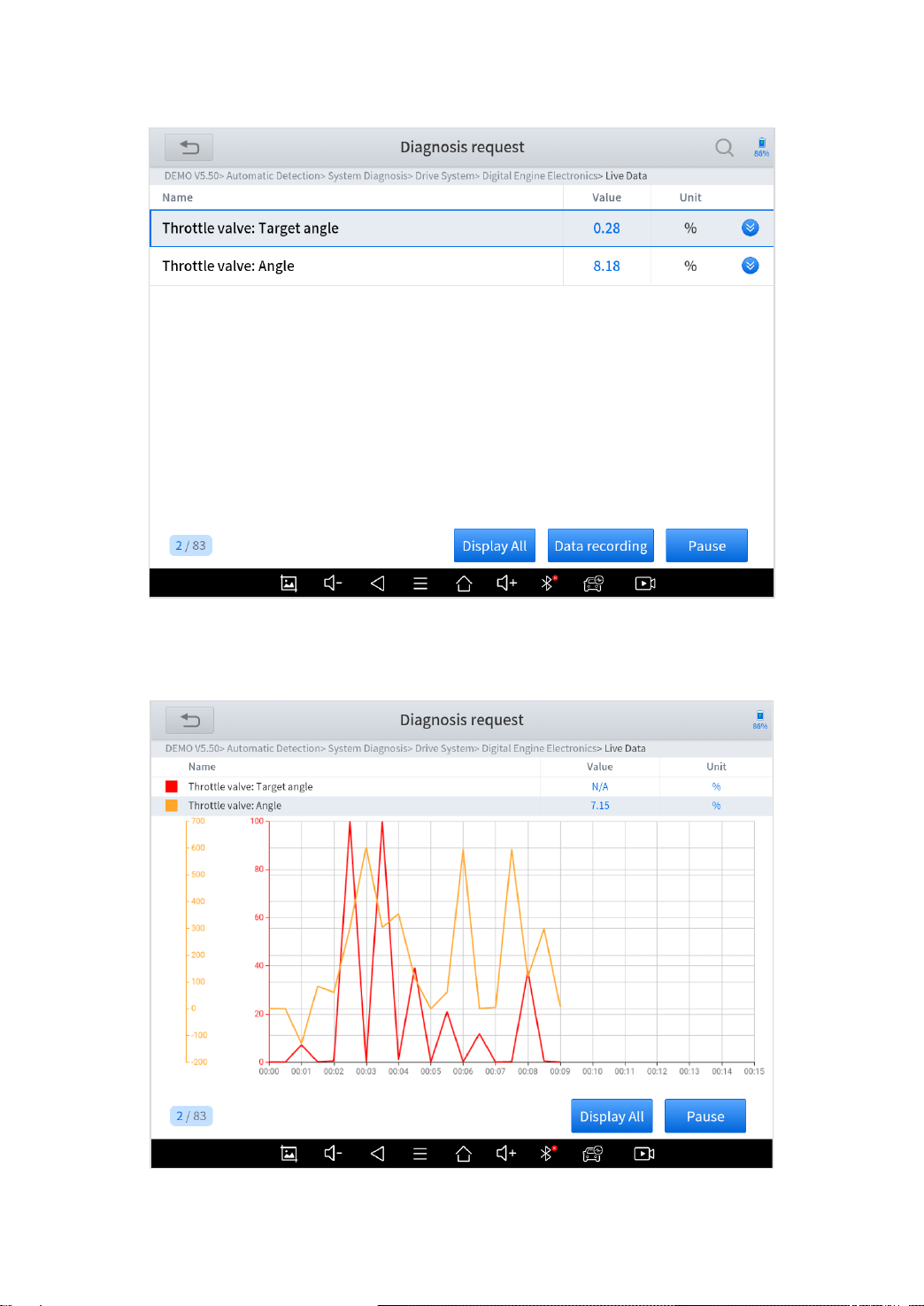
Custom: Select any of the PIDs you want to select by ticking the box
on the left, click “Custom”, and it will show only the PIDs you
selected. When you are checking custom PIDs, you can click
“Display all” and get back to show all PIDs.
46
Combine: Select the PIDs you want to check, click “Combine” to
show all the data from the PIDs in one graph.
47
Data recording: Click this button to start record the data of the PIDs.
When recording, the button will flicker, and you can click it again to
stop recording. You can check the saved records in Report – Data
Playback.
Pause: Stop refreshing the PIDs and all the live data will be frozen
when you click this button.
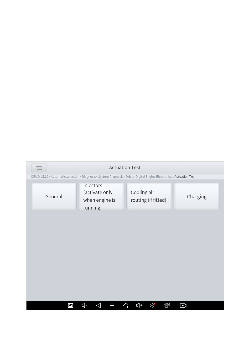
◼ Actuation Test
Actuation test, also known bidirectional control, is a generic term
used to describe sending and receiving information between one
device and another.
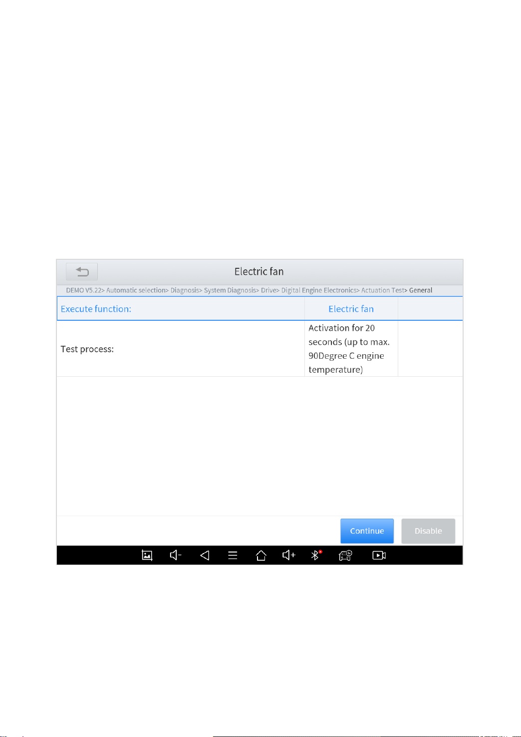
48
Fig 5-8
The vehicle engineers responsible for designing computer control
systems programmed them so a scan tool could request information
or command a module to perform specific tests and functions. Some
manufacturers refer to bidirectional controls as functional tests,
actuator tests, inspection tests, system tests or the like.
Reinitialization and reprogramming also can be included in the list
of bidirectional controls.
Fig 5-9
This function allow device sends information to, and receives
information from, vehicle control modules. For example, in the case
of OBD II generic information Mode 1 (which relates to data

49
parameters), the scan tool user initiates a request for information
from the powertrain control module (PCM), and the PCM responds
by sending the information back to the scan tool for display. Most
enhanced scan tools also have the ability to actuate relays, injectors
and coils, perform system tests, etc. Users could check the
individual part to see what is working properly by actuation test.
◼ Freeze Frame
When the signal of the sensor is abnormal, the ECU will save the
data at that moment of failure to form a freeze frame. It is usually
used to analyze the reasons that may lead to car failures.
The living data items supported by vehicles of different brands are
not exactly the same, so the freeze frames displayed when
diagnosing vehicle of different brands may also be different. Some
vehicles may not have the option of freeze frame, because the
model does not support this function.
50
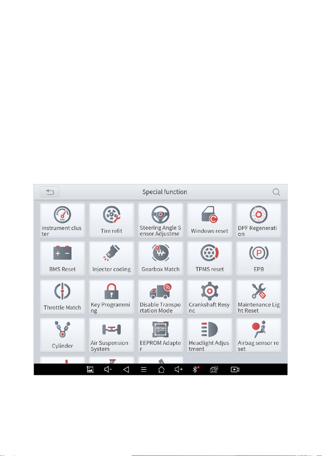
6 SPECIAL FUNCTIONS
X100PAD3 Auto Key Programmer also supports 23 commonly used
special reset functions, allowing you to quickly access your vehicle
system for various scheduled services, maintenance and reset
performance, eliminating the need to reset after resolving common
problems. This user manual lists some of the commonly used
special reset services for your reference. The special functions
interface is shown as below:
Fig 6-1
Due to the limitation of screenshots, the special functions shown in this picture are not
complete.

51
All special functions supported by X100PAD3 are subject to the actual special functions
displayed on the device.
Please make sure the vehicle you’re working on supports the original functions.
OIL LIGHT RESET
Reset the Engine Oil Life System, which calculates the optimum oil
life change interval based on the vehicle's driving conditions and
climate. The oil life reminder must be reset each time the oil is
changed so that the system can calculate when the next oil change
is required.
This function allows you to perform reset for the engine oil life
system, which calculates an optimal oil life change interval
depending on the vehicle driving conditions and climate.
This function can be performed in the following cases:
⚫ If the service lamp is on, you must provide service for the car.
After service, you need to reset the driving mileage or driving
time so that the service lamp turns off and the system enables
the new service cycle.
⚫ After changing engine oil or electric appliances that monitor oil
life, you need to reset the service lamp.

52
EPB
Electronic Parking Brake (EPB) System reset is a popular special
function. You can use this function to reset the electronic parking
brake system and brake pads, which also supports the brake pad
replacement (retraction, release of the brake pump), G-sensor and
body angle calibration. This function has multiple uses and can
safely and effectively maintain the electronic brake system. These
applications include deactivating and activating brake control
systems, assisting in controlling brake fluid, opening and closing
brake pads, and setting brakes after replacing brake discs or brake
pads, etc.
1. If the brake pad wears the brake pad sense line, the brake pad
sense line sends a signal sense line to the on-board tablet to
replace the brake pad.
After replacing the brake pad, you must reset the brake pad.
Otherwise, the car alarms.
2. Reset must be performed in the following cases:
⚫ The brake pad and brake pad wear sensor are replaced.
⚫ The brake pad indicator lamp is on.
⚫ The brake pad sensor circuit is short, which is recovered.
⚫ The servo motor is replaced.

53
SAS
Steering Angle Sensors (SAS) System Calibration permanently
stores the current steering wheel position as the straight-ahead
position in the SAS EEPROM. Therefore, the front wheels and the
steering wheel must be set exactly to the straight-ahead position
before calibration. In addition, the VIN is also read from the
instrument cluster and stored permanently in the SAS EEPROM.
On successful completion of calibration, the SAS fault memory is
automatically cleared.
To reset the steering angle, first find the relative zero-point position
for the car to drive in straight line. Taking this position as reference,
the ECU can calculate the accurate angle for left and right steering.
After replacing the steering angle position sensor, replacing
steering mechanical parts (such as steering gearbox, steering
column, end tie rod, steering knuckle), performing four-wheel
alignment, or recovering car body, you must reset the steering angle.
DPF
The Diesel Particle Filter (DPF) function manages DPF
regeneration, DPF component replacement teach-in and DPF
teach-in after replacing the engine control unit.
The ECM monitors driving style and selects a suitable time to
employ regeneration. Cars driven a lot at idling speed and low load

54
will attempt to regenerate earlier than cars driven more with higher
load and speed. For regeneration to take place, a prolonged high
exhaust temperature must be obtained.
In the event of the car being driven in such a way that regeneration
is not possible, i.e., frequent short journeys, a diagnostic trouble
code will eventually be registered in addition to the DPF light and
“Check Engine” indicators displaying. A service regeneration can be
requested in the workshop using the diagnostic tool.
DPF regeneration is used to clear PM (Particulate Matter) from the
DPF filter through continuous combustion oxidation mode (such as
high temperature heating combustion, fuel additive or catalyst
reduce PM ignition combustion) to stabilize the filter performance.
DPF regeneration may be performed in the following cases:
⚫ The exhaust back pressure sensor is replaced.
⚫ The PM trap is removed or replaced.
⚫ The fuel additive nozzle is removed or replaced.
⚫ The catalytic oxidizer is removed or replaced.
⚫ The DPF regeneration MIL is on and maintenance is performed.
⚫ The DPF regeneration control module is replaced.
BMS RESET
The Battery Management System (BMS) allows the scan tool to
evaluate the battery charge state, monitor the close-circuit current,

55
register the battery replacement, and activate the rest state of the
vehicle.
This function enables you to perform a resetting operation on the
monitoring unit of vehicle battery, in which the original low battery
fault information will be cleared and battery matching will be done.
Battery matching must be performed in the following cases:
⚫ Main battery is replaced. Battery matching must be performed
to clear original low battery information and prevent the related
control module from detecting false information. If the related
control module detects false information, it will invalidate some
electric auxiliary functions, such as automatic start & stop
function, sunroof without one-key trigger function, power window
without automatic function.
⚫ Battery monitoring sensor. Battery matching is performed to re-
match the control module and motoring sensor to detect battery
power usage more accurately, which can avoid an error
message displaying on the instrument panel.
THROTTLE
Throttle Position Sensor (TPS) Match, this function enables you to
make initial settings to throttle actuators and returns the “learned”
values stored on ECU to the default state. Doing so can accurately
control the actions of regulating throttle (or idle engine) to adjust the
amount of air intake.

56
TPMS RESET
Tire Pressure Monitor System (TPMS) Reset allows you to quickly
look up the tire sensor IDs from the vehicle ECU, as well as to
perform TPMS replacement and reset procedures after tire sensors
are replaced.
This function allows you to quickly look up the tire sensor IDs from
the vehicle’s ECU, as well as to perform TPMS replacement and
sensor test.
⚫ After the tire pressure MIL turns on and maintenance is
performed, the tire pressure resetting function must be
performed to reset tire pressure and turn off the tire pressure
MIL.
⚫ Tire pressure resetting must be performed after maintenance is
performed in the following cases: tire pressure is too low, tire
leaks, tire pressure monitoring device is replaced or installed,
tire is replaced, tire pressure sensor is damaged, and tire is
replaced for the car with tire pressure monitoring function.
ABS BLEEDING
Anti-lock Braking System (ABS) Bleeding allows you to perform
various bi-directional tests to check the operating conditions of ABS.

57
1. When the ABS contains air, the ABS bleeding function must be
performed to bleed the brake system to restore ABS brake
sensitivity.
2. If the ABS tablet, ABS pump, brake master cylinder, brake
cylinder, brake line, or brake fluid is replaced, the ABS bleeding
function must be performed to bleed the ABS.
3. After the oil in the brake oil tank is seriously insufficient or the
brake fluid is replaced, ABS Bleeding is also required
When performing ABS Bleeding, it is necessary to unscrew the exhaust screw of the
ABS pump.
After completing the tire pressure sensor learning, it takes a while for the fault light to
go out.
Tire pressure imbalance will also cause the tire pressure light to light up.
INJECTOR CODING
This function can write the identification code of the fuel injector into
the ECU so that the ECU can recognize and work normally. Write
injector actual code or rewrite code in the ECU to the injector code
of the corresponding cylinder so as to more accurately control or
correct cylinder injection quantity.
After the ECU or injector is replaced, injector code of each cylinder
must be confirmed or re-coded so that the cylinder can better
identify injectors to accurately control fuel injection.
After cleaning, generally there is no need to do the coding matching function.
The identification of the fuel injector includes its working accuracy value and type value.
When replacing it, you need to find the corresponding model for replacement.

58
At present, mainstream cars support injector coding function
GEARBOX MATCH
After changing the gearbox or changing the gearbox ECU, you need
to use the gearbox matching function to re-match the engine and
the gearbox.
*Cautions!
Before resetting the gearbox, please check the gearbox control unit
to ensure that there is no fault code. If there is a fault code, the
gearbox memory function cannot be reset. Please road test after
reset.
SUSPENSION
This function can adjust the height of the vehicle body. When
replacing the body height sensor in the air suspension system, or
control module or when the vehicle level is incorrect, you need to
perform this function to adjust the body height sensor for level
calibration.
The air suspension system reset function enables the tablet ECU to
match the current air suspension system information, thereby
ensuring the normal damping effect of the vehicle when driving.
Application scenarios:
⚫ The shock absorber is not the same height due to air leakage,
maintenance, replacement, etc.;

59
⚫ After replacing the air pump assembly;
⚫ After replacing the electronic control module.
WINDOWS INITIALIZATION
This function is to match the windows to restore the initial memory
of the ECU and restore the automatic raising and lowering functions
of the power window. Usually when the vehicle window fails or after
replacing the window glass, we need to use this function to initialize
the car window.
SEAT CALIBRATION
This function is suitable for the matching of replacement and
maintenance seats with memory function. After the seat fails or is
replaced or repaired, it is generally necessary to use this function to
match the seat.
Needed for cars with seats with memory function, general gasoline cars don’t need.
HEADLIGHT
This function is used to initialize the adaptive headlight system. It
refers to the adaptive front lighting system (when using bi-xenon
headlights at night), it can be rotated to the sides, pressing the
button means that they remain direct, and do not turn when you turn.
After replacing the headlights, the adaptive headlight system needs
to be matched.

60
A/F RESET
This function is applied to set or learn Air/Fuel ratio parameters.
STOP/START RESET
This function is used to open or close the automatic start-stop
function via setting the hidden function in ECU (provided that the
vehicle has a hidden function and supported by hardware).
AIRBAG RESET
Supplemental Restraint System (SRS) Reset allows you resets the
airbag data to clear the airbag collision fault indicator. Generally,
SRS reset is required after airbag replacement
INSTRUMENT CLUSTER
This function allows you to copy, write or rewrite the kilometers in
the odometer chip by using the car diagnostic tablet and data cable,
so that the odometer can display the actual mileage.
61
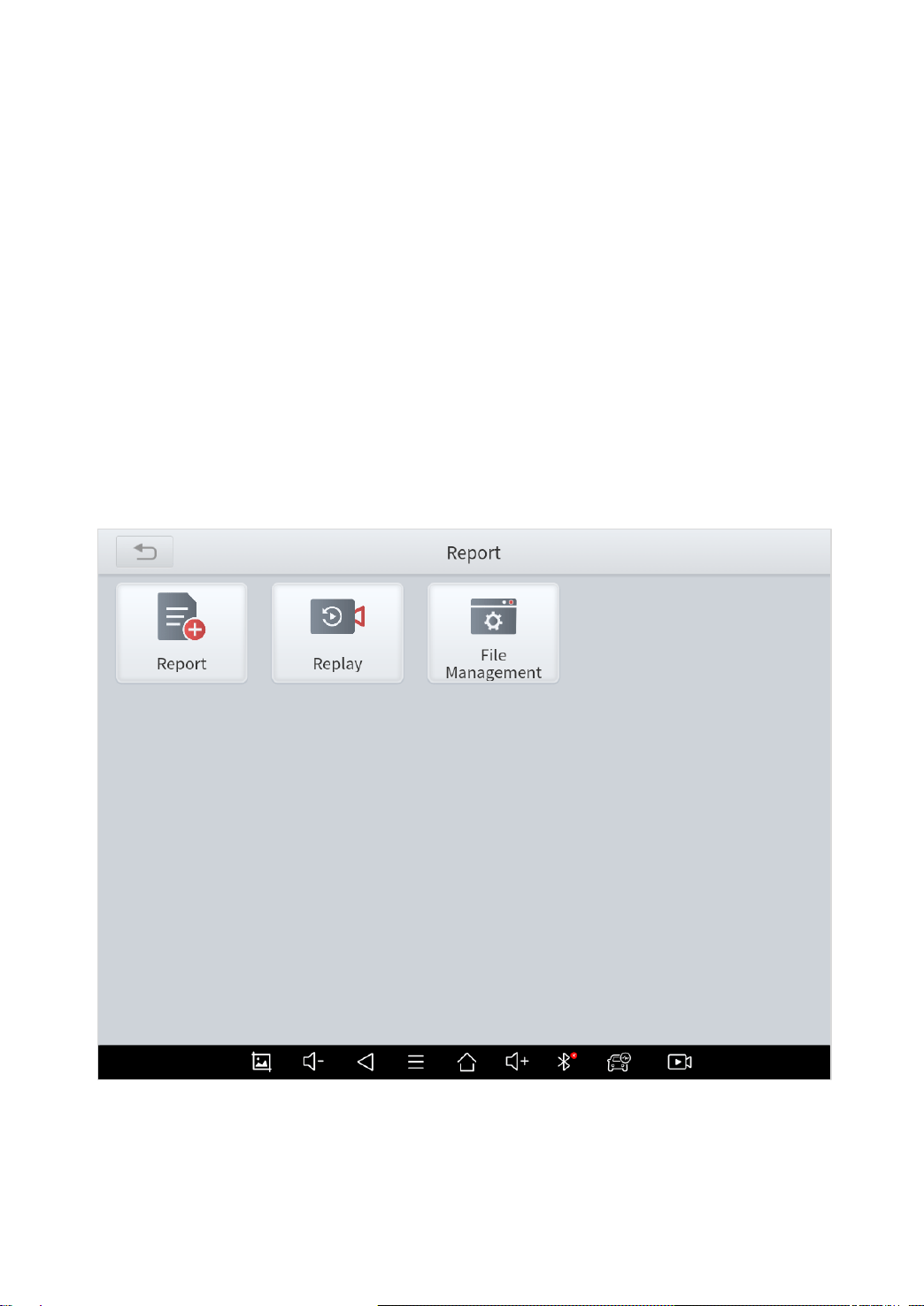
7 REPORT
Diagnostic Report is used for viewing and printing the saved files,
such as Live Data, Trouble codes or pictures generated in the
process of diagnosis, users also can view a record of which cars
have been previously tested. It includes 3 parts:
⚫ Report
⚫ Replay
⚫ File Management
Fig 7-1
62
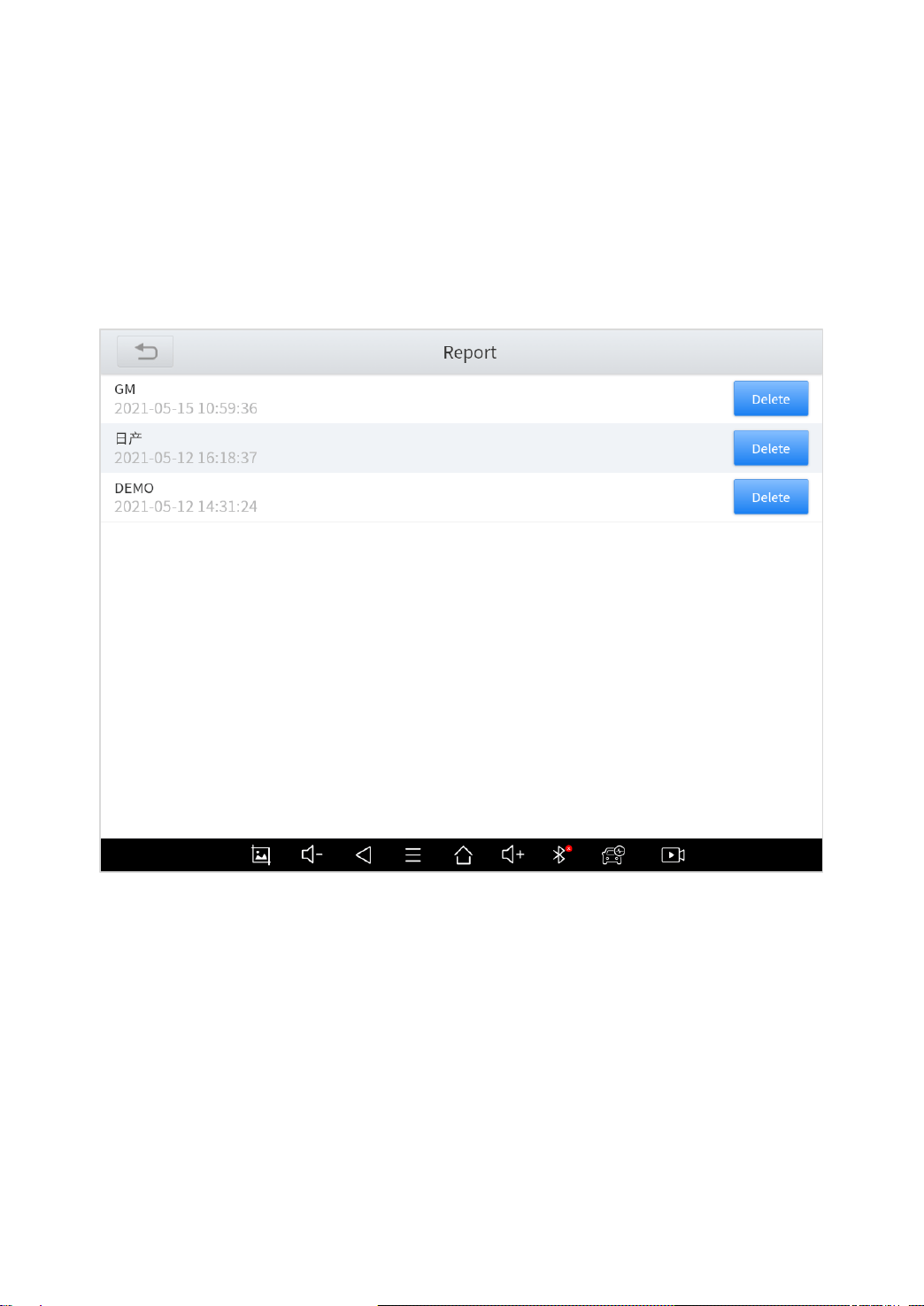
REPORT
This feature provides a history of diagnostic reports, where you can
view and delete the vehicle's diagnostic reports according to your
needs.
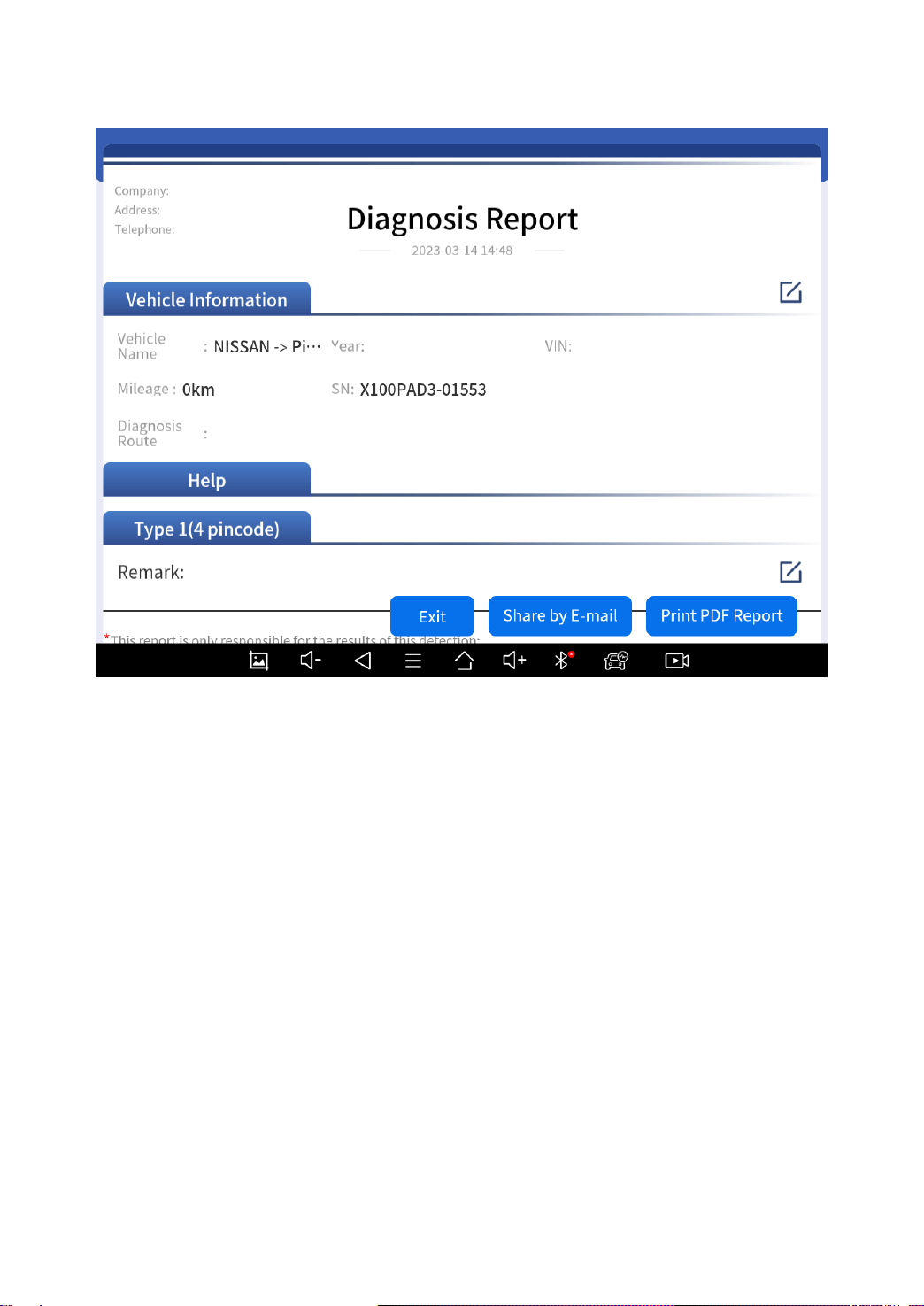
Fig 7-2
When you open the report, located in the header of the table is the
studio information you filled in advance in the system setup, then
the information of the vehicle, including the diagnosis date and time,
VIN number, vehicle brand, diagnosis path, etc., as shown as below:
63
Fig 7-3
◼ Share by E-mail
You can share the diagnosis report to your E-mail address. To do
that, click “Share by E-mail” button, input the email address that you
are going to send the report to, and click “Send”. The diagnosis
report will be sent to the address soon.
◼ Print PDF Report
As you can see, you also could click " Print PDF Report " at the
bottom right corner to output the pdf report. If you need to close the
report, you could tap on the button “Exit”.
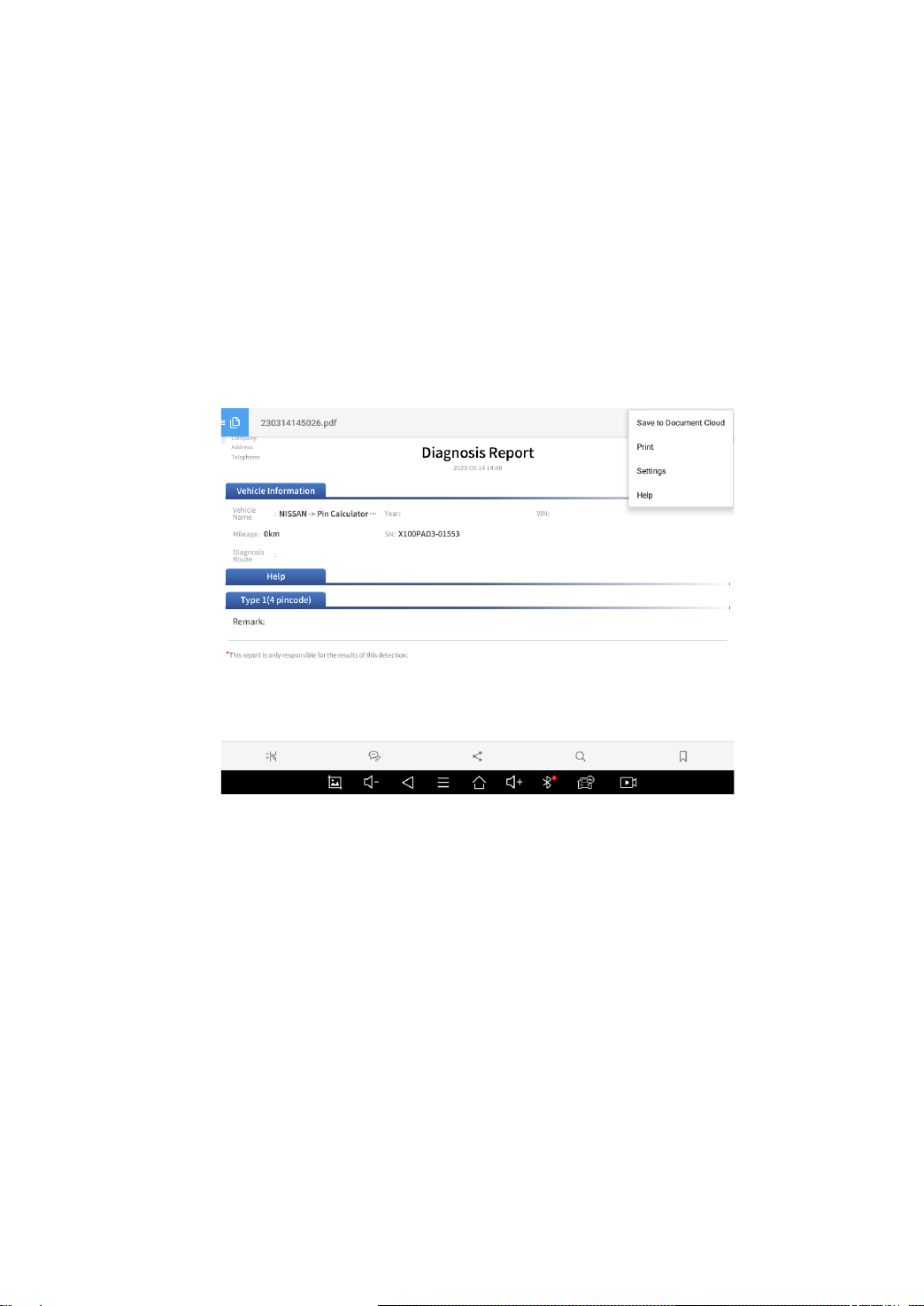
Please follow below steps to print your report▼
64
Step 1: Install an APP that can drive your target printer. Add the
printer and input the IP address of the printer in the APP, or you can
contact your dealer for help.
Step 2: Back to Android main menu, go to Settings -> Printing->
Turn printer on.
Step 3: Report-> Choose report-> Print PDF Report-> Print
Fig 7-4
Step 4: Click the top-left corner of the screen and choose the printer
you added before. Then click the button on the right to print.
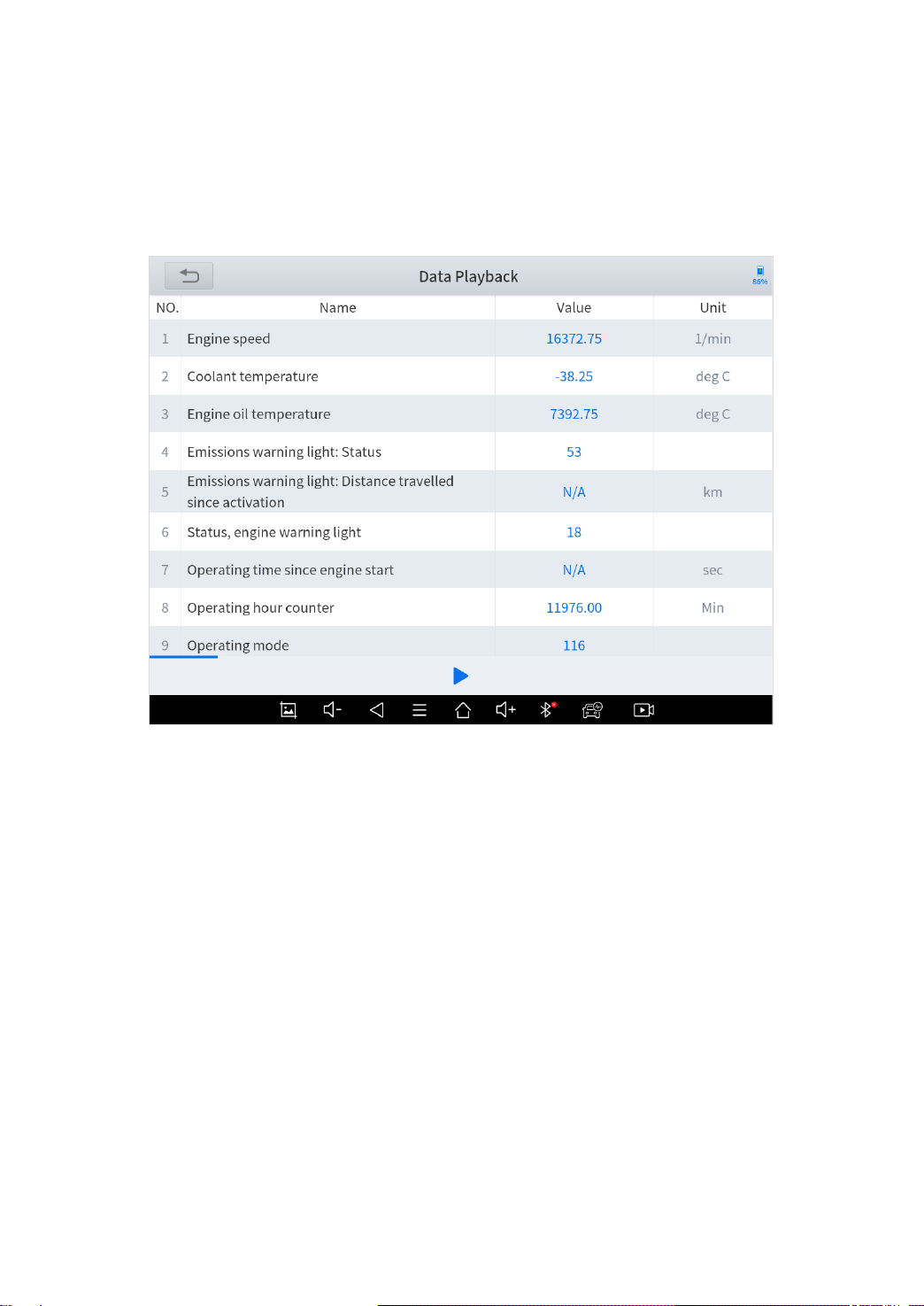
DATA PLAYBACK
This function allows you to replay the living data recorded during the
diagnosis process.
65
Before replaying the living data, please make sure you double
clicked on "Data recording" button during diagnosis process. (See
Diagnosis – Diagnose functions – Live Data section)
FILE MANAGER
This function allows you to check and delete files in the device.
Please use this function under the guidance of professionals.
Ordinary users are not recommended to use it by themselves, as it
may cause software missing or malfunctioning.

66
8 SETTINGS
Click the Settings button to adjust the default settings and view the
information of X100PAD3 Auto Key Programmer. There are several
options available in the system settings:
⚫ Language
⚫ Units
⚫ Workshop Information
⚫ Firmware Information
⚫ About
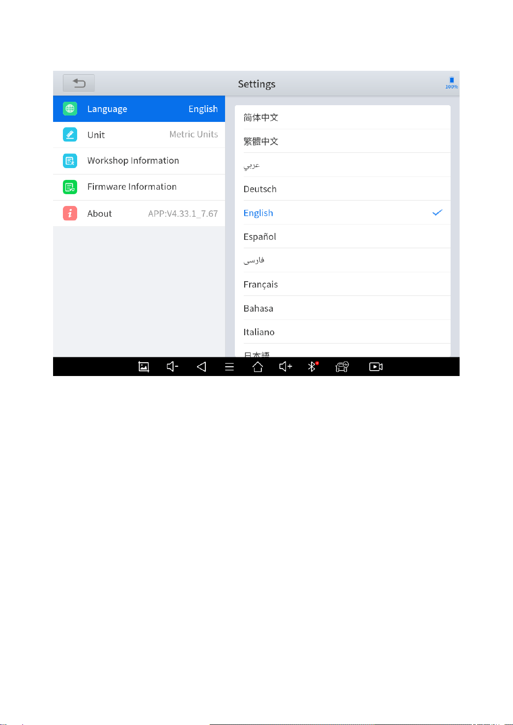
LANGUAGE
The languages supported by this device are listed in Settings. In
areas outside the English area, the default language is English and
the local official language. Users can switch between English and
local official languages on the device by themselves. If you need to
switch other languages, please contact the dealer to unbind the
current language configuration and rebind it to the language
configuration you need to switch. After the configuration is
successfully changed, you can switch the target language.
67
Fig 8-1
This will only change the language of the APP. If you want to change system
language, please go to Android Settings.
◼ How to change the language of your software?
Step1: Contact your dealer and leave a message about the
language you need and the S/N of your device
Step2: Settings->Language->Choose language
Step3: OS Settings->Language & input->Choose Language
Step4: Back to Upgrade
68
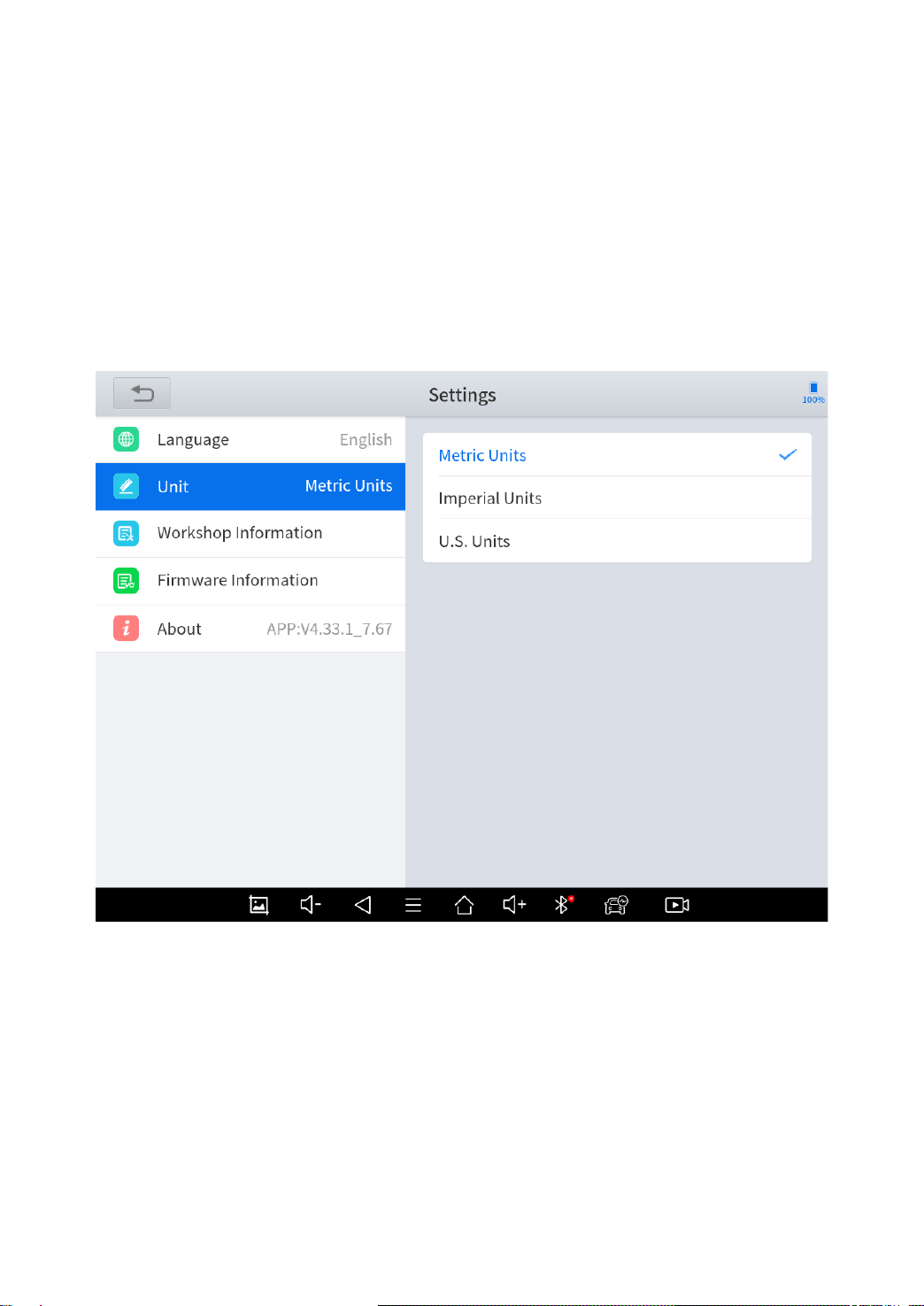
UNITS
You can switch the unit used by the system. X100PAD3 provides
you with metric and imperial units.
You can directly click on the unit when you need, after the switch is
successful, a blue check mark will be shown behind the unit’s name.
Fig 8-2
MY WORKSHOP INFO
Click on My Workshop Information, you can input your workshop
information here. As shown in the figure below, you just need to fill
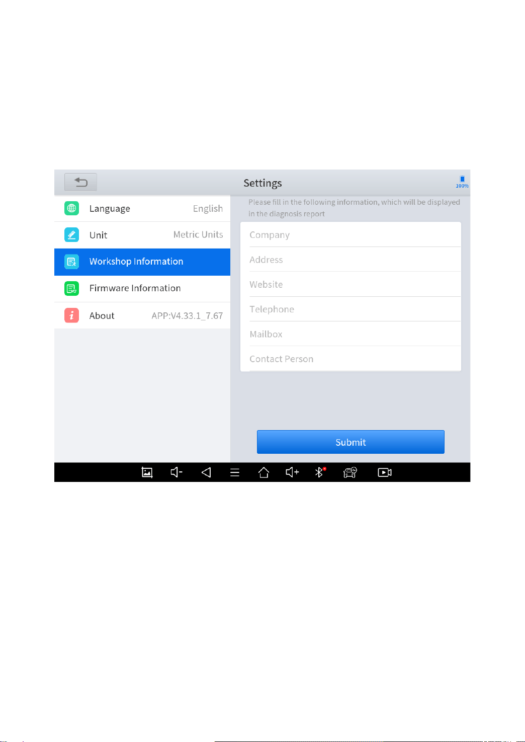
69
in the valid information in the corresponding column and click
"SUBMIT". And then it will show your workshop information in the
report when you generate a diagnostic report, including your
company name, address, website, telephone, and mailbox.
Fig 8-3
FIRMWARE INFORMATION
From here you can check the version of the firmware inside the
device.
When you are not able to enter the software and shows “VCI connection failed”, we
suggest to check here and see if the firmware has been loaded properly.
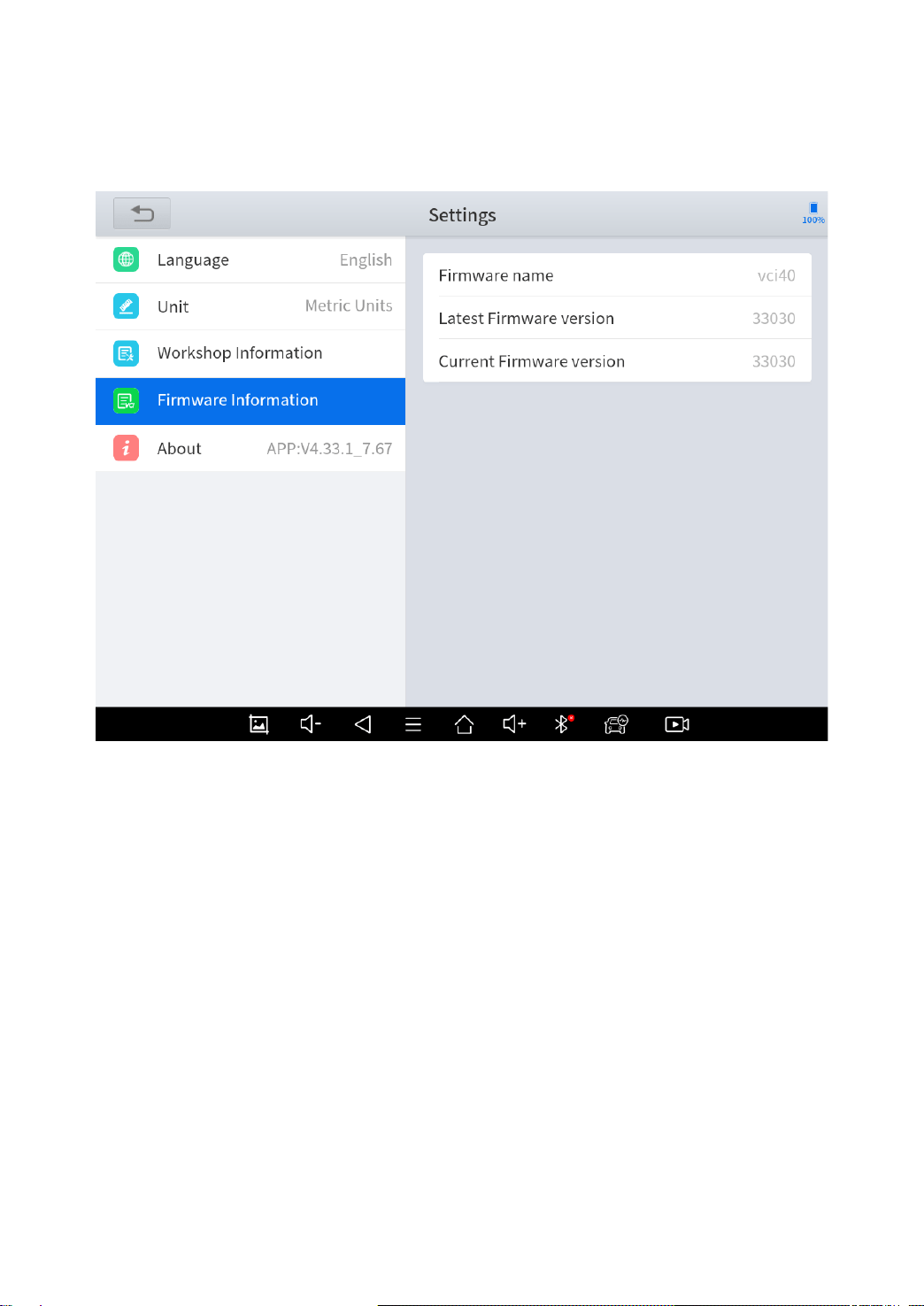
70
The firmware version will not show directly when you are checking. Normally you can
see the version numbers after a while.
71
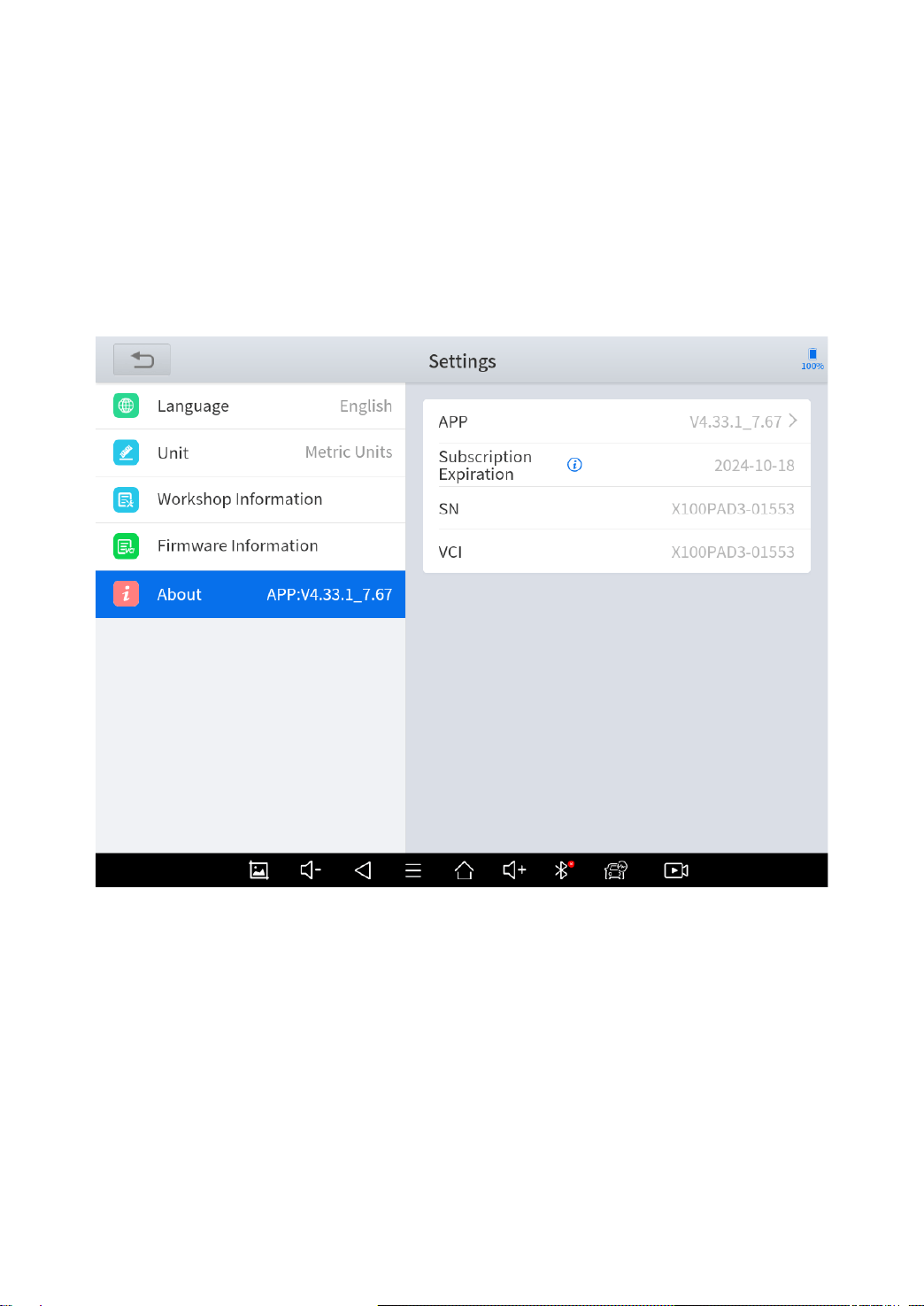
ABOUT
From ABOUT, you can check the serial number, update expiration
date and APP version here.

72
9 REMOTE ASSISTANCE
Tap on "Remote" to start the TeamViewer quick support program,
which is a simple, fast, and secure remote-control screen. You can
use this application to enable them to control your tablet on a PC
through the TeamViewer software, thereby obtaining temporary
remote support from Xtool technical support center.
Tablets and mobile devices running TeamViewer are identified by a
globally unique ID. When the remote application is started for the
first time, the ID will be automatically generated according to the
hardware characteristics and will not be changed in the future. This
TeamViewer ID can individually access all TeamViewer clients.
Before launching the remote desktop application, make sure that
the tablet is connected to the Internet so that you can access the
tablet to receive remote support from a third party. If you encounter
problems and are not able to solve them, you could open this
application and ask for remote assistance.
To obtain remote support from your partners or Xtool After-service
Center:
1. Turn on the power of the tablet.
2. Click Remote in the diagnosis application. The TeamViewer
screen is displayed, and the device ID will be generated.
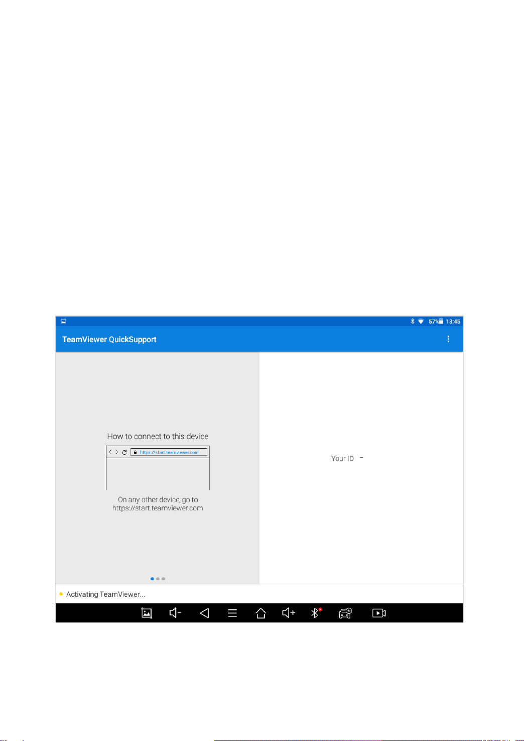
73
3. Your partner must install the remote-control software on his/her
tablet by downloading the full version of TeamViewer program
(http://www.teamviewer.com) online, and then start the software on
his/her tablet at the same time, in order to provide support and
remote control of the tablet.
4. Provide your ID to the partner or Xtool technician, and then wait
for him/her to send you a remote-control request.
5. A pop-up window will be shown for asking you to confirm to allow
the remote-control program to control your device.
6. Click Allow to accept, or click Reject to reject.
Fig 9-1

74
10 TROUBLESHOOTING
1) Q: I want to reset this device.
A: Please go to Android settings – Backup & reset – Factory reset.
Before you reset, make sure you are still in subscription. This will
delete all the software and you cannot download any software if
you are out of subscription.
2) Q: I can’t get in software, and it shows “License exception”.
A: If this only happened on some of the software, click the
software and hold it until it shows a box and delete button above.
Choose the software and delete it, then go to updates and re-
install this software and see if it works.
If this happened on all the software, try reset this device. And if
it still doesn’t work, please contact Xtool aftersales services.
3) Q: I can’t get in any of the software, and it shows “VCI
connection failed”.
A: Please go to APP Settings – Firmware Information and wait.
If it shows failed, take a screenshot and contact Xtool aftersales
services.
4) Q: I can’t get in some of the software, and it shows “Failed”.
A: Delete and re-install the software.

75
5) Q: My device keeps telling me to sync the device and it can’t
get into the app.
A: Connect it to Internet, wait for about 15min, then try again. If
this still happened, contact Xtool aftersales services.
6) Q: I go to update menu and check updates, but it shows “Not
supported for this language”.
A: Please go to APP Settings and select the language back or
select English. If these are not the language you wanted, please
contact your dealer and tell them about the language you want.
After that, remember to check updates again to download all the software or the
menus will show blank.
7) Q: I can’t turn on the device when charging.
A: Press the power button to light up the screen (showing the
charging status) first. Then press and hold the power button for
4-5 seconds until the boot animation is shown on screen.
8) Q: I can’t send the files to my iPhone via Bluetooth.
A: Currently we can’t send files to iOS devices via Bluetooth. Try
wire connection or send files via Internet.
9) Q: I can’t connect the device to Wifi.

76
A: Currently we don’t support hotspots with Wifi 6 or with WPA3
safety protocols. Please try change a network or change the
settings of the router.
10) Q: My device is out of storage space, and I can’t
download the software.
A: There are multiple ways to clear your storage space:
1. (Recommended) Delete some of the software you
don’t need. See 2) to check how to delete software.
2. (Recommended) Go to Report – File Manager –
Storage of diagnosis details, click edit button on the
top-right corner of the screen, select Download folder
and delete it. After that, please download the software
packs one by one.
3. Factory reset the device, and tick “Erase SD card”
before you start. Before you do that, make sure you
are in subscription and can download the software
updates.
Also if you meet these issues frequently, you can
avoid them by regularly delete some of the software
that are not commonly used or delete download folder
regularly and do not download too many of them.
11) Q: I can’t connect my vehicle and it says “Communication
failed”.

77
A: Please check following these orders.
1. Contact your dealer to confirm whether the vehicle
model is supported by the scan tool you owned.
2. Check whether the vehicle is properly connected (e.g.
whether the ignition is ON, and the diagnosis of some
vehicles need to turn on the engine).
3. Confirm whether you have entered the correct
diagnosis menu.
4. Confirm whether the AUTO-SCAN function can assist
you to enter the correct diagnosis menu, or whether
the OBDII diagnosis function works.
5. Check whether the software is the latest version, if not,
please update to the latest version first.
6. If all are checked and it is still not done, please contact
your dealer or Xtool aftersales services.
12) Q: I can’t connect to KC100 or KC501.
A: Please check following these orders.
1. Check the cables. We suggest to use our original
cables for KC100 and KC501, and some aftermarket
cables may not support data transferring.
2. Check if the lights on KC100 or KC501 are on. If not,
connect it to other devices (like PC, etc.) and see if
the lights are on.

78
For KC501s you can also check it by connect it to a 12V power
supply.
If the lights are on when connecting to other devices,
please check the HDMI port of the tablet and see if it
is damaged, take a photo and contact your dealer.
3. If on, connect the tablet to PC and see if the tablet can
be recognized. If not, please contact your dealer.
13) Q: My KC100/KC501/KS-1 shows bound by other devices.
A: Please note that these components are bound to tablets
when you are using it for the first time. If you need to use it on
other devices, please contact Xtool aftersales services.
14) Q: I am using KC100/KC501, but it tells me not supported.
A: Please go to update menu and see if you have downloaded
KC501LIB. This is necessary when using these devices.
15) Q: Some of the software are missing in my device.
A: Please make sure you are using the language that
supported in your area (see 6)), and your subscription is still not
expired. If you have checked, please go to updates and check if
you have downloaded these software.
Some of the regional software is not supported in your area. Please contact
your dealer for details.

79
16) Q: I can’t activate my device and it keeps telling me failed.
A: There are 2 situations for this issue.
1. For ‘Activation Failed’
Generally caused by network instability, please switch
to a more stable network and try to activate again.
2. For ‘Registration Failed’
Generally, it is caused by the connection timeout or
the sending timeout, please check whether you have
blocked the outgoing network traffic to non-US
regions like China. We recommend that you unblock
and try to register again.
If you have checked it’s all clear but you still can’t
register, please contact Xtool aftersales services and
tell us your serial numbers.

80

81
SHENZHEN XTOOLTECH INTELLIGENT CO., LTD
Company address: 17&18/F, Building A2, Creativity City, Liuxian Avenue, Nanshan
District, Shenzhen, China
Factory address: 2/F, Building 12, Tangtou Third Industrial Zone, Shiyan Street,
Baoan District, Shenzhen, China
Service Hotline: 0086-755-21670995/86267858
Email: marketing@Xtooltech.com
Fax: 0755-83461644
Website: www.Xtooltech.com