
i
Trademarks
Autel
®
and MaxiIM
®
are trademarks of Autel Intelligent Technology Corp., Ltd.,
registered in China, the United States and other countries. All other marks
are trademarks or registered trademarks of their respective holders.
Copyright Information
No part of this manual may be reproduced, stored in a retrieval system or
transmitted, in any form or by any means, electronic, mechanical,
photocopying, recording, or otherwise without the prior written permission of
Autel.
Disclaimer of Warranties and Limitation of Liabilities
All information, specifications and illustrations in this manual are based on
the latest information available at the time of printing.
Autel reserves the right to make changes at any time without notice. While
information of this manual has been carefully checked for accuracy, no
guarantee is given for the completeness and correctness of the contents,
including but not limited to the product specifications, functions, and
illustrations.
Autel will not be liable for any direct, special, incidental, indirect damages or
any economic consequential damages (including the loss of profits).
IMPORTANT
Before operating or maintaining this unit, please read this manual carefully,
paying extra attention to the safety warnings and precautions.
For Services and Support
www.autel.com
For technical assistance in all other markets, please contact your local selling
agent.

ii
Safety Information
For your own safety and the safety of others, and to prevent damage to the
device and vehicles upon which it is used, it is important that the safety
instructions presented throughout this manual be read and understood by all
persons operating or coming into contact with the device.
There are various procedures, techniques, tools, and parts for servicing
vehicles, as well as in the skill of the person doing the work. Because of the
vast number of test applications and variations in the products that can be
tested with this equipment, we cannot possibly anticipate or provide advice
or safety messages to cover every circumstance. It is the automotive
technician’s responsibility to be knowledgeable of the system being tested. It
is crucial to use proper service methods and test procedures. It is essential
to perform tests in an appropriate and acceptable manner that does not
endanger your safety, the safety of others in the work area, the device being
used, or the vehicle being tested.
Before using the device, always refer to and follow the safety messages and
applicable test procedures provided by the manufacturer of the vehicle or
equipment being tested. Use the device only as described in this manual.
Read, understand, and follow all safety messages and instructions in this
manual.
Safety Messages
Safety messages are provided to help prevent personal injury and equipment
damage. All safety messages are introduced by a signal word indicating the
hazard level.
DANGER
Indicates an imminently hazardous situation which, if not avoided, will result
in death or serious injury to the operator or to bystanders.
WARNING
Indicates a potentially hazardous situation which, if not avoided, could result
in death or serious injury to the operator or to bystanders.

iii
Safety Instructions
The safety messages herein cover situations Autel is aware of. Autel cannot
know, evaluate or advise you as to all of the possible hazards. You must be
certain that any condition or service procedure encountered does not
jeopardize your personal safety.
DANGER
When an engine is operating, keep the service area WELL VENTILATED or
attach a building exhaust removal system to the engine exhaust system.
Engines produce carbon monoxide, an odorless, poisonous gas that causes
slower reaction time and can lead to serious personal injury or loss of life.
SAFETY WARNINGS
Always perform automotive testing in a safe environment.
Wear safety eye protection that meets ANSI standards.
Keep clothing, hair, hands, tools, test equipment, etc. away from all
moving or hot engine parts.
Operate the vehicle in a well ventilated work area, for exhaust gases are
poisonous.
Put the transmission in PARK (for automatic transmission) or NEUTRAL
(for manual transmission) and make sure the parking brake is engaged.
Put blocks in front of the drive wheels and never leave the vehicle
unattended while testing.
Be extra cautious when working around the ignition coil, distributor cap,
ignition wires and spark plugs. These components create hazardous
voltages when the engine is running.
Keep a fire extinguisher suitable for gasoline, chemical, and electrical
fires nearby.
Do not connect or disconnect any test equipment while the ignition is on
or the engine is running.
Keep the test equipment dry, clean, free from oil, water or grease. Use a
mild detergent on a clean cloth to clean the outside of the equipment as
necessary.
Do not drive the vehicle and operate the test equipment at the same time.
Any distraction may cause an accident.

iv
Refer to the service manual for the vehicle being serviced and adhere to
all diagnostic procedures and precautions. Failure to do so may result in
personal injury or damage to the test equipment.
To avoid damaging the test equipment or generating false data, make
sure the vehicle battery is fully charged and the connection to the vehicle
DLC is clean and secure.
Do not place the test equipment on the distributor of the vehicle. Strong
electro-magnetic interference can damage the equipment.

v
CONTENTS
1 USING THIS MANUAL ................................................................................. 1
CONVENTIONS ................................................................................................. 1
2 GENERAL INTRODUCTION ........................................................................ 3
MAXIIM IM608 DISPLAY TABLET ....................................................................... 3
MAXIFLASH – WIRELESS DIAGNOSTIC INTERFACE ............................................... 7
XP400 PRO .................................................................................................. 10
ACCESSORIES KIT ......................................................................................... 78
3 GETTING STARTED .................................................................................. 83
POWERING UP .............................................................................................. 83
POWERING DOWN .......................................................................................... 87
4 IMMO .......................................................................................................... 88
ESTABLISH VEHICLE COMMUNICATION ............................................................. 88
GETTING STARTED ........................................................................................ 93
VEHICLE IDENTIFICATION ................................................................................ 94
NAVIGATION .................................................................................................. 97
IMMO ........................................................................................................ 101
5 PROGRAMMING ...................................................................................... 111
PROGRAMMING............................................................................................ 111
6 DIAGNOSTICS ......................................................................................... 119
DIAGNOSIS .................................................................................................. 119
GENERIC OBD II OPERATIONS...................................................................... 133
EXITING DIAGNOSTICS.................................................................................. 137
7 SERVICE .................................................................................................. 139
OIL RESET SERVICE .................................................................................... 139
ELECTRONIC PARKING BRAKE (EPB) SERVICE ............................................... 142
STEERING ANGLE SENSOR (SAS) SERVICE ................................................... 150
DPF SERVICE ............................................................................................. 153
8 UPDATE ................................................................................................... 158
9 SETTINGS ................................................................................................ 161

vi
UNIT ........................................................................................................... 161
LANGUAGE .................................................................................................. 162
PRINTING SETTING....................................................................................... 163
NOTIFICATION CENTER ................................................................................. 164
AUTO UPDATE ............................................................................................. 165
ABOUT ........................................................................................................ 167
SYSTEM SETTINGS....................................................................................... 167
10 REMOTE DESK ........................................................................................ 169
11 DATA MANAGER ..................................................................................... 171
OPERATIONS ............................................................................................... 171
12 SHOP MANAGER .................................................................................... 176
VEHICLE HISTORY ........................................................................................ 177
WORKSHOP INFORMATION ............................................................................ 180
CUSTOMER MANAGER .................................................................................. 180
13 VCI MANAGER ......................................................................................... 184
BT PAIRING ................................................................................................ 185
UPDATE ...................................................................................................... 185
14 MAINTENANCE AND SERVICE .............................................................. 187
MAINTENANCE INSTRUCTIONS ....................................................................... 187
TROUBLESHOOTING CHECKLIST .................................................................... 188
ABOUT BATTERY USAGE .............................................................................. 188
15 COMPLIANCE INFORMATION ................................................................ 190
16 WARRANTY ............................................................................................. 193
LIMITED ONE YEAR WARRANTY ..................................................................... 193

1
1 Using this Manual
This manual contains device usage instructions.
Some illustrations shown in this manual may contain modules and optional
equipment that are not included in your system.
Conventions
The following conventions are used.
Bold Text
Bold text is used to highlight selectable items such as buttons and menu
options.
Example:
Tap OK.
Notes and Important Messages
Notes
A NOTE provides helpful information such as additional explanations, tips,
and comments.
Example:
NOTE
New batteries reach full capacity after approximately 3 to 5 charging and
discharging cycles.
Important
IMPORTANT indicates a situation which, if not avoided, may result in damage
to the tablet or vehicle.

2
Example:
IMPORTANT
Keep the cable away from heat, oil, sharp edges and moving parts. Replace
damaged cables immediately.
Hyperlink
Hyperlinks, or links, that take you to other related articles, procedures, and
illustrations are available in electronic documents. Blue italic text indicates a
selectable hyperlink and blue underlined text indicates a website link or an
email address link.
Illustrations
Illustrations used in this manual are samples, the actual testing screen may
vary for each vehicle being tested. Observe the menu titles and on-screen
instructions to make correct option selection.
3
2 General Introduction
Autel presents the MaxiIM IM608 Pro as the most advanced and smart key
programming tool that combines the most powerful IMMO and programming
functions with OE-level diagnostics and advanced service functions in one
Android based 10.1-inch touchscreen tablet.
With the included key programmer XP400 Pro and MaxiFlash ECU
Reprogrammer, MaxiIM IM608 Pro is destined to be the unprecedented key
programming tool that you ever wanted!
This manual describes the construction and operation of the device and how
it works to deliver key programming and diagnostic solutions.
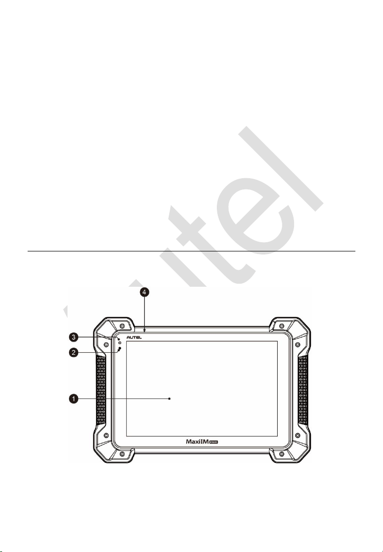
MaxiIM IM608 Display Tablet
Functional Description
1. 10.1-inch LCD Capacitive Touchscreen
Figure 2-1 Display Tablet Front View
4
2. Ambient Light Sensor – detects ambient brightness.
3. Power LED – indicates battery level & charging or system status.
4. Microphone
The power LED displays green, yellow or red depending on power level and
operating state.
A. Green
Illuminates green when the Display Tablet is charging and the
battery level is above 90%.
Illuminates green when the Display Tablet is powered on and the
battery level is above 15%.
B. Yellow
Illuminates yellow when the Display Tablet is charging and the
battery level is below 90%.
C. Red
Illuminates red when the Display Tablet is powered on and the
battery level is below 15%.
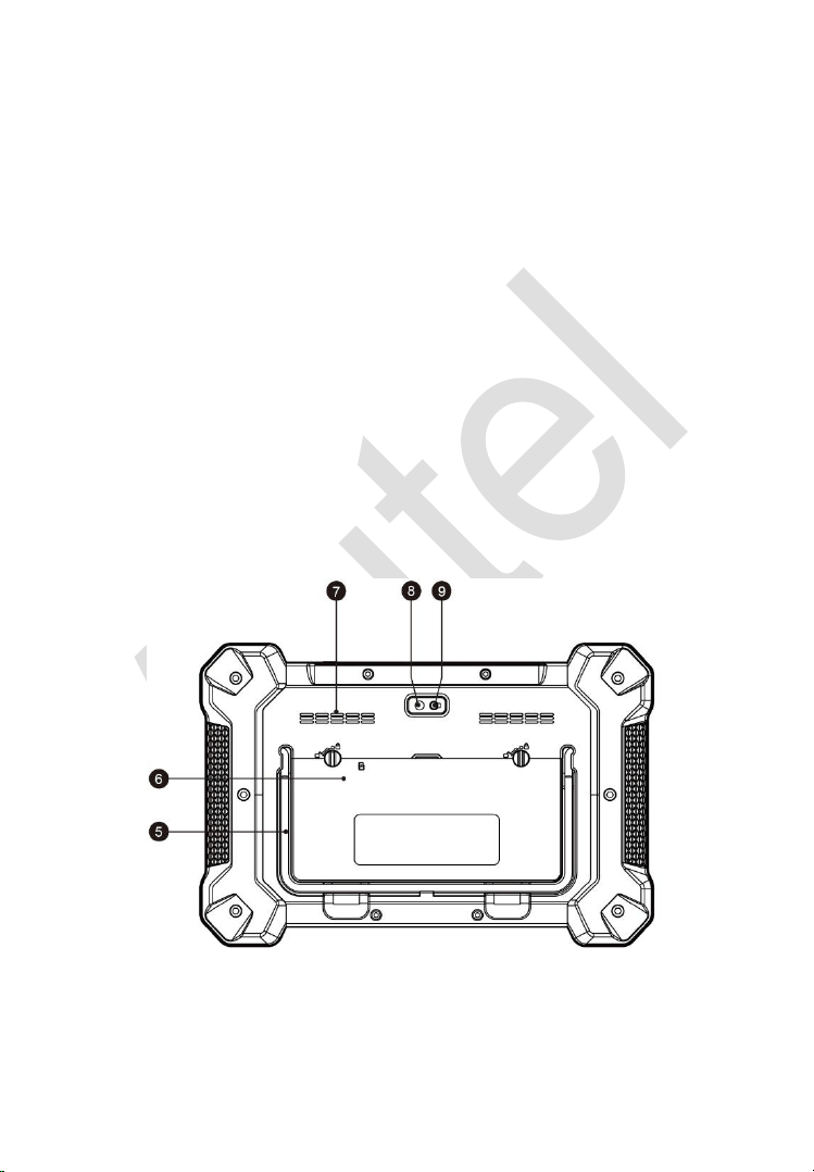
5. Collapsible Stand – extends from the back to allow hands-free viewing
of the Display Tablet.
6. Built-in Battery
Figure 2-2 Display Tablet Back View

5
7. Loudspeaker
8. Camera Lens
9. Camera Flash
10. DC Power Supply Input Port
11. Headphone Jack
12. USB Port
13. HDMI (high-definition multimedia interface) Port
14. USB Port
15. Mini USB Port
16. Lock/Power Button – turns the device on & off with long press, or locks
the screen with short press.
Power Sources
The Display Tablet can receive power from any of the following sources:
Internal Battery Pack
External Power Supply
Internal Battery Pack
The Display Tablet can be powered with the internal rechargeable battery,
which if fully charged can provide sufficient power for about 4.5 hours of
continuous operation.
Figure 2-3 Display Tablet Top View

6
External Power Supply
The Display Tablet can be powered from a wall socket using the AC/DC
power adapter. The AC/DC power supply also charges the internal battery
pack.
Technical Specifications
Table 2-1 Specifications
Item
Description
Operating System
Android
TM
4.4.2, KitKat
Processor
Samsung Exynos hexa-core Processor (1.3GHz
Quad-core ARM Cortex-A7 + 1.7GHz Dual-core
ARM Cortex-A15)
Memory
2GB RAM & 64GB On-board Memory
Display
10.1-inch LED capacitive touch screen with
1920x1200 resolution
Connectivity
Wi-Fi (802.11 a/b/g/n/ac)
USB: 2.0
BT v.2.1 + EDR
SD Card (Support up to 32GB)
HDMI
Camera (rear)
8.0 Megapixel, AF with Flashlight
Sensors
Gravity Accelerometer, Ambient Light Sensor (ALS)
Audio
Input/Output
Microphone
Dual Speakers
3-Band 3.5 mm stereo/standard headset jack
Power and Battery
15000 mAh 3.8 V lithium-polymer battery
Charging via 12 V AC/DC power supply with the
temperature between 0°C and 45°C
Input Voltage
12 V (9-24 V)

7
Item
Description
Power
Consumption
6.5 W
Operating Temp.
0 to 50°C (32 to 122°F)
Storage Temp.
-20 to 60°C (-4 to 140°F)
Dimensions (WxHxD)
300 mm (11.81”) x 220 mm (8.66”) x 50 mm (1.97”)
Weight
NW: 1.42 kg (3.13 lb.)
GW: 8.655 kg (19.08 lb.)
Protocols
ISO 9142-2, ISO 14230-2, ISO 15765-4, K/L-Line,
Flashing Code, SAE-J1850 VPW, SAE-J1850 PWM,
CAN ISO 11898, Highspeed, Middlespeed,
Lowspeed and Singlewire CAN, GM UART, UART
Echo Byte Protocol, Honda Diag-H Protocol, TP 2.0,
TP 1.6, SAE J1939, SAE J1708, Fault-Tolerant CAN
MaxiFlash – Wireless Diagnostic Interface
This multi-protocol Pass-Thru vehicle interface is a fully compliant SAE
J2534-1 & SAE J2534-2 (March 2006) device, specially designed to provide
users with convenient PC communication and ECU reprogramming
capabilities on any modern vehicle diagnostic bus, and offer the most
significant features desired by OEM customers: reliability, fast performance
and flexibility.
8
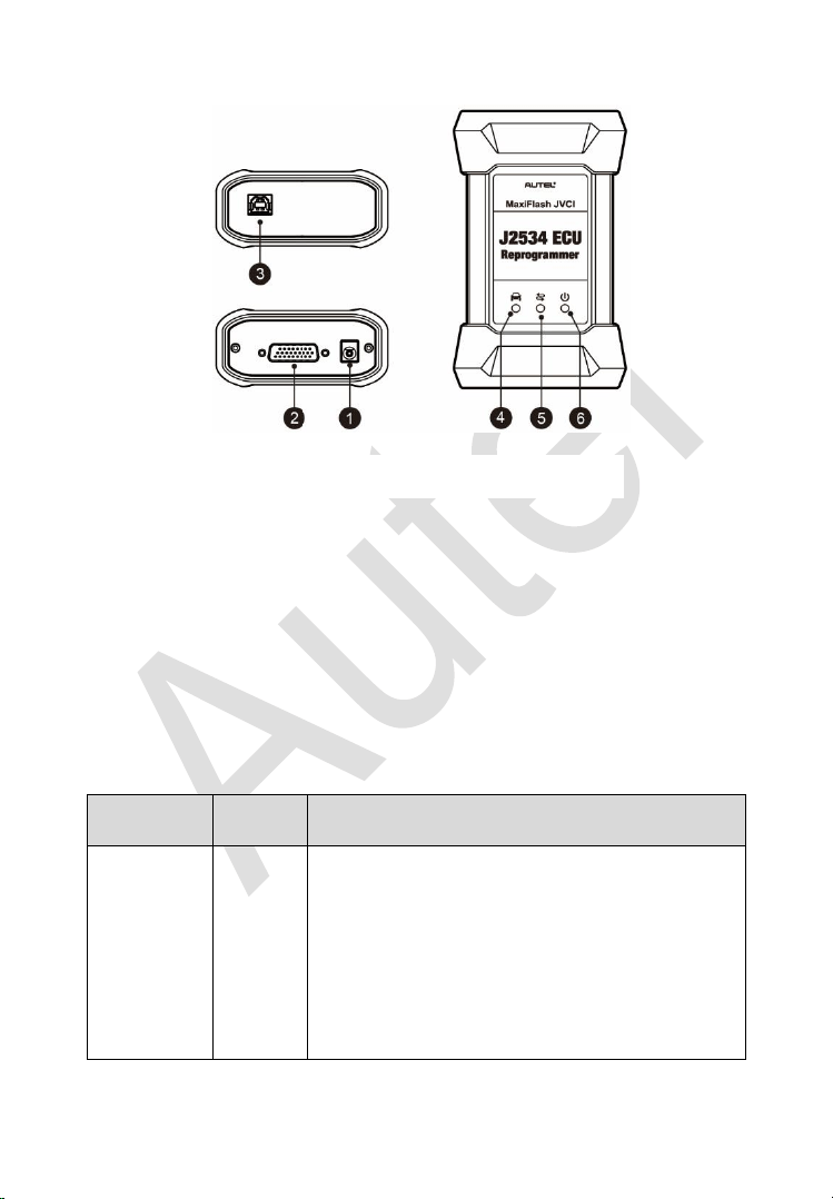
Functional Description
1. Power Port – connects the device and the power source with the adapter.
2. Vehicle Connector – connects the device to the vehicle’s DLC via a
standard high density DB-26 MVCI – OBDII cable.
3. USB Port
4. Vehicle LED
5. Connection LED
6. Power LED
Table 2-2 LED Status
LED
Color
Description
Vehicle
Green
Flashes green when communicating with the
vehicle’s system.
Note: Do not disconnect while this status LED
is on! If you interrupt the flash reprogramming
procedure while the vehicle’s ECU is blank or
only partially programmed, the module may be
unrecoverable.
Figure 2-4 MaxiFlash Views

9
LED
Color
Description
Connection
Green
Illuminates solid green when properly
connected with the display tablet via the USB
cable.
Blue
Illuminates solid blue when connected with the
display tablet via wireless (BT) connection.
Power
Green
Illuminates solid green when powered on.
Red
Flashes red when system failure occurs.
Amber
The power LED illuminates amber
automatically every time when the device is
power up, which is a normal self-test
procedure, and it will turn green automatically
later when the device starts working normally.
Technical Specifications
Table 2-3 Specifications
Name
Value
Communications
Wireless BT V2.1 + EDR,
USB 2.0
Wireless Frequency
Wireless BT V2.1+EDR, 2.4GHz
Input Voltage Range
12VDC to 24VDC
Supply Current
170mA @ 12VDC
100mA @ 24VDC
Operating Temperature
-10℃ to +50℃ (ambient)
Storage Temperature
-20℃ to +60℃ (ambient)
Dimensions (L*W*H)
149 mm * 86mm * 35 mm
10
Name
Value
Weight
0.29kg (0.64lb)
XP400 Pro
The XP400 Pro has the following functions:
(1) Read transponder data (including Mercedes Benz infrared smart key),
and generate exclusive keys.
(2) Read/write on-board EEPROM chip data, and read/write MCU/ECU chip
data.
(3) Read/write remote control transponder data and detect key frequency.
Compatible with the key Programming diagnostic tablet or a computer with
installed key Programming software, the XP400 Pro can read/write
transponder data quickly and accurately.
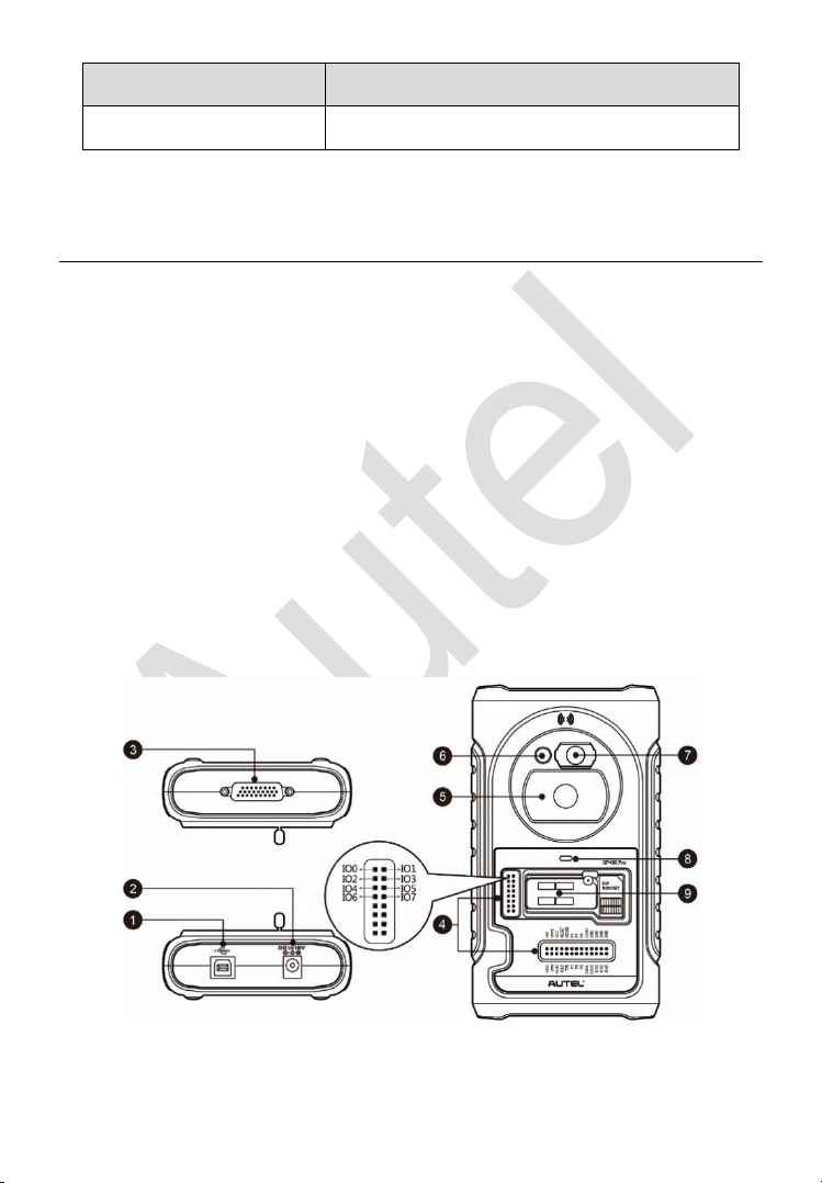
Functional Description
Figure 2-5 XP400 Pro Views

11
1. USB Port – provides data communication and 5V DC power supply.
2. DC Port – provides 12V DC power supply.
3. DB 26-Pin Port – connects with the Mercedes Benz infrared collector,
ECU cable, MCU cable and MC9S12 cable.
4. Cross Signal Pins – holds the MCU spare cable or DIY signal interface.
5. Vehicle Key Slot – holds the vehicle key.
6. Transponder Slot – holds the transponder.
7. Mercedes Infrared Key Slot – holds the Mercedes infrared key.
8. Status LED – indicates the current operating status.
9. EEPROM Component Transponder Slot – holds the EEPROM plug-in
transponder or EEPROM socket.
USB Port
The Type B USB port provides data communication and power.
DC Port
DC Port is used to provide 12V power to the XP400 Pro.
DB 26-Pin Port
Four components can be connected to this port: Mercedes Infrared Collector,
ECU Cable, MCU Cable and MC9S12 Cable.
Table 2-4 Definitions of ECU Cable
No.
Color
Definition
Note
1
Red
+12V
2
Black
GND
3
Green
IGN
4
Orange
CANL

12
No.
Color
Definition
Note
5
Blue
CANH
6
Brown
BOOTM
7
Yellow
K
8
White
LIN
Table 2-5 Definitions of MCU Cable
No.
Color
Definition
Note
1
Red and White
VPP1
2
Red and Black
VPP2
3
Red and Yellow
+12V
4
Red and Blue
VPPR
5
Black
GND
6
Green and White
S0
7
White
S1
8
Brown
S2
9
Gray
S3
10
Blue
S4
11
Red
S5
12
Orange
S6
13
Purple
S7
14
Yellow
S8
15
Green
S9

13
No.
Color
Definition
Note
16
Black
GND
Shielded
Twisted
17
White
OSC
Shielded
Twisted
Table 2-6 Definitions of MC9S12 Cable
No.
Color
Definition
Note
1
Red
+5V
2
Black
GND
3
Green
XCLKS
4
Blue
T/R
5
Yellow
RESET
6
Black
GND
Shielded
Twisted
7
White
OSC
Shielded
Twisted
Cross-shaped Signal Pin
The Cross-shaped signal pin is used to place MCU spare cable or DIY signal
cable to read or write MCU and ECU chips.
Vehicle Key Slot
Holds the vehicle key to read or write vehicle key information.
Transponder Slot
Holds the transponder to read or write transponder information.

14
Mercedes Infrared Slot
Holds Mercedes vehicle key to read or write Mercedes vehicle key
information.
Status Indicator
The Status Indicator shows the current operating status of the XP400 Pro.
Table 2-7 Description of the Status Indicator
Indicator
Status
Description
On
Light Green
Powered on and default
Flash Green
Communication
Light Red
Error
EEPROM Component Transponder Slot
Holds the EEPROM plug-in transponder or EEPROM socket to read or write
EEPROM information.
Register Coverage
Table 2-8 Register Coverage
Manufacturer
Chip Model
Note
AKM
AK93CXX
AK64XX
ALTERA
EPCSXXX
AMIC
A25LXXX
ATMEL
AT17XXXX
AT24XXXX

15
Manufacturer
Chip Model
Note
AT25XXX
AT26XXX
AT34XXX
AT45DXX
AT59CXX
AT93CXX
CATALYST/ONSEMI
CAT10XX
CAT24XXX
CAT25XXX
CAT35CXXX
CAT59CXX
CAT64LCXX
CAT93CXX
CHINGIS/PMC
PM25LDXXX
PM25LVXXX
PM25WXXX
EON
EN25BXX
EN25DXXX
EN25FXX
EN25MXX
EN25QXXX

16
Manufacturer
Chip Model
Note
EN25TXX
ESMT
F25L0XX
EXEL
XL[S]24CXX
XL[S]93CXX
XL[S]93LCXX
FAIRCHILD/NSC/RAMTRON
PM24CXXX
PM24CLXXX
PM25XXX
FM93CXX
FM93CSXX
NM24CXX
NM34XXX
NM93XX
NM93CXX
NM93CSXX
FUJITSU
MB85RCXX
GI
BAWXXXXXX
ER59XXX
GIGADEVICE
GD25QXX
GRUNDIG
GRX-XXX
HOLTEK
HT93CXX

17
Manufacturer
Chip Model
Note
ITT
NVMXXXX
MDAXXXX
KHIC
KH25LXXXX
MACRONIX
MX25LXX
MICROCHIP
24AAXX
24[F][L]CXX
25AAXXX
25LCXXX
93C/AA/LCXX[A]
93C/AA/LCXX[B]
93C/AA/LCXX[C]
MICRON
M25PXXX
M25QXXX
MITSUBISHI
M6M800X1
NEC
UPD625X
NUMONYX
M25PXXX
M25QXXX
OKI
MSM16XXX
PCT
PCT25VF032B
PHILIPS
PCA85XX
PIONEER
PDXXXX

18
Manufacturer
Chip Model
Note
ROHM
BR24CXX
BR90XX
BR93XXX
SAMSUNG
KM93CXX
KS24XXXX
SEIKO
S-24XXX
S-93XXX
SONY
CXK10XX
SPANSION
S25FLXX
S99-50084
SST
SST25LF0X0A
SST25VFXXX
ST
M24CXX
M25P[E/X]XX
M34XXX
M35XXX
M8571
M93C/SXX
M95XXX
ST24XXX
ST25XXX

19
Manufacturer
Chip Model
Note
ST93C/CSX6/X7
ST950XX
ST95P0X
WINBOND
W25PXXX
W25XXXX
XICOR
X24XXX
X504X
MCU Coverage
Table 2-9 MCU Coverage
Manufacturer
Chip Model
Note
ATMEL
ATTINYXXX
AT90XXXXX
AT90S2313
AT90S8515
AT90CAN32
AT90CAN64
AT90CAN128
ATMEGA48XX
48/48P/48PB
ATMEGA8
ATMEGA88XX
88/88P/88PB

20
Manufacturer
Chip Model
Note
ATMEGA16XX
16/162/163/164(P)/165(
P)/168(P/PB)/169(P)
ATMEGA32XX
32/323/324(P/PB)/325(
P)/328(P/PB)/329(P)/32
90(P)
ATMEGA33XX
00/00P
ATMEGA64XX
64/644(P)/645(P)/6450(
P)/649(P)/6490(P)
ATMEGA103
ATMEGA128X
128/1280/1281/1284(P)
ATMEGA256X
60/61
ATMEGA8515
ATMEGA8535
FREESCALE
MC68HC05B4
MC68HC05B6
MC68HC05B8
MC68HC05B16
MC68HC05B32
MC68HC05H12
MC68HC05L28
MC68HC05P3
MC68HC05X16

21
Manufacturer
Chip Model
Note
MC68HC05X32
MC68HC705B16
MC68HC705B16N
MC68HC705B32
MC68HC705D9
MC68HC705E6
MC68HC705E6
MC68HC705P3
MC68HC705X32
MC68HC11A1
MC68HC11A8
MC68HC11E1
MC68HC11E9
MC68HC11E20
MC68HC11E32
MC68HC11EA9
MC68HC11F1
MC68HC11K4
MC68HC11KA2
MC68HC11KA4
MC68HC11KG4

22
Manufacturer
Chip Model
Note
MC68HC11KS2
MC68HC11KW1
MC68HC11L6
MC68HC11P2
MC68HC11PA8
MC68HC11PH8
MC68HC711E9
MC68HC711E20
MC68HC711EA9
MC68HC711PH8
MC68HC08ASxxA
MC68HC08ASxxA
MC68HC908AB32
MC68HC908APxxA
MC68HC908AP64
MC68HC908AZxx
MC68HC908AZxxA
MC68HC908GP32
MC68HC908GRxx
MC68HC908GTxx
MC68HC908GZxx

23
Manufacturer
Chip Model
Note
MC68HC908JB8
MC68HC908JB16
MC68HC908JK3
MC68HC908JL3
MC68HC908JL16
MC68HC908KX2
MC68HC908LJxx
MC68HC908LKxx
MC68HC908QC4
MC68HC908QC8
MC68HC908QC16
MC68HC908QY2
MC68HC912D60
MC68HC912D60A
MC68HC912D60C
MC68HC912D60P
MC68HC912DG128
MC68HC912DG128A
MC68HC912DG128C
MC68HC912DG128P
MC68HC912DJ128A

24
Manufacturer
Chip Model
Note
MC68HC912DT128
MC68HC912DT128A
MC68HC912DT128C
MC68HC912DT128P
MC9RS08KA1
MC9RS08KA2
MC9RS08LA8
MC9S08AC8
MC9S08AC16
MC9S08AC32
MC9S08AC48
MC9S08AC60
MC9S08AC96
MC9S08AC128
MC9S08AW8
MC9S08AW16
MC9S08AW32
MC9S08AW48
MC9S08AW60
MC9S08DV16
MC9S08DV32

25
Manufacturer
Chip Model
Note
MC9S08DV48
MC9S08DV60
MC9S08DV96
MC9S08DV128
MC9S08DN16
MC9S08DN32
MC9S08DN48
MC9S08DN60
MC9S08DZ16
MC9S08DZ32
MC9S08DZ48
MC9S08DZ60
MC9S08DZ96
MC9S08DZ128
MC9S08EL16
MC9S08EL32
MC9S08FL8
MC9S08FL16
MC9S08GB32
MC9S08GB60
MC9S08GT16

26
Manufacturer
Chip Model
Note
MC9S08GT32
MC9S08GT60
MC9S08JM8
MC9S08JM16
MC9S08JM32
MC9S08JM60
MC9S08JS8
MC9S08JS16
MC9S08LC36
MC9S08LC60
MC9S08LG16
MC9S08LG32
MC9S08LH36
MC9S08LH64
MC9S08LL8
MC9S08LL16
MC9S08LL36
MC9S08LL64
MC9S08MM32
MC9S08MM32A
MC9S08MM64

27
Manufacturer
Chip Model
Note
MC9S08MP12
MC9S08MP16
MC9S08QA2
MC9S08QA4
MC9S08QB4
MC9S08QB8
MC9S08QD2
MC9S08QD4
MC9S08QE4
MC9S08QE8
MC9S08QE16
MC9S08QE32
MC9S08QE64
MC9S08QE96
MC9S08QE128
MC9S08QG4
MC9S08QG8
MC9S08RC8
MC9S08RC16
MC9S08RC32
MC9S08RC60

28
Manufacturer
Chip Model
Note
MC9S08RD8
MC9S08RD16
MC9S08RD32
MC9S08RD60
MC9S08RE8
MC9S08RE16
MC9S08RE32
MC9S08RE60
MC9S08RG32
MC9S08RG60
MC9S08SC4
MC9S08SE4
MC9S08SE8
MC9S08SF4
MC9S08SG4
MC9S08SG8
MC9S08SG16
MC9S08SG32
MC9S08SH4
MC9S08SH8
MC9S08SL8

29
Manufacturer
Chip Model
Note
MC9S08SL16
MC9S08SU8
MC9S08SU16
MC9S08SV8
MC9S08SV16
MC9S12A32
MC9S12A64
MC9S12A128
MC9S12A256
MC9S12A512
MC9S12B64
MC9S12B128
MC9S12B256
MC9S12C32
MC9S12C64
MC9S12C96
MC9S12C128
MC9S12D32
MC9S12D64
MC9S12DB128
MC9S12DG128

30
Manufacturer
Chip Model
Note
MC9S12DG256
MC9S12DJ64
MC9S12DJ128
MC9S12DJ256
MC9S12DJ512
MC9S12DP256
MC9S12DP512
MC9S12DT128
MC9S12DT256
MC9S12DT512
MC9S12GC16
MC9S12GC32
MC9S12GC64
MC9S12GC96
MC9S12GC128
MC9S12KG32
MC9S12KG64
MC9S12KG128
MC9S12KG256
MC9S12KT128
MC9S12KT256

31
Manufacturer
Chip Model
Note
MC9S12KL64
MC9S12KL128
MC9S12H128
MC9S12H256
MC9S12HN64
MC9S12HA32
MC9S12HA48
MC9S12HA64
MC9S12HY32
MC9S12HY48
MC9S12HY64
MC9S12HZ64
MC9S12HZ128
MC9S12HZ256
MC9S12P32
MC9S12P64
MC9S12P96
MC9S12P128
MC9S12XA128
MC9S12XA256
MC9S12XA512

32
Manufacturer
Chip Model
Note
MC9S12XB128
MC9S12XB256
MC9S12XD64
MC9S12XD128
MC9S12XD256
MC9S12XDG128
MC9S12XDG256
MC9S12XDG512
MC9S12XDP512
MC9S12XDQ256
MC9S12XDT256
MC9S12XDT384
MC9S12XDT512
MC9S12XEA128
MC9S12XEA256
MC9S12XEG128
MC9S12XEG256
MC9S12XEG384
MC9S12XEP768
MC9S12XEP100
MC9S12XEQ384

33
Manufacturer
Chip Model
Note
MC9S12XEQ512
MC9S12XES384
MC9S12XET256
MC9S12XET512
MC9S12XF128
MC9S12XF256
MC9S12XF384
MC9S12XF512
MC9S12XHY128
MC9S12XHY256
MC9S12XHZ256
MC9S12XHZ384
MC9S12XHZ512
MC9S12XS64
MC9S12XS128
MC9S12XS256
MPC5601D
MPC5602B
MPC5602D
MPC5603B
MPC5603C

34
Manufacturer
Chip Model
Note
MPC5604B
MPC5604C
MPC5605B
MPC5606B
MPC5607B
MPC5601P
MPC5602P
MPC5603P
MPC5604P
MPC5604E
MPC5602S
MPC5604S
MPC5606S
FUJITSU
MB90F038S
MB90F342
MB90F345
MB90F346
MB90F347
MB90F349
MB90F352
MB90F357

35
Manufacturer
Chip Model
Note
MB90F387
MB90F423
MB90F428
MB90F438L
MB90F439
MB90F455
MB90F456
MB90F457
MB90F462
MB90F497
MB90F498G
MB90F523B
MB90F543
MB90F546
MB90F548
MB90F549
MB90F553A
MB90F594A
MB90F654A
MB90F867
MB95F108AM

36
Manufacturer
Chip Model
Note
MB95F108B
MB95F116MA
MB95F118B
MB95F118M
MB95F128
MB95F128MB
MB95F136MB
MB95F156M
MB95F166
MB95F168MA
MB96F348
MB96F385
MB96F386
MB96F387
MB96F673
MB96F675
MB96F683
MB96F685
MB96F693
MB96F695
MB96F696

37
Manufacturer
Chip Model
Note
MB96F6A5
MB96F6A6
INFINEON
XC164CS-16F
XC164CS-32F
XC2060M-104F
XC2060N-40F
XC2080-96F
XC2336A-56F
XC2336A-72F
XC2361A-56F
XC2361A-72F
XC2363A-56F
XC2363A-72F
XC2364A-56F
XC2364A-72F
XC2364A-104F
XC2365A-56F
XC2365A-72F
XC2365A-104F
XC2336B-24F
XC2336B-40F

38
Manufacturer
Chip Model
Note
XC2361B-24F
XC2361B-40F
XC2363B-24F
XC2363B-40F
XC2364B-24F
XC2364B-40F
XC2365B-24F
XC2365B-40F
XC2765X-72F
XC2765X-104F
MICROCHIP
PIC12F508
PIC12F509
PIC12F510
PIC12F609
PIC12F615
PIC12F617
PIC12F629
PIC12F635
PIC12F675
PIC12F683
PIC12F752

39
Manufacturer
Chip Model
Note
PIC12(L)F1501
PIC12(L)F1552
PIC12(L)F1571
PIC12(L)F1572
PIC12(L)F1612
PIC12(L)F1822
PIC12(L)F1840
PIC12HV609
PIC12HV615
PIC16F505
PIC16F506
PIC16F54
PIC16F610
PIC16F616
PIC16F631
PIC16F636
PIC16F639
PIC16F677
PIC16F684
PIC16F685
PIC16F687

40
Manufacturer
Chip Model
Note
PIC16F688
PIC16F689
PIC16F690
PIC16F707
PIC16F72
PIC16F722
PIC16F723
PIC16F724
PIC16F726
PIC16F727
PIC16F73
PIC16F74
PIC16F76
PIC16F77
PIC16F818
PIC16F819
PIC16F83
PIC16F84
PIC16F87
PIC16F870
PIC16F871

41
Manufacturer
Chip Model
Note
PIC16F872
PIC16F873
PIC16F874
PIC16F876
PIC16F877
PIC16F88
PIC16F882
PIC16F883
PIC16F884
PIC16F886
PIC16F887
PIC16F913
PIC16F914
PIC16F916
PIC16F917
PIC16F946
PIC16F1454
PIC16F1455
PIC16F1459
PIC16(L)F707
PIC16(L)F722

42
Manufacturer
Chip Model
Note
PIC16(L)F723
PIC16(L)F724
PIC16(L)F726
PIC16(L)F727
PIC16(L)F88
PIC16(L)F1454
PIC16(L)F1455
PIC16(L)F1459
PIC16(L)F1503
PIC16(L)F1507
PIC16(L)F1508
PIC16(L)F1509
PIC16(L)F1512
PIC16(L)F1513
PIC16(L)F1516
PIC16(L)F1517
PIC16(L)F1518
PIC16(L)F1519
PIC16(L)F1526
PIC16(L)F1527
PIC16(L)F1554

43
Manufacturer
Chip Model
Note
PIC16(L)F1559
PIC16(L)F1566
PIC16(L)F1567
PIC16(L)F1613
PIC16(L)F1614
PIC16(L)F1615
PIC16(L)F1618
PIC16(L)F1619
PIC16(L)F1703
PIC16(L)F1704
PIC16(L)F1705
PIC16(L)F1707
PIC16(L)F1708
PIC16(L)F1709
PIC16(L)F1713
PIC16(L)F1716
PIC16(L)F1717
PIC16(L)F1718
PIC16(L)F1719
PIC16(L)F1823
PIC16(L)F1824

44
Manufacturer
Chip Model
Note
PIC16(L)F1825
PIC16(L)F1826
PIC16(L)F1827
PIC16(L)F1828
PIC16(L)F1829
PIC16(L)F18313
PIC16(L)F18323
PIC16(L)F18324
PIC16(L)F18325
PIC16(L)F18326
PIC16(L)F18344
PIC16(L)F18345
PIC16(L)F18346
PIC16(L)F1847
PIC16(L)F1902
PIC16(L)F1903
PIC16(L)F1904
PIC16(L)F1906
PIC16(L)F1907
PIC16(L)F1933
PIC16(L)F1934

45
Manufacturer
Chip Model
Note
PIC16(L)F1936
PIC16(L)F1937
PIC16(L)F1938
PIC16(L)F1939
PIC16(L)F1946
PIC16(L)F1947
PIC16HV610
PIC16HV616
PIC18F242
PIC18F248
PIC18F252
PIC18F258
PIC18F442
PIC18F448
PIC18F452
PIC18F458
PIC18F1220
PIC18F1230
PIC18F1320
PIC18F1330
PIC18F2220

46
Manufacturer
Chip Model
Note
PIC18F2221
PIC18F2320
PIC18F2321
PIC18F2410
PIC18F2420
PIC18F2423
PIC18F2450
PIC18F2455
PIC18F2458
PIC18F2480
PIC18F2510
PIC18F2515
PIC18F2520
PIC18F2523
PIC18F2525
PIC18F2550
PIC18F2553
PIC18F2580
PIC18F2585
PIC18F2610
PIC18F2620

47
Manufacturer
Chip Model
Note
PIC18F2680
PIC18F2682
PIC18F2685
PIC18F4220
PIC18F4221
PIC18F4320
PIC18F4321
PIC18F4410
PIC18F4420
PIC18F4423
PIC18F4450
PIC18F4455
PIC18F4458
PIC18F4480
PIC18F4510
PIC18F4515
PIC18F4520
PIC18F4523
PIC18F4525
PIC18F4550
PIC18F4553

48
Manufacturer
Chip Model
Note
PIC18F4580
PIC18F4585
PIC18F4610
PIC18F4620
PIC18F4680
PIC18F4682
PIC18F4685
PIC18F6527
PIC18F6622
PIC18F6627
PIC18F6628
PIC18F6722
PIC18F6723
PIC18F8527
PIC18F8622
PIC18F8627
PIC18F8628
PIC18F8722
PIC18F8723
PIC18F23K20
PIC18F24K20

49
Manufacturer
Chip Model
Note
PIC18F25K20
PIC18F26K20
PIC18F43K20
PIC18F44K20
PIC18F45K20
PIC18F46K20
PIC18(L)F13K22
PIC18(L)F13K50
PIC18(L)F14K22
PIC18(L)F14K50
PIC18(L)F24K50
PIC18(L)F25K50
PIC18(L)F26K50
PIC18(L)F45K50
PIC18(L)F46K50
PIC18(L)F24J10
PIC18(L)F24J11
PIC18(L)F24J50
PIC18(L)F25J10
PIC18(L)F25J11
PIC18(L)F25J50

50
Manufacturer
Chip Model
Note
PIC18(L)F26J11
PIC18(L)F26J13
PIC18(L)F26J50
PIC18(L)F26J53
PIC18(L)F27J13
PIC18(L)F27J53
PIC18(L)F44J10
PIC18(L)F44J11
PIC18(L)F44J50
PIC18(L)F45J10
PIC18(L)F45J11
PIC18(L)F45J50
PIC18(L)F46J11
PIC18(L)F46J13
PIC18(L)F46J50
PIC18(L)F46J53
PIC18(L)F47J13
PIC18(L)F47J53
PIC24F08KA101
PIC24F08KA102
PIC24F16KA101

51
Manufacturer
Chip Model
Note
PIC24F16KA102
NSC
CR16MCS9
CR16MCT9
RENESAS
R5F21112
R5F21113
R5F21114
R5F21122
R5F21123
R5F21124
R5F21244
R5F21245
R5F21246
R5F21247
R5F21248
R5F21254
R5F21255
R5F21256
R5F21257
R5F21258
R5F21262
R5F21264

52
Manufacturer
Chip Model
Note
R5F21265
R5F21266
R5F21272
R5F21274
R5F21275
R5F21276
R5F212A7
R5F212A8
R5F212AA
R5F212AC
R5F212B7
R5F212B8
R5F212BA
R5F212BC
R5F212C7
R5F212C8
R5F212CA
R5F212CC
R5F212D7
R5F212D8
R5F212DA

53
Manufacturer
Chip Model
Note
R5F212DC
R5F21354
R5F21355
R5F21356
R5F21357
R5F21358
R5F2135A
R5F2135C
R5F21546E
R5F21547E
R5F21548E
R5F2154AE
R5F2154CE
R5F21546F
R5F21547F
R5F21548F
R5F2154AF
R5F2154CF
R5F21546G
R5F21547G
R5F21548G

54
Manufacturer
Chip Model
Note
R5F2154AG
R5F2154CG
R5F21546H
R5F21547H
R5F21548H
R5F2154AH
R5F2154CH
R5F363A6
R5F363AE
R5F363AK
R5F363AM
R5F363B6
R5F363BE
R5F36406
R5F3640E
R5F3640K
R5F3640M
R5F364A6
R5F364AE
R5F364AM
R5F36506

55
Manufacturer
Chip Model
Note
R5F3650E
R5F3650K
R5F3650M
R5F3650N
R5F36CA6
R5F36CAE
R5F36CAK
R5F36CAM
R5F64110
R5F64111
R5F64112
R5F64114
R5F64115
R5F64116
R5F6411E
R5F6411F
R5F64165
R5F64166
R5F64167
R5F64168
R5F64169

56
Manufacturer
Chip Model
Note
R5F64175
R5F64176
R5F64177
R5F64178
R5F64179
R5F6417A
R5F6417B
R5F64185
R5F64186
R5F64187
R5F64188
R5F64189
R5F64206
R5F64207
R5F6420A
R5F6420B
R5F64210
R5F64211
R5F64212
R5F64213
R5F64216

57
Manufacturer
Chip Model
Note
R5F64217
R5F64218
R5F64219
R5F6421A
R5F6421B
R5F6421C
R5F6421D
R5F6421E
R5F6421F
R5F6421G
R5F6421H
R5F6442F
R5F6442H
R5F6445F
R5F6445H
R5F64116J
R5F64116K
R5F64116L
R5F64116M
R5F64117J
R5F64117K

58
Manufacturer
Chip Model
Note
R5F64117L
R5F64117M
R5F64118J
R5F64118K
R5F64118L
R5F64118M
R5F64524JFD
R5F64524LFD
R5F64524KFD
R5F64525JFD
R5F64525LFD
R5F64525KFD
R5F6452MJFD
R5F6452MLFD
R5F6452MKFD
R5F6452NJFD
R5F6452NLFD
R5F6452NKFD
M30620FC
M30624FG
M30873FH

59
Manufacturer
Chip Model
Note
M30875FH
M30876FJ
M30878FJ
M30879FK
M30879FL
M3087BFK
M3087BFL
M30880FW
M30880FH
M30880FJ
M30882FW
M30882FH
M30882FJ
R7F701002
R7F701003
R7F701006
R7F701007
R7F701008
R7F701009
R7F701010
R7F701011

60
Manufacturer
Chip Model
Note
R7F701012
R7F701013
R7F701014
R7F701015
R7F701016
R7F701017
R7F701018
R7F701019
R7F701020
R7F701021
R7F701022
R7F701023
R7F701024
R7F701025
R7F701028
R7F701029
R7F701030
R7F701032
R7F701033
R7F701034
R7F701040

61
Manufacturer
Chip Model
Note
R7F701041
R7F701042
R7F701043
R7F701044
R7F701045
R7F701046
R7F701047
R7F701048
R7F701049
R7F701050
R7F701051
R7F701052
R7F701053
R7F701054
R7F701055
R7F701056
R7F701057
R7F701A03
R7F701A23
R7F701542
R7F701543

62
Manufacturer
Chip Model
Note
R7F701546
R7F701547
R7F701557
R7F701560
R7F701561
R7F701562
R7F701563
R7F701566
R7F701567
R7F701577
R7F701580
R7F701581
R7F701582
R7F701583
R7F701586
R7F701587
R7F701597
R7F701602
R7F701603
R7F701610
R7F701611

63
Manufacturer
Chip Model
Note
R7F701612
R7F701613
R7F701620
R7F701621
R7F701622
R7F701623
uPD70F3230
uPD70F3231
uPD70F3232
uPD70F3233
uPD70F3234
uPD70F3235
uPD70F3236
uPD70F3237
uPD70F3238
uPD70F3239
uPD70F3333
uPD70F3334
uPD70F3335
uPD70F3336
uPD70F3340

64
Manufacturer
Chip Model
Note
uPD70F3341
uPD70F3342
uPD70F3343
uPD70F3344
uPD70F3345
uPD70F3346
uPD70F3347
uPD70F3348
uPD70F3349
uPD70F3350
uPD70F3351
uPD70F3352
uPD70F3353
uPD70F3354
uPD70F3355
uPD70F3356
uPD70F3357
uPD70F3358
uPD70F3364
uPD70F3365
uPD70F3366

65
Manufacturer
Chip Model
Note
uPD70F3367
uPD70F3368
uPD70F3370A
uPD70F3371
uPD70F3372
uPD70F3373
uPD70F3374
uPD70F3375
uPD70F3376A
uPD70F3377A
uPD70F3378
uPD70F3379
uPD70F3380
uPD70F3381
uPD70F3382
uPD70F3383
uPD70F3384
uPD70F3385
uPD70F3402
uPD70F3403
uPD70F3403A

66
Manufacturer
Chip Model
Note
uPD70F3421
uPD70F3422
uPD70F3423
uPD70F3424
uPD70F3425
uPD70F3426
uPD70F3427
uPD70F3433
uPD70F3438
uPD70F3451
uPD70F3452
uPD70F3453
uPD70F3454
uPD70F3461
uPD70F3464
uPD70F3465
uPD70F3466
uPD70F3469
uPD70F3470
uPD70F3471
uPD70F3472

67
Manufacturer
Chip Model
Note
uPD70F3474
uPD70F3475
uPD70F3476
uPD70F3477
uPD70F3478
uPD70F3479
uPD70F3480
uPD70F3481
uPD70F3482
uPD70F3483
uPD70F3486
uPD70F3487
uPD70F3488
uPD70F3505A
uPD70F3506
uPD70F3507
uPD70F3508
uPD70F3509
uPD70F3522
uPD70F3523
uPD70F3524

68
Manufacturer
Chip Model
Note
uPD70F3525
uPD70F3526
uPD70F3529
uPD70F3548
uPD70F3549
uPD70F3550
uPD70F3551
uPD70F3552
uPD70F3553
uPD70F3554
uPD70F3555
uPD70F3556
uPD70F3557
uPD70F3558
uPD70F3559
uPD70F3560
uPD70F3561
uPD70F3570
uPD70F3571
uPD70F3572
uPD70F3573

69
Manufacturer
Chip Model
Note
uPD70F3574
uPD70F3575
uPD70F3576
uPD70F3577
uPD70F3578
uPD70F3579
uPD70F3580
uPD70F3582
uPD70F3583
uPD70F3584
uPD70F3585
uPD70F3592
uPD70F3610
uPD70F3611
uPD70F3612
uPD70F3613
uPD70F3614
uPD70F3615
uPD70F3616
uPD70F3617
uPD70F3618

70
Manufacturer
Chip Model
Note
uPD70F3619
uPD70F3620
uPD70F3621
uPD70F3622
uPD70F3623
uPD70F3624
uPD70F3625
uPD70F3626
uPD70F3627
uPD70F3628
uPD70F3629
uPD70F3630
uPD70F3631
uPD70F3632
uPD70F3633
uPD70F3634
uPD70F3635
uPD70F3636
uPD70F3637
uPD70F3638
uPD70F3700

71
Manufacturer
Chip Model
Note
uPD70F3701
uPD70F3702
uPD70F3703
uPD70F3704
uPD70F3706
uPD70F3707
uPD70F3709
uPD70F3710
uPD70F3711
uPD70F3712
uPD70F3715
uPD70F3716
uPD70F3717
uPD70F3718
uPD70F3719
uPD70F3720
uPD70F3721
uPD70F3722
uPD70F3723
uPD70F3724
uPD70F3739

72
Manufacturer
Chip Model
Note
uPD70F3740
uPD70F3741
uPD70F3742
uPD70F3743
uPD70F3744
uPD70F3745
uPD70F3746
uPD70F3747
uPD70F3750
uPD70F3752
uPD70F3755
uPD70F3757
uPD70F3778
uPD70F3779
uPD70F3780
uPD70F3781
uPD70F3782
uPD70F3783
uPD70F3784
uPD70F3785
uPD70F3786

73
Manufacturer
Chip Model
Note
uPD70F3809
uPD70F3810
uPD70F3811
uPD70F3812
uPD70F3813
uPD70F3814
uPD70F3815
uPD70F3816
uPD70F3817
uPD70F3818
uPD70F3819
uPD70F3820
uPD70F3821
uPD70F3822
uPD70F3823
uPD70F3824
uPD70F3825
uPD70F3826
uPD70F3827
uPD70F3828
uPD70F3829

74
Manufacturer
Chip Model
Note
uPD70F3830
uPD70F3831
uPD70F3832
uPD70F3833
uPD70F3834
uPD70F3835
uPD70F3836
uPD70F3837
uPD70F3925
uPD70F3926
uPD70F3927
uPD70F3931
uPD70F3932
uPD70F3933
uPD70F3934
uPD70F3935
uPD70F3936
uPD70F3937
uPD70F3938
uPD70F3939
uPD70F4000

75
Manufacturer
Chip Model
Note
uPD70F4001
uPD70F4002
uPD70F4003
uPD70F4004
uPD70F4005
uPD70F4006
uPD70F4007
uPD70F4008
uPD70F4009
uPD70F4010
uPD70F4011
uPD70F4012
uPD70F4177
uPD70F4178
uPD70F4179
uPD70F4180
uPD76F0117
uPD76F0192
SAMSUNG
S3F9488
SILABS
C8051FXXX
SPC5607B

76
Manufacturer
Chip Model
Note
ST
SPC560BXX
SPC560CXX
SPC560DXX
SPC560PXX
SPC560APXX
ST10F2XX
STM8AF5XXX
STM8AF6XXX
STM8AL31XX
STM8AL3LXX
STM8L051XX
STM8L052XX
STM8L101XX
STM8L151XX
STM8L152XX
STM8L162XX
STM8S003XX
STM8S005XX
STM8S007XX
STM8S103XX
STM8S105XX

77
Manufacturer
Chip Model
Note
STM8S207XX
STM8S208XX
STM8S903XX
STM32F030XXX
STM32F031XXX
STM32F050XXX
STM32F051XXX
STM32F100XXX
STM32F101XXX
STM32F103XXX
STM32F205RXX
TI
MSP430F1XX2
MSP430F123
MSP430F13X
MSP430F14XX
MSP430F15XX
MSP430F16XX
MSP430F20XX
MSP430F21XX
MSP430F22XX
MSP430F23X

78
Manufacturer
Chip Model
Note
MSP430F24XX
MSP430F4XX
Technical Specifications
Table 2-10 Specifications
Item
Description
Operating Temperature
-10℃ ~ 70℃ (14℉ ~ 158℉)
Storage Temperature
-20℃ ~ 85℃ (-4℉ ~ 185℉)
Port
Type B-USB, DB26, DC12
Input Voltage
5 VDC, 12VDC
Operating Current
< 500 mA
Maximum Consumption
2.5 W
Device Dimensions (L*W*H)
168 mm * 98 mm * 30 mm
Net Weight
520 g
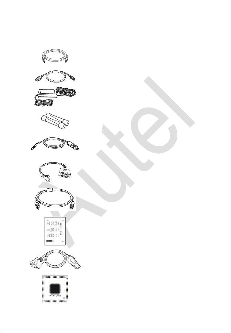
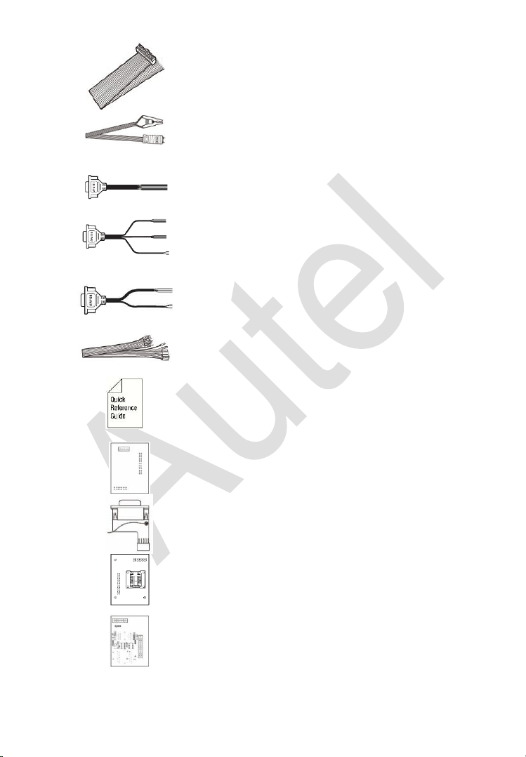
Accessories Kit
Main Cable
The Main Cable connects the MaxiFlash JVCI to the vehicle’s data link
connector (DLC). Note: Don’t use the Main Cable to connect XP400 Pro
to the vehicle’s DLC.
79
Figure 2-6 Main Cable
Other Included Accessories
USB Cable
Mini USB Cable
Connects the Display Tablet to the PC.
AC/DC Adapter (12V)
Light Fuse
6*30mm (2pcs)
Cigarette Lighter
AAC001
MED17 Cable
APC101 (USB Cable)
APB129
EEPROM Adapter
APB125
Mercedes Infrared Collector
APB103
MCU_PLCC52
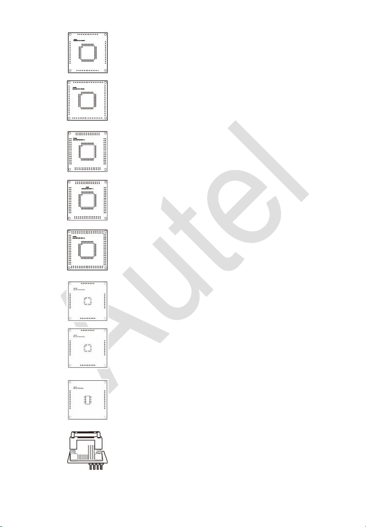
80
APB104
MCU_FQFP64
APB105
MCU_FQFP80
APB106
MCU_FQFP112
APB107
MCU_FQFP114
APB108
MCU_FQFP176
APB109
MCU_FQFP32
APB110
MCU_FQFP48
APB111
MCU_SO28
APA002
EEPROM Socket
81
APA101
Signal Cable
APA103
EEPROM Clamp
APA107
ECU Cable
APA108
MCU Cable
APA109
MC9S12 Cable
Connect Cable
Quick Guide
Device connection and software update
instructions.
APB113
PCF79XX Adapter (Optional)
APB114
EWS3 Adapter (Optional)
APB115
NEC Adapter Plate (Optional)
APB118
NEC Steering Lock Adapter (Optional)

82
APB119
TB28FXXX Adapter (Optional)
APB120
TMS370 Adapter (Optional)
APB121
AM29FXXX Adapter Plate (Optional)
APB122
AM29FXXX Adapter 1 (Optional)
APB123
AM29FXXX Adapter 2 (Optional)
APB126
M35080&D80 Adapter (Optional)
APB127
MC68HC(7)05BXX Adapter (Optional)
APB128
MC68HC05X32 Adapter (Optional)
NOTE
Optional Accessories can be purchased separately.
83
3 Getting Started
Ensure the tablet is sufficiently charged or is connected to the external
power supply (see
Power Sources on page 5).
NOTE
The images and illustrations depicted in this manual may differ from the actual
ones.
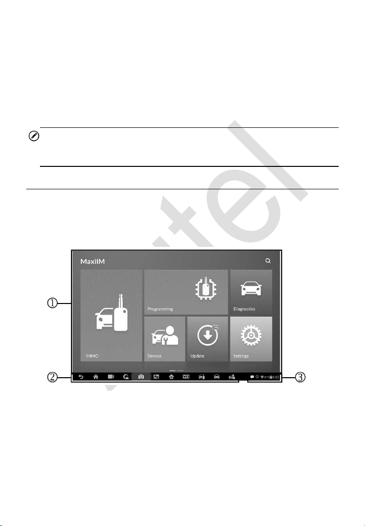
Powering Up
Long press the Lock/Power button on the top right of the tablet to power on
the unit. The power LED light will illuminate green. The system boots up, and
displays the lock screen. Slide the Lock icon to the left to enter the MaxiIM
Job Menu or slide to the right to unlock.
1. Application Buttons
2. Locator and Navigation Buttons
3. Status Icons
Figure 3-1 Sample Job Menu
84
NOTE
The tablet screen is locked by default when first powered on. It is
recommended to lock the screen to protect the information in the system and
reduce the power consumption.
The touch screen navigation is menu driven enabling quick access to
functions and features by tapping on options headings and answering dialog
windows. Detailed descriptions of the menu structures are found in the
application chapters.
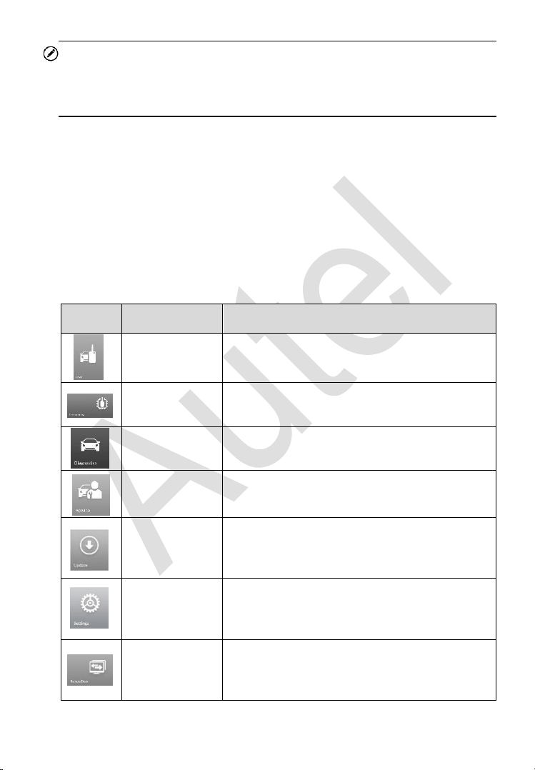
Application Buttons
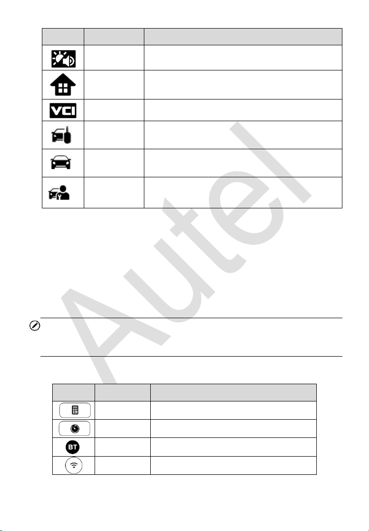
Descriptions of the tool applications are displayed in the table below.
Table 3-1 Applications
Button
Name
Description
IMMO
Accesses IMMO functions menu. See IMMO
on page 88 for details.
Programming
Accesses Programming functions menu. See
Programming on page 111 for details.
Diagnostics
Accesses diagnostic functions menu. See
Diagnostics on page 119 for details.
Service
Accesses special functions menu. See
Service
on page 139 for details.
Update
Checks for the latest update available for the
MaxiIM system, and performs updates. See
Update
on page 158 for details.
Settings
Accesses MaxiIM system settings menu and
general tablet menu. See
Settings on page
161 for details.
Remote Desk
Configures the unit to receive remote support
using the TeamViewer application program.
See Remote Desk on page 169 for details.
85
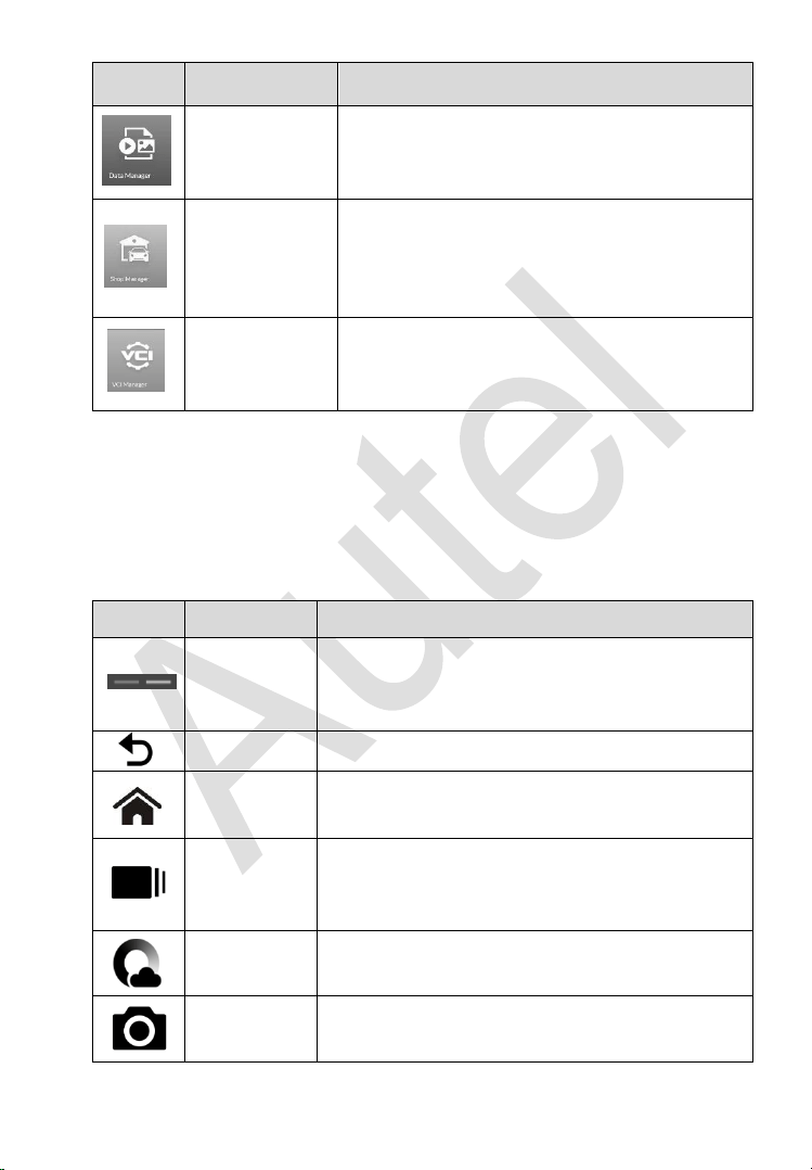
Button
Name
Description
Data Manager
Accesses the organization system for saved
data files. See
Data Manager on page 171 for
details.
Shop
Manager
Accesses Shop manager database to store
workshop, customer information and vehicle
test history. See
Shop Manager on page 176
for details.
VCI Manager
Establishes and manages BT connection with
the MaxiFlash. See
VCI Manager on page
184 for details.
Locator and Navigation Buttons
Operations of the Navigation buttons at the bottom of the screen are
described in the table below:
Table 3-2 Locator and Navigation Buttons
Button
Name
Description
Locator
Indicates the location of the screen. Swipe the
screen left or right to view the previous or next
screen.
Back
Returns to the previous screen.
Android
Home
Returns to Android System’s Home screen.
Recent
Apps
Displays a list of applications that are currently
in use. Tap an app icon to launch. To remove an
app, swipe it to the top or bottom.
Chrome
Launches the Android built-in browser.
Camera
Takes a screenshot with long press when you
want to save the displayed information.
86
Button
Name
Description
Brightness/
Volume
Adjust the brightness and volume of the tool.
MaxiIM
Home
Returns to MaxiIM Job Menu.
VCI
Returns to VCI Manager screen.
IMMO
Shortcut
Returns to the IMMO screen.
Diagnostic
Shortcut
Returns to the Diagnostic screen.
Service
Shortcut
Returns to the Service screen.
System Status Icons
As the Display Tablet is working with the Android operating system, you may
refer to Android documents for more information.
By up sliding the bottom right corner, a Shortcuts Panel will be displayed, on
which you are allowed to set various system settings of the tablet. Operations
of each button on the panel are described in the table below:
NOTE
The shortcuts buttons will be highlighted when enabled and dimmed when
disabled.
Table 3-3 Shortcuts Panel Buttons
Button
Name
Description
Calculator
Launches calculator when pressed.
Clock
Launches clock when pressed.
Bluetooth
Launches Bluetooth when pressed.
Wi-Fi
Enables/disables Wi-Fi when pressed.

87
Button
Name
Description
Airplane
Mode
Enables/disables Airplane Mode when
pressed.
System
Settings
Launches the Android System Settings
screen when pressed.
Powering Down
All vehicle communications must be terminated before shutting down the
Display Tablet. A warning message displays if you attempt to shut down the
Display Tablet when it is communicating with the vehicle. Forcing a shut-
down while communicating may lead to ECM problems on some vehicles.
Please exit the Diagnostics application before powering down.
To power down the display tablet
1. Long press the Lock/Power Button.
2. Tap Power off option.
3. Tap OK, the tablet will turn off in a few seconds.
Reboot System
In case of system crash, long press the Lock/Power button and tap Reboot
option to reboot the system.

88
4 IMMO
The IMMO application provides Smart Mode and Expert Mode to guide
technicians performing IMMO related functions, including Key Learning,
Remote Control Learning, Remote Control Add, etc.
Establish Vehicle Communication
The IMMO operations require connecting the MaxiIM IM608 tablet to the test
vehicle through the MaxiFlash using the main cable and the included USB
cable (2m). To establish proper vehicle communication to the tablet, you need
to perform the following steps:
1. Connect the MaxiFlash to the vehicle’s DLC for both communication and
power source.
2. Connect the MaxiFlash to the tablet via BT pairing, or USB connection.
3. When the above steps are completed, check the VCI navigation button
at the bottom bar on the screen, if a green check displays at the lower
right corner, the MaxiIM IM608 Pro is ready to start vehicle diagnosis.
Vehicle Connection
The method used to connect the MaxiFlash to a vehicle’s DLC depends on
the vehicle’s configuration as follows:
A vehicle equipped with an On-board Diagnostics Two (OBD II)
management system supplies both communication and 12-volt power
through a standardized J-1962 DLC.
A vehicle not equipped with an OBD II management system supplies
communication through a DLC connection, and in some cases supplies
12-volt power through the cigarette lighter receptacle or a connection to
the vehicle battery.

89
OBD II Vehicle Connection
This type of connection only requires the main cable without any additional
adapter.
To connect to an OBD II vehicle
1. Connect the main cable’s female adapter to the Vehicle Data
Connector on the MaxiFlash, and tighten the captive screws.
2. Connect the cable’s 16-pin male adapter to the vehicle’s DLC, which
is generally located under the vehicle dashboard.
NOTE
The vehicle’s DLC is not always located under the dashboard; refer to the
user manual of the test vehicle for additional connection information.
Non-OBD II Vehicle Connection
This type of connection requires both the main cable and a required OBD I
adapter for the specific vehicle being serviced.
There are three possible conditions for Non-OBD II vehicle connection:
DLC connection supplies both communication and power.
DLC connection supplies communication and power is to be supplied via
the cigarette lighter connection.
DLC connection supplies communication and power is to be supplied via
connection to the vehicle battery.
To connect to a Non-OBD II Vehicle
1. Connect the main cable’s female adapter to the Vehicle Data
Connector on the MaxiFlash, and tighten the captive screws.
2. Locate the required OBD I adapter and connect its 16-pin jack to the
main cable’s male adapter.
3. Connect the attached OBD I adapter to the vehicle’s DLC.
NOTE
Some adapters may have more than one adapter or may have test leads
instead of an adapter. Whatever the case, make the proper connection to the
vehicle’s DLC as required.

90
To connect the cigarette lighter
1. Plug the DC power connector of the cigarette lighter into the DC
power supply input port on the device.
2. Connect the male connector of the cigarette lighter into the vehicle’s
cigarette lighter receptacle.
NOTE
After the MaxiFlash is successfully connected to the vehicle, the Power LED
on the device illuminates, and a brief beep sound will be heard.
VCI Connection
After the MaxiFlash is properly connected to the vehicle, the Power LED on
the MaxiFlash illuminates solid green, and is ready to establish
communication with the tablet.
The Wireless Diagnostic Interface supports two communication methods with
the tablet: BT and USB.
Pairing Up via BT
Among all methods, BT pairing is recommended as the first choice for the
communication between the tablet and the MaxiFlash. The working range for
BT communication is about 210 feet (70 m); this means you can perform key
programming and vehicle diagnosis freely around the workshop with greater
convenience.
If you use more than one MaxiFlash to connect to the test vehicles when
customers are many, you can perform key programming and vehicle
diagnosis on various vehicles conveniently, by pairing the tablet separately
to each of the MaxiFlash connected to the different test vehicles, via BT,
without the need to repeat the plugging and unplugging procedure, which is
unavoidable through traditional wired connection, thus saves you more time
and provides more efficiency.
To pair up the tablet with the MaxiFlash via BT
1. If not already done, power up the tablet.
2. Select the VCI Manager application from the MaxiIM Job Menu.
3. When the VCI Manager application is opened, the device

91
automatically starts scanning for available VCI devices around for
BT pairing. The found devices are listed in the Setting section on the
right side of the screen.
NOTE
If no VCI device is found, this may indicate that the signal strength of the
transmitter is too weak to be detected. In this case try to get closer to the
device, or reposition the VCI device, and remove all possible objects that may
cause signal interference. When done, tap the Scan button at the top right
corner to start searching again.
4. The VCI device name displays as MaxiFlash suffixed with a serial
number. Select the required device for pairing.
5. When pairing is successfully done, the connection status displayed
to the right of the device name is shown as Paired.
6. Wait for a few seconds, and the VCI button on the system Navigation
bar at the bottom of the screen shall display a green check,
indicating the tablet is connected to the MaxiFlash, and is ready to
perform vehicle diagnosis.
Refer to
BT Pairing on page 185 for additional information.
USB Cable Connection
The USB cable connection is a simple and quick way to establish
communication between the tablet and the MaxiFlash. After properly
connecting the USB cable from the tablet to the MaxiFlash, the VCI navigation
button at the bottom bar of the screen shows a green check in a few seconds,
and the USB LED on the MaxiFlash illuminates solid green, indicating the
connection between the devices is successful.
The MaxiIM tablet is now ready to perform key programming and vehicle
diagnosis.
No Communication Message
A. If the tablet is not connected to the MaxiFlash, an “Error” message
displays. An “Error” message indicates the tablet is not communicating
with the MaxiFlash, and so cannot gain access to the vehicle control
module. In this case, you need to do the following check-ups:

92
Check if the MaxiFlash is powered on.
In case of wireless connection, check if the network is configured
correctly, or if the right device has been paired.
If during the diagnosis process, communication is suddenly
interrupted due to the loss of signal, check if there are any objects
that causes signal interruption.
Check if the MaxiFlash is properly positioned. It is recommended to
put the MaxiFlash with the front side up.
Try standing closer to the MaxiFlash to obtain more stable signals,
and faster communication speed. In case of wired connection, check
the cable connection between the tablet and the MaxiFlash.
Check if the green LED on the MaxiFlash is illuminated for BT or
USB.
Check if the Error LED on the MaxiFlash is on, this may indicate
there is a communication error between the devices, in this case try
re-establishing the connection again; if this does not work, there may
be a hardware problem with the device, in this case contact Autel or
local distributor for technical support.
B. If the MaxiFlash is unable to establish a communication link, a prompt
message displays with check instructions. The following conditions are
the possible causes for this massage to display:
The MaxiFlash is unable to establish a communication link with the
vehicle.
You’ve selected a system for testing that the vehicle is not equipped
with.
There is a loose connection.
There is a blown vehicle fuse.
There is a wiring fault on the vehicle, or the data cable or adapter.
There is a circuit fault in the data cable or adapter.
Incorrect vehicle identification was entered.
93
Getting Started
Ensure a communication link is established between the test vehicle and the
tablet via the main cable, and the XP400 Pro is connected to the tablet with
the supplied USB cable.
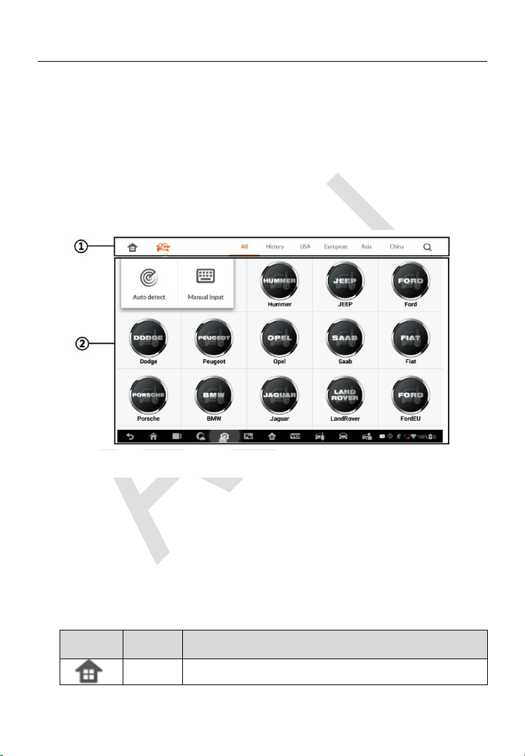
Vehicle Menu Layout
When the tablet is properly connected to the vehicle, the platform is ready to
start vehicle diagnosis. Tap on the IMMO application button on the MaxiIM
IM608 Pro Job Menu to access the Vehicle Menu.
1. Top Toolbar Buttons
2. Manufacturer Buttons
Top Toolbar Buttons
The operations of the toolbar buttons at the top of the screen are listed and
described in the table below:
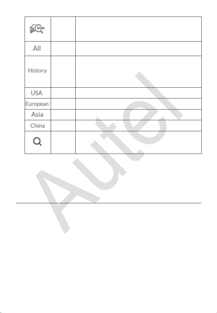
Table 4-1 Top Toolbar Buttons
Button
Name
Description
Home
Returns to the MaxiIM Job Menu.
Figure 4-1 Sample Vehicle Menu
94
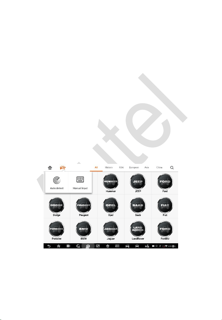
VIN
Scan
Displays a dropdown list; tap Auto Detect for auto
VIN detection; tap Manual Input to enter VIN
manually.
All
Displays all the vehicle makes in the vehicle menu.
History
Displays the stored test vehicle history records. This
option provides you direct access to the previously
tested vehicle recorded during previous test
sessions. See Vehicle History on page 177.
USA
Displays the USA vehicle menu.
Europe
Displays the European vehicle menu.
Asia
Displays the Asian vehicle menu.
China
Displays the Chinese vehicle menu.
Search
Displays the virtual keyboard to manually enter the
specific vehicle make required.
Manufacturer Buttons
To begin, select the manufacturer button of the test vehicle, followed by the
vehicle model and year.
Vehicle Identification
The MaxiIM diagnostic system supports four methods for Vehicle
Identification.
1. Auto VIN Scan
2. Manual VIN Input
3. Automatic Selection
4. Manual Selection
Auto VIN Scan and Manual VIN Input functions are applicable for IMMO,
Diagnostic and Service applications, Automatic Selection and Manual
Selection are applicable for Diagnostic and Service applications. In IMMO,
95
except Auto VIN Scan and Manual VIN Input methods, technicians can also
manually select vehicle manufacturer, instrument information step by step to
locate the desired IMMO part, but it is a little different from Automatic
Selection and Manual Selection. Besides, as Programming does not require
connection with the vehicle, therefore, Auto VIN Scan is not applicable for
this application, and technicians can manually select the part information
follow the onscreen instructions to display the function menu.
Auto VIN Scan
The MaxiIM diagnostic system features the latest VIN-based Auto VIN Scan
function to identify vehicles and it is applied to IMMO, Programming,
Diagnostic and Service applications. IMMO provides two modes: Smart Mode
and Expert Mode, and only Smart Mode can be accessed by using Auto VIN
function.
To perform Auto VIN Scan
1. Tap the IMMO application button from the MaxiIM Job Menu. The
Vehicle Menu displays.
2. Tap the VIN Scan button on the top toolbar to open a dropdown list.
3. Select Auto Detect. Once the test vehicle is successfully identified,
the screen will display the vehicle profile. Tap OK at the bottom right
Figure 4-2 Sample Auto VIN Screen
96
to confirm the vehicle profile. If the VIN does not match with the test
vehicle’s VIN, enter VIN manually or tap Read to acquire VIN again.
4. Tap Yes to confirm the vehicle profile or NO if the information is not
correct.
5. The tool establishes communication with the vehicle and reads the
IMMO control unit information.
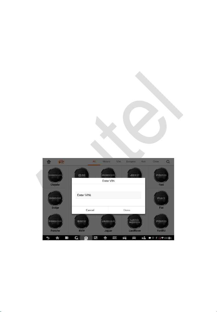
Manual VIN Input
For vehicles that not supporting the Auto VIN Scan function, you may
manually enter the vehicle VIN.
To perform Manual VIN Input
1. Tap the IMMO application button from the MaxiIM Job Menu. The
Vehicle Menu displays.
2. Tap the VIN Scan button on the top toolbar.
3. Select Manual Input.
4. Tap the input box and enter the correct VIN.
Figure 4-3 Sample Enter VIN Screen
5. Tap Done to complete or tap Cancel to exit Manual Input.

97
Automatic Selection
The Auto VIN Scan can be selected after selecting the test vehicle
manufacturer.
To perform Automatic Selection
1. Tap the Diagnostic application button from the MaxiIM Job Menu.
The Vehicle Menu displays.
2. Tap the manufacturer button of the test vehicle.
3. Tap Automatic Selection and the VIN information will be
automatically acquired. Follow the on-screen instruction to display
the function screen.
Manual Selection
When the vehicle’s VIN is not automatically retrievable through the vehicle's
ECU, or the specific VIN is unknown, the vehicle can be manually selected.
This mode of vehicle selection is menu driven, repeat the first two steps from
the automatic selection operation and tap Manual Selection. Through a
series of on-screen prompts and selections, the test vehicle is chosen. If
needed, press the ESC button at the bottom right corner of the screen to
return to the previous screen.
Navigation
Navigating the IMMO interface and selecting test are discussed in this section.
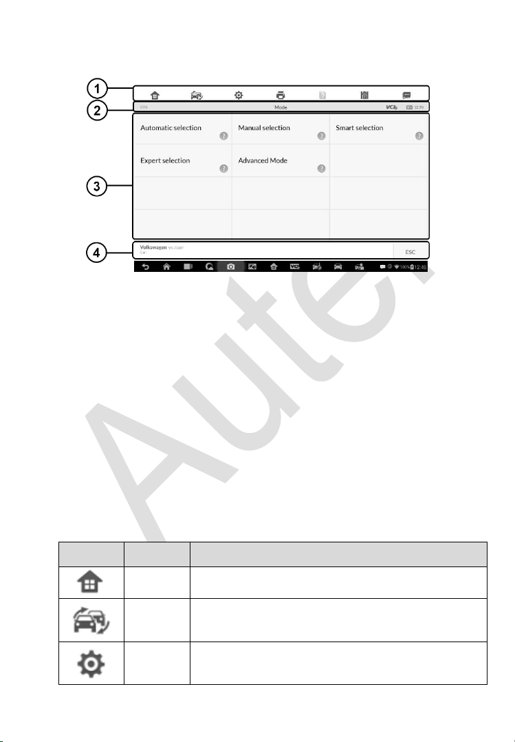
98
IMMO Screen Layout
Figure 4-4 Sample Mode Selection Screen
The IMMO screens typically include four sections.
1. Operation Toolbar
2. Status Information Bar
3. Main Section
4. Functional Buttons
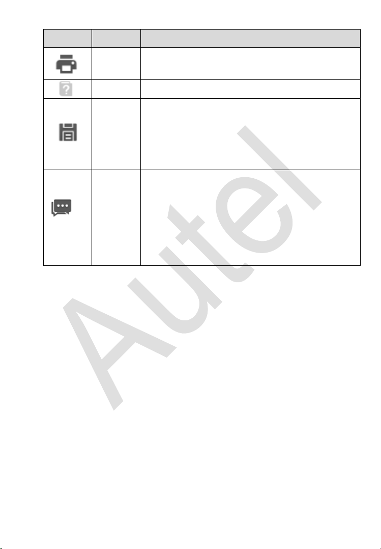
Operation Toolbar
The Operation Toolbar contains a number of buttons such as print and save.
The table below provides a brief description of the operations.
Table 4-2 Operation Toolbar Buttons
Button
Name
Description
Home
Returns to the MaxiIM Job Menu.
Vehicle
Swap
Exits the function session of the currently identified
test vehicle and returns to the vehicle menu screen.
Settings
Opens the settings screen. See Settings on page
161.
99
Button
Name
Description
Print
Prints a copy of the displayed data. See Printing
Setting for additional information on page 163.
Help
Displays operational instructions or tips.
Save
Tap this button to open a sub menu, tap Save This
Page to take a screenshot.
All saved data is stored in the Data Manager
application for later reviews. See
Data Manager
Operations on page 171.
Data
Logging
Records the communication data and ECU
information of the test vehicle. The saved data can
be reported and sent to the technical center via the
Internet.
You can go to the Support application to follow up
the processing progress, see
Data Logging on page
175 for detailed information.
To print data
1. Tap the IMMO application button from the MaxiIM Job Menu. The
Print button on the toolbar is available throughout the IMMO
operations.
2. Tap Print. A drop-down menu displays. Tap Print This Page to print
a screenshot of the current screen.
3. A temporary file will be created and send to the connected computer
for printing.
4. When the file is transferred successfully, a confirmation message
displays.
To submit Data Logging reports
1. Tap the IMMO application button from the MaxiIM Job Menu. The
Data Logging button on the toolbar is available throughout the
IMMO operations.

100
2. Tap the Data Logging button. The button displays blue during the
active recording process.
3. Tap the Data Logging button again to end recording. A submission
form will display for inputting of report information.
4. Tap the Send button to submit the report form via the Internet. A
confirmation message displays when the report has been
successfully sent.
Status Information Bar
The Status Information Bar at the top of the Main Section displays the
following items:
1. Menu Title – displays the menu heading of the Main Section.
2. Voltage Icon – displays the vehicle’s voltage status.
Main Section
The Main Section of the screen varies depending on the stage of operations.
The Main Section can display vehicle identification selections, the main menu,
test data, messages, instructions and other information. In this case, it shows
the two modes IMMO provides: Smart Mode and Expert Mode.
Functional Buttons
The displayed Functional Buttons vary depending on the stage of operations.
Functional buttons can be used to navigate menus, to save or clear data, to
exit scanning and to perform a number of other control functions. The use of
these buttons will be discussed in detail in the following sections of the
corresponding test operations.
Screen Messages
Screen messages appear when additional input is needed before proceeding.
There are three main types of on-screen messages: Confirmation, Warning,
and Error.

101
Confirmation Messages
This type of messages usually displays as an “Information” screen to inform
the user that a selected action cannot be reversed or when an action has
been initiated and confirmation is needed to continue.
When a user-response is not required to continue, the message displays
briefly.
Warning Messages
This type of messages displays a warning that a selected action may result
in an irreversible change or loss of data. An example of this type of message
is the “Erase Codes” message.
Error Messages
Error messages display when a system or procedural error has occurred.
Examples of possible errors include a disconnection or communication
interruption.
Making Selections
The IMMO application is a menu driven program that presents a series of
choices. As a selection is made, the next menu in the series displays. Each
selection narrows the focus and leads to the desired test. Tap the screen to
make menu selections.
IMMO
The IMMO application requires a data link to the IMMO electronic control
system of the test vehicle for diagnosis via OBD II connection. The application
retrieves vehicle IMMO information and performs IMMO related functions,
including Key Learning, Remote Control Learning, Remote Control Add, etc.
There are two options available when accessing the IMMO section:
1. Smart Mode – accesses to a function menu where each function is
configured as a smart guide system.
2. Expert Mode – accesses to a function menu where each function is
separated from each other.
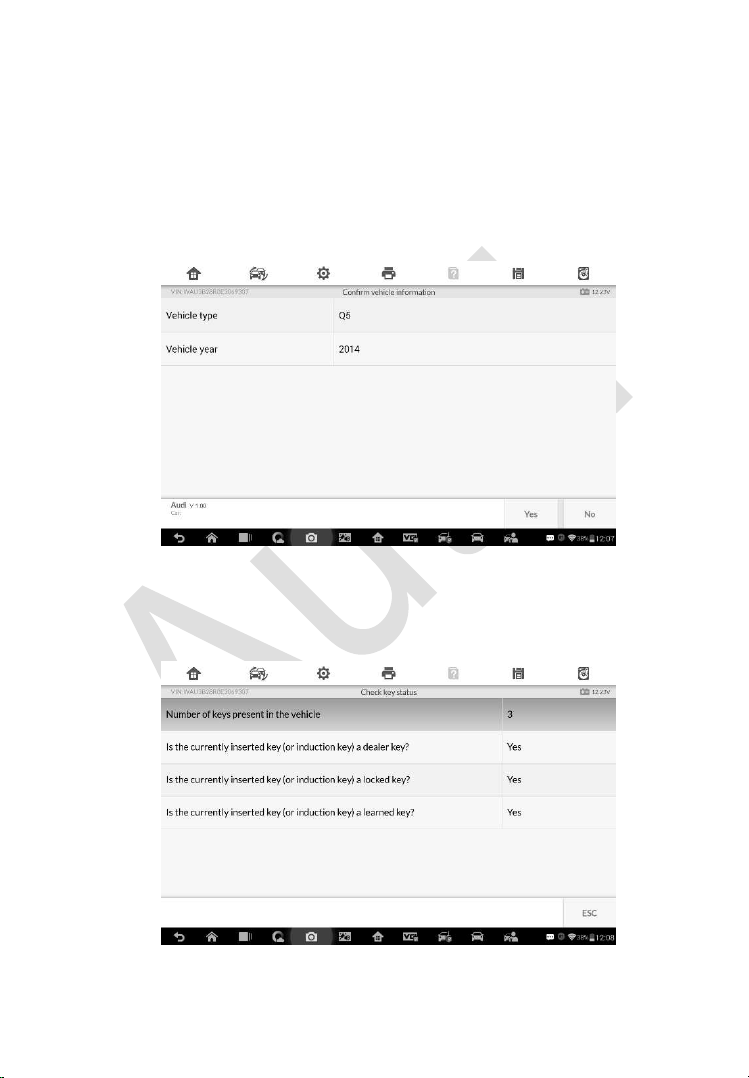
102
After a mode is selected and the tablet establishes communication with the
vehicle, the corresponding function menu or selection menu displays.
Smart Mode
The Smart Mode provides guided functions with step-by-step instructions.
Once the test vehicle is identified, a vehicle profile will display, select Yes to
continue.
Figure 4-5 Sample Vehicle Information Screen
The tablet will access the vehicle IMMO ECU to read IMMO related
information. Press OK to continue. Then the vehicle key status will display.
Figure 4-6 Sample Check Key Status Screen
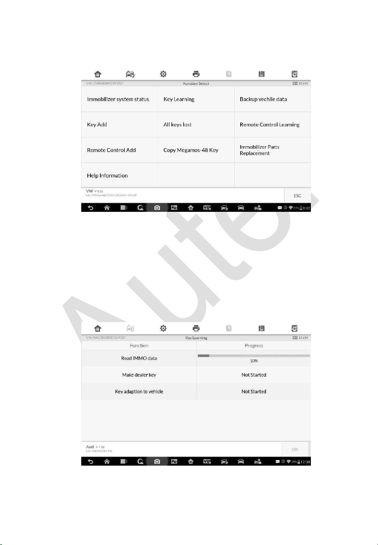
103
Read the vehicle key status carefully and press OK to display the function
menu.
Figure 4-7 Sample Function Menu in Smart Mode
The functions vary by IMMO parts, please follow the onscreen instructions to
select the correct IMMO part.
Take Key Learning as an example.
1. Select Key Learning from the function menu. The tablet will
automatically start to read IMMO data.
Figure 4-8 Sample Key Learning Screen 1
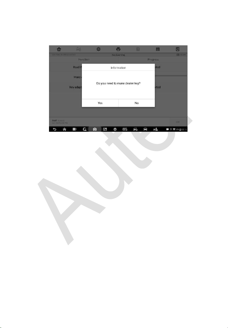
104
2. When Read IMMO data completes, the tablet will prompt a “Do you need
to make dealer key?” message, select Yes to confirm, or select NO to
quit the operation.
Figure 4-9 Sample Key Learning Screen 2
3. Follow the onscreen instruction to place a Blank Key in the XP400 Pro
key slot and press OK to continue.
4. If the new key is blocked, the tablet will ask if you want to unlock the key,
select Yes to continue, or select NO to quit the operation.
5. A “Make dealer key success!” message displays when the process is
completed successfully.
6. Then the tablet will automatically move to the next step, Key adaption to
vehicle, and the following message will prompt up.
7. Make selections according to the test vehicle.
8. Input the numbers of the keys to be learned and press OK to continue.
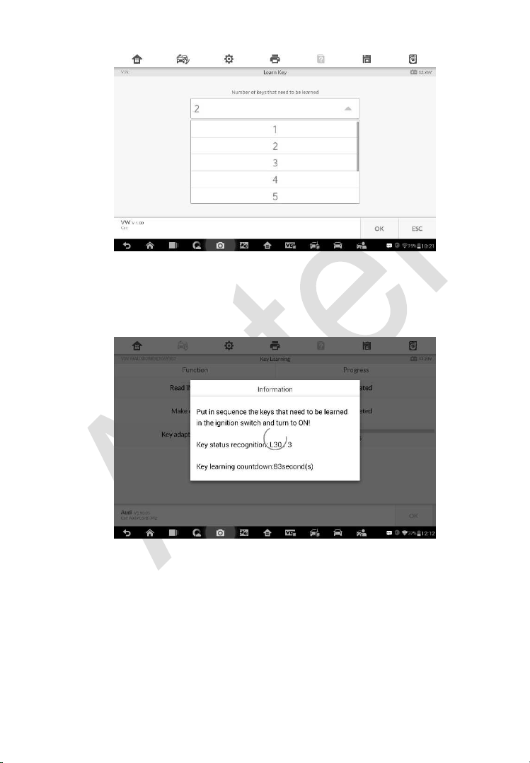
105
Figure 4-10 Sample Key Learning Screen 3
9. Follow the onscreen instructions to insert the key to be learned into the
vehicle ignition switch.
Figure 4-11 Sample Key Learning Screen 4
10. When Key Learning is completed successfully, the following screen
displays. Press OK to exit the function.
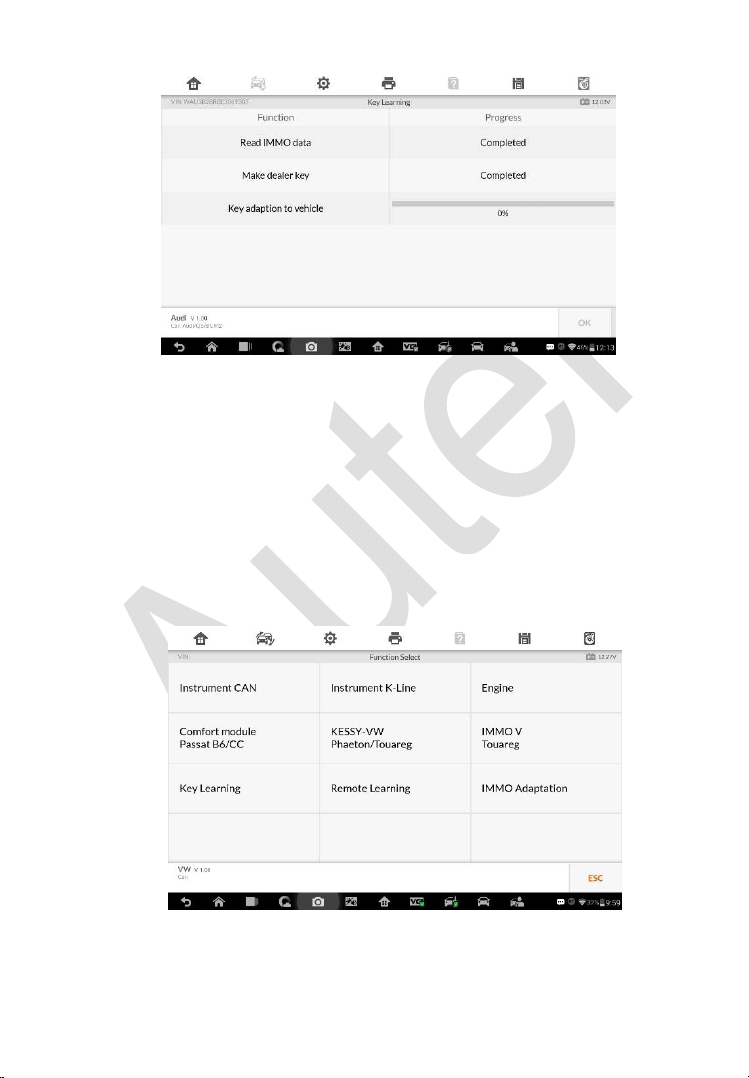
106
Figure 4-12 Sample Key Learning Screen 5
Expert Mode
Expert Mode provides skilled technicians a convenient way to perform
individual IMMO functions they need. All the function options in this mode are
separated segments. If needed, technicians can only perform one segment
function instead of a whole process provided in Smart Mode.
1. Select Expert Mode from the mode selection screen. The screen
displays individual IMMO functions for selection.
Figure 4-13 Sample Expert Mode Function Menu
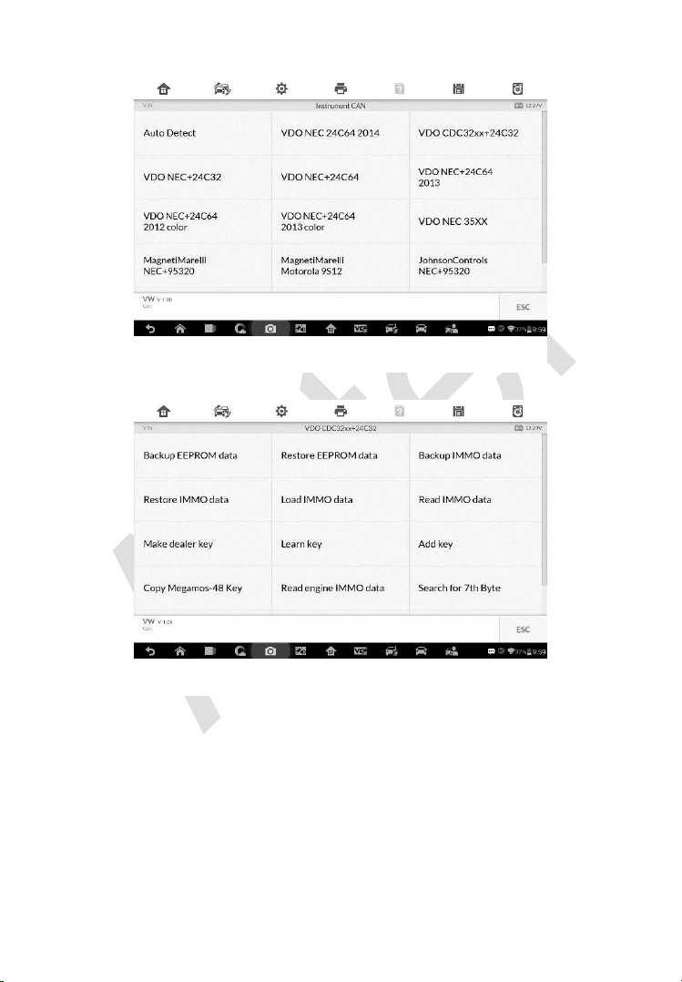
107
2. For Instrument CAN and Engine, the tool supports auto detect.
3. Tap Auto Detect and the screen displays the functions menu.
Read IMMO Data
Select Read IMMO Data from the function menu. The tablet will start to read
IMMO information. Review the data and press OK to exit.
Figure 4-14 Sample Auto Detect Screen
Figure 4-15 Sample Function Screen
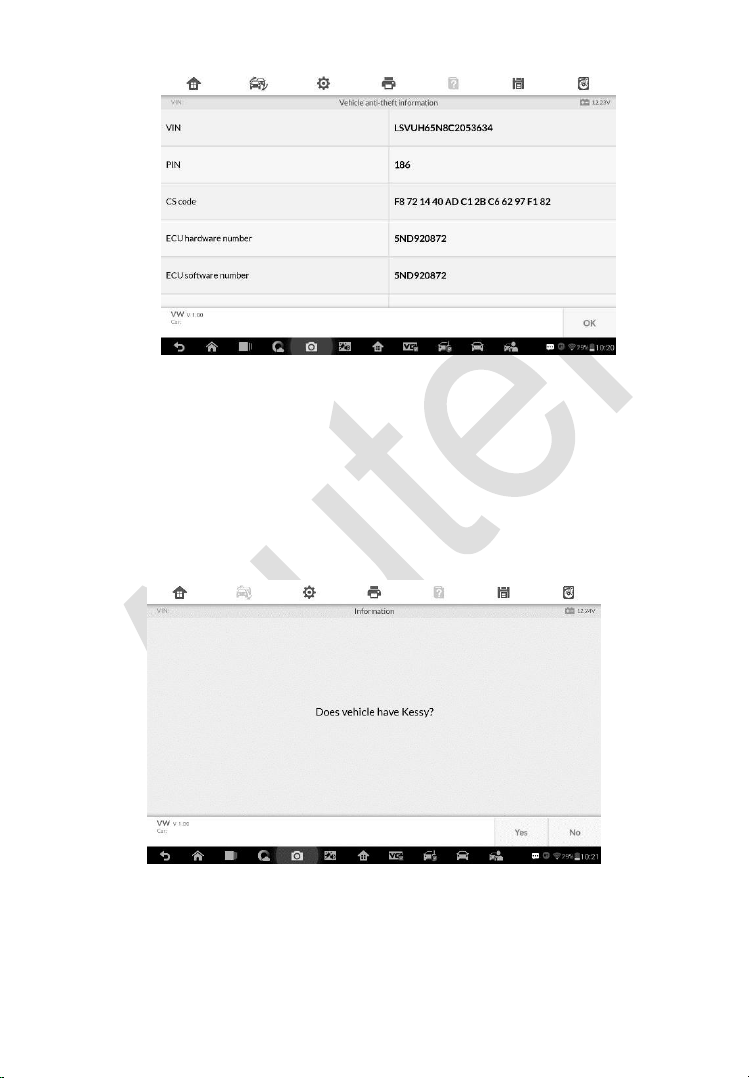
108
Figure 4-16 Sample Read IMMO Data Screen
After the IMMO data is read, technicians can perform other IMMO functions
with the read data in Expert Mode.
Learn Key
1. Select Learn Key from the function menu. The tool will confirm whether
the vehicle has Kessy, tap Yes or No according to the situation to
continue.
2. Enter the number of keys to be learned.
Figure 4-17 Sample Kessy Confirm Screen
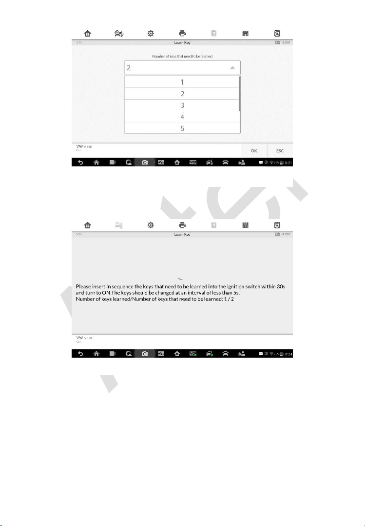
109
3. Insert in sequence the keys that need to be learned into the vehicle. The
keys should be changed at an interval of less than 5s.
4. Once the keys are successfully learned, the screen displays the
message “Key learning completed”, tap OK to exit.
Figure 4-19 Sample Learn Key Screen 2
Figure 4-18 Sample Learn Key Screen 1

110
Figure 4-20 Sample Learn Key Screen 3
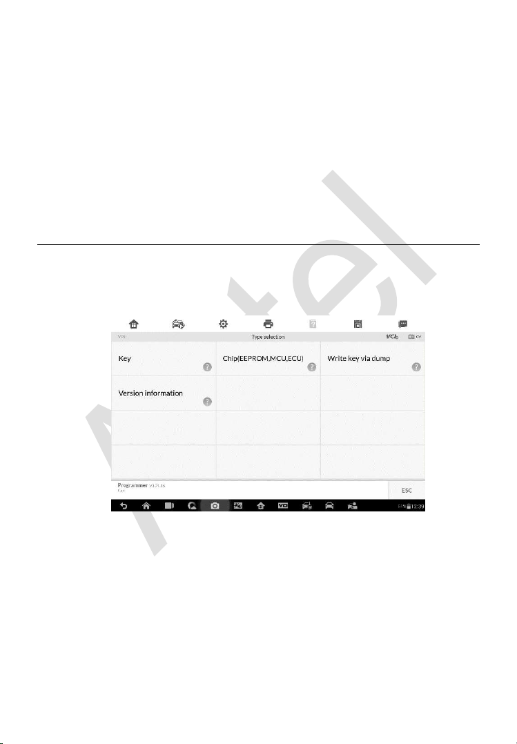
111
5 Programming
The Programming application requires connection between the tablet and the
XP400 Pro, and no vehicle connection is required. This application can
access the key chip, read, retrieve and write key information, as well as other
key related functions.
Programming
Select the vehicle manufacturer in the vehicle menu, and then follow the
onscreen instructions to select the instrument information to display the
function menu.
Figure 5-1 Sample Programming Function Menu
Chip Read & Write
1. Select Chip Read & Write from the menu.
2. Select the chip type if needed. In this example, select EEPROM.
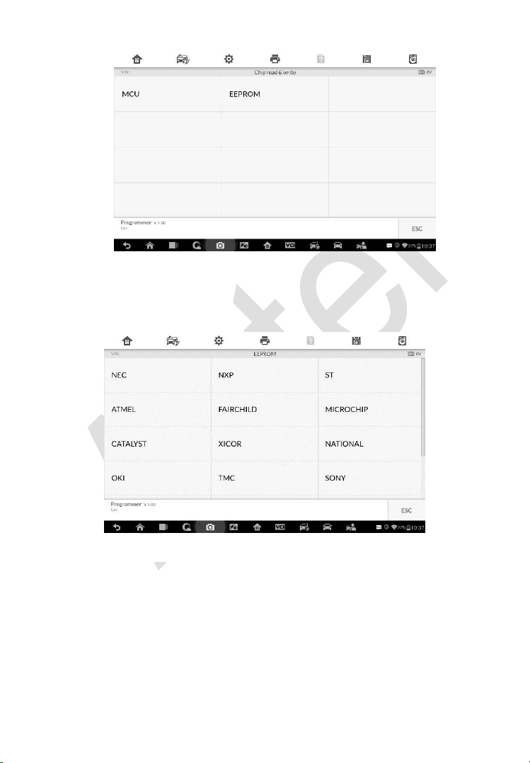
112
Figure 5-2 Sample Select Chip Type Screen
3. The screen displays the types of EEPROM supported. Select the right
type.
4. Select Read Operation on the next menu.
Figure 5-3 Sample Chip Type Screen
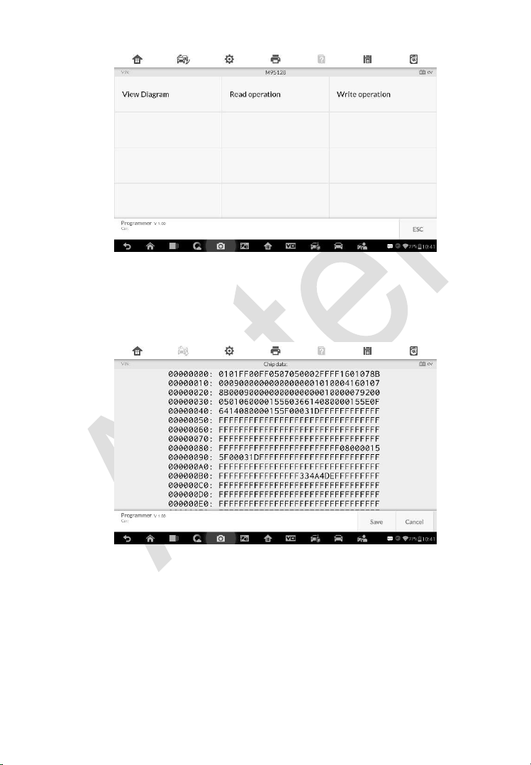
113
Figure 5-4 Sample Operations Menu
5. The chip data screen displays. Select Save to save the data, or select
Cancel to exit.
Figure 5-5 Sample Read Operation Screen
6. Type the file name and select Confirm, the chip data will be saved on the
tablet. And a “File saved successfully.” message displays.
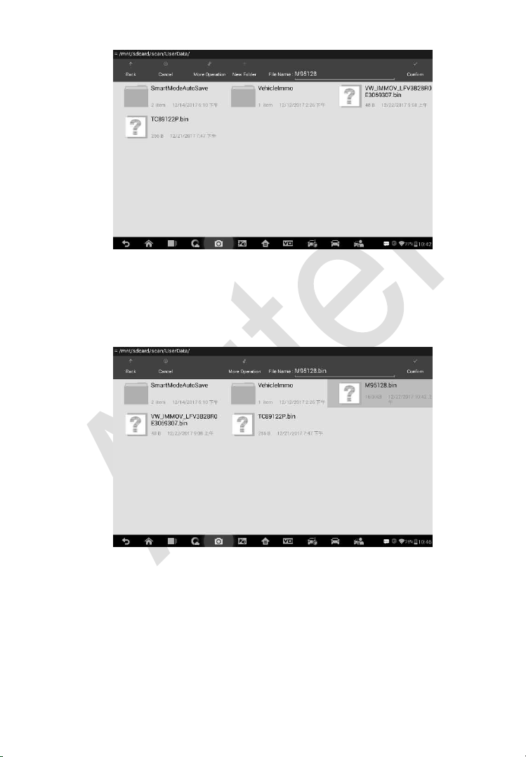
114
Figure 5-6 Sample Save Data Screen
7. Select Write Operation from the operations menu. The tablet will open
the default folder, select the saved data and click Confirm to write it into
a black chip. And a “Chip written successfully.” message displays.
Figure 5-7 Sample Write Operation Screen
Key Read & Write
1. Select Key Read & Write from the menu.
2. Select the key type or automatic detection. Please note that automatic
detection does not support detection of IR key.
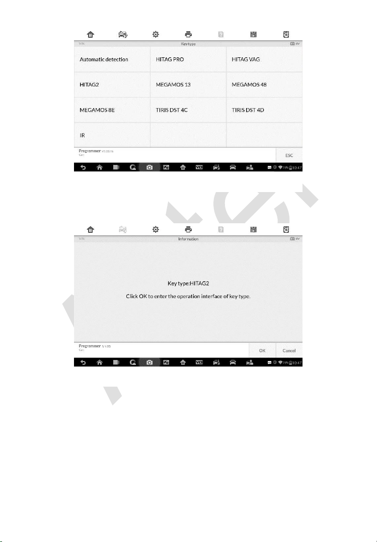
115
3. Once the key type is successfully detected, the screen displays the key
type, tap OK to enter the operation interface.
4. The screen displays the supported functions which usually include
Read out key ID, Read out key information, Write page.
Figure 5-9 Sample Key Type Screen
Figure 5-8 Sample Key Select Screen
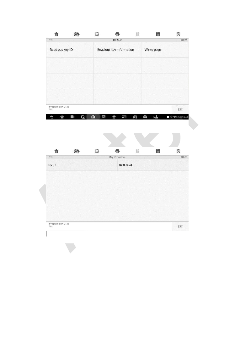
116
5. Tap Read out key ID to read the key ID.
6. Tap Read out key information to read the information.
Figure 5-10 Sample Functions Screen
Figure 5-11 Sample Key ID Screen
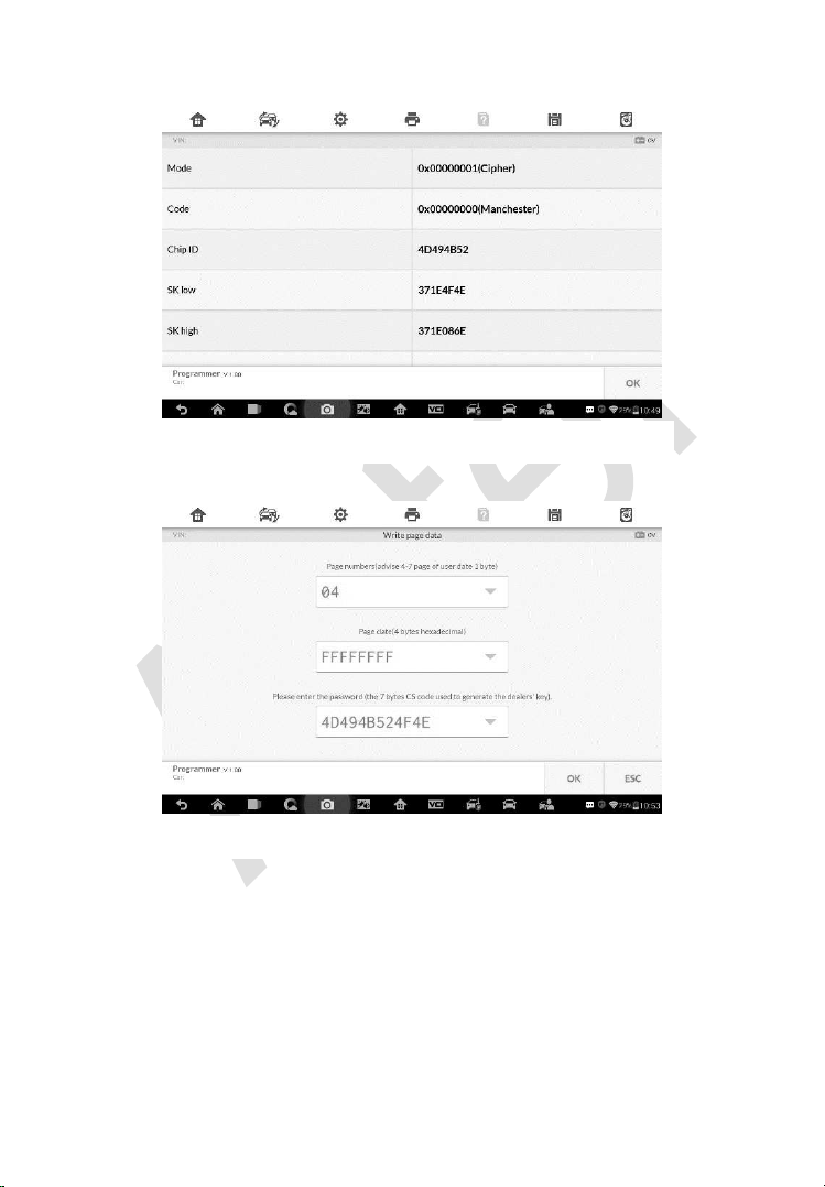
117
7. Tap Write page data to write the data.
Remote Detection
1. Tap Remote Detection from the menu, the function menu displays.
Figure 5-13 Sample Write Page Data Screen
Figure 5-12 Sample Read Out Key Information Screen
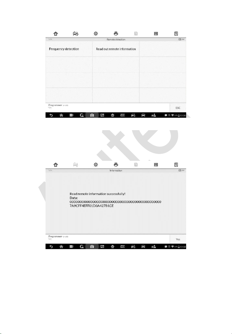
118
2. Put the key into suitable area and press down any key button. The
screen displays the frequency of the key.
3. Tap Read out remote information to check the information.
Figure 5-85 Sample Frequency Display Screen
Figure 5-15 Sample Remote Information Screen
Figure 5-14 Sample Remote Detection Function Screen

119
6 Diagnostics
The Diagnostics application can retrieve ECU information, read & erase
DTCs, and view live data. The Diagnostics application can access the
electronic control unit (ECU) for various vehicle control systems, including
engine, transmission, antilock brake system (ABS), airbag system (SRS).
Diagnosis
The Diagnostics application enables a data link to the electronic control
system of the test vehicle for vehicle diagnosis via OBD II connection. The
application performs functional tests, retrieves vehicle diagnostic information
such as trouble and event codes and live data for various vehicle control
systems, such as engine, transmission, and ABS.
There are two options available when accessing the Diagnosis section:
1. Auto Scan – starts auto scanning for all the available systems on the
vehicle.
2. Control Units – displays a selection menu of all available control units of
the test vehicle.
After a section is made and the tablet establishes communication with the
vehicle, the corresponding function menu or selection menu displays.
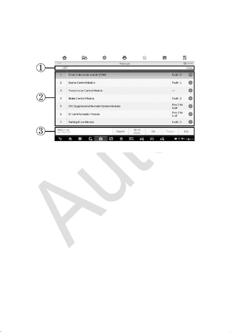
120
Auto Scan
The Auto Scan function performs a comprehensive scanning over all the
ECUs in the vehicle to locate systems’ faults and retrieve DTCs. The sample
operation interface of Auto Scan displays as below:
1. Navigation Bar
2. Main Section
3. Functional Buttons
Navigation Bar
List Tab – displays the scanned data in list format.
Progress Percentage – indicates the test progress.
Main Section
Column 1 – displays the sequence numbers.
Column 2 – displays the scanned systems.
Column 3 – displays the diagnostic indicators describing test results.
These indicators are defined as follows:
Fault(s) | #: Fault(s) indicates there is/are detected fault code(s) present;
“#” indicates the number of the detected faults.
Pass | No Fault: Indicates the system has passed the scanning process
and no fault has been detected.
Figure 6-1 Sample Auto Scan Operation Screen

121
Column 4 – to perform further diagnosis or testing on a specific system item,
tap the button to the right of that item. A Function Menu screen
will display.
Functional Buttons
A brief description of the operations of the Auto Scan’s Functional Buttons’
are displayed in the table below.
Table 6-1 Functional Buttons in Auto Scan
Name
Description
Report
Displays the diagnostic data in the report form.
Quick
Erase
Deletes codes. A warning message screen will display to
inform you of possible data loss when this function is
selected.
OK
Confirms the test result. Continues to the system
diagnosis after the required system is selected by
tapping the item in the Main Section.
Pause
Suspends scanning and it will change to Continue
button after tapping.
ESC
Returns to the previous screen or exits Auto Scan.
Control Units
Manually locate a required control system for testing through a series of
selection choices. Follow the menu driven procedures and make proper
selection; the application guides the user to the proper diagnostic function
menu based on selections.
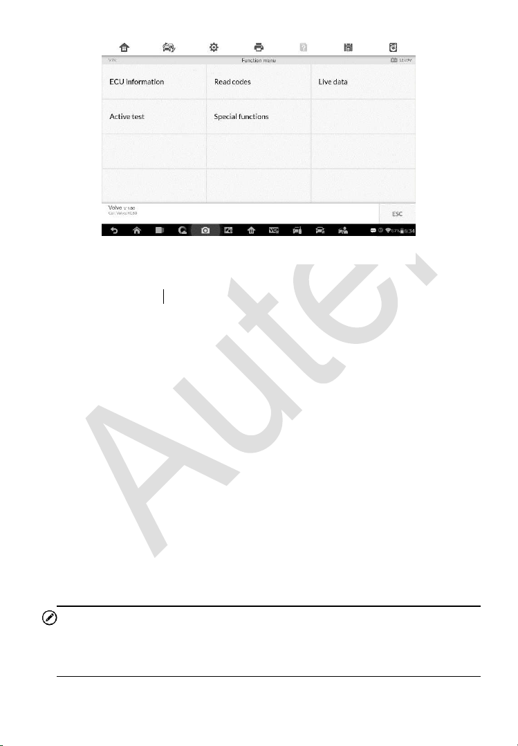
122
The Function Menu options vary slightly for different vehicles. The function
menu may include:
ECU Information – provides the retrieved ECU information in detail. An
information screen opens upon selection.
Read Codes – displays detailed information of DTC records retrieved
from the test vehicle’s ECU.
Erase Codes – erases DTC records and other data from the test
vehicle’s ECU.
Live Data – retrieves and displays live data and parameters from the test
vehicle’s ECU.
Active Test – provides specific subsystem and component tests. This
selection may appear as Actuators, Actuator Test, or Function Tests and
the tests options vary by vehicle manufacturer and model.
Special Functions – provides component adaptation or variant coding
functions for custom configurations, and also allows you to reprogram
adaptive values for certain components after making repairs. Depending
on the test vehicle, this selection may sometimes appear as Control Unit
Adaptations, Variant Coding, Configuration or something similar.
NOTE
Toolbar functions such as saving and printing of test results can be performed
throughout diagnostic testing. Data logging and access to help information
are also available.
Figure 6-2 Sample Function Menu Screen
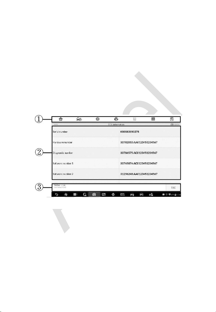
123
To perform a diagnostic function
1. Establish communication with the test vehicle.
2. Identify the test vehicle by selecting from the menu options.
3. Select the Diagnosis section.
4. Locate the required system for testing by Auto Scan or through
menu driven selections in Control Units.
5. Select the desired diagnostic function from the Function Menu.
ECU Information
This function retrieves and displays the specific information for the tested
control unit, including unit type, version numbers and other specifications.
The sample ECU Information screen displays as below:
1. Diagnostics Toolbar Buttons – see Table 4-2 Operation Toolbar Buttons
on page 98 for detailed descriptions of the operations for each button.
2. Main Section – the left column displays the item names; the right column
shows the specifications or descriptions.
3. Functional Button – ESC (or Back) button is available; tap it to exit after
viewing.
Figure 6-3 Sample ECU Information Screen
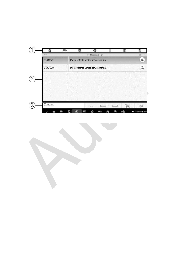
124
Read Codes
This function retrieves and displays the DTCs from the vehicle’s control
system. The Read Codes screen varies for each vehicle being tested. On
some vehicles, freeze frame data can also be retrieved for viewing. The
sample Read Codes screen displays as below:
1. Diagnostics Toolbar Buttons – see
Table 4-2 Operation Toolbar Buttons
on page 98 for detailed descriptions of the operations for each button.
2. Main Section
Code Column – displays the retrieved codes from the vehicle.
Status Column – indicates the status of the retrieved codes.
Description Column – detailed descriptions for the retrieved codes.
Snowflake Icon – only displays when freeze frame data is available
for viewing; selecting this icon will display a data screen, which looks
and behaves similar to the Read Codes screen.
3. Functional Button
Help – tap to view fault code information, including fault description,
condition for fault identification, and driver information.
Freeze frame – tap to view the freeze frame data.
Search – tap to search related fault code information on Google.
Clear DTC – tap to clear the diagnostic trouble code.
ESC – tap to return to the previous screen or exit the function.
Figure 6-4 Sample Read Codes Screen

125
Erase Codes
After reading the retrieved codes from the vehicle and certain repairs have
been carried out, you can decide to erase the codes from the vehicle using
this function. Before performing this function, make sure the vehicle’s ignition
key is in the ON (RUN) position with the engine off.
To erase codes
1. Tap Erase Codes from the Function Menu.
2. A warning message displays to advice of data loss if this function is
completed.
a) Tap Yes to continue. A confirming screen displays when the
operation is successfully done.
b) Tap No to exit.
3. Tap ESC on the confirming screen to exit Erase Codes.
4. Perform the Read Codes function again to check if codes have been
erased successfully.
Live Data
When this function is selected, the screen displays the data list for the
selected module. The items available for any control module vary from one
vehicle to another. The parameters display in the order that they are
transmitted by the ECM, so expect variation between vehicles.
Gesture scrolling allows for quick movement through the data list. Use one or
two fingers to swipe the screen up or down to locate the data you want. The
figure below shows a typical Live Data screen:
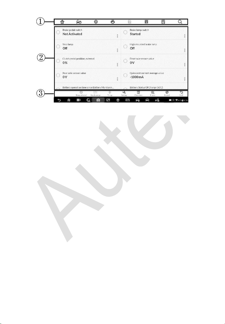
126
1. Diagnostics Toolbar Buttons – taps the drop-down button at the top
center of the screen and the toolbar buttons will display. See Table 4-2
Operation Toolbar Buttons on page 98 for detailed descriptions of the
operations for each button.
2. Main Section
Name Column – displays the parameter names.
a) Check Box – tap the check box on the left side of the parameter
name to make item selection. Tap the check box again to
deselect the item.
b) Drop-down Button – tap the drop-down button on the right side
of the parameter name to open a sub menu, providing data
display mode options.
Value Column – displays the values of the parameter items.
Unit Column – displays the unit for the parameters.
To change the unit mode, tap the Setting button on the top
toolbar and select a required mode. See
Unit on page 161 for
more information.
3. Display Mode
There are four types of display modes available for data viewing. Select
the proper mode for the diagnostic purpose.
Figure 6-5 Sample Live Data Screen

127
Tap the drop-down button on the right side of the parameter name to
open a sub menu. There are four buttons to configure the data display
mode, and a Help button for access to additional information.
Each parameter item displays the selected mode independently.
1) Analog Gauge Mode – displays the parameters in form of an analog
meter graph.
2) Text Mode – this is the default mode which displays the parameters
in texts and shows in list format.
NOTE
Status parameters, such as a switch reading, can primarily be viewed in text
form such as ON, OFF, ACTIVE, and ABORT. Whereas, value parameters,
such as a sensor reading, can be displayed in text mode and additional graph
modes.
3) Waveform Graph Mode – displays the parameters in waveform
graphs.
When this mode is selected, three control buttons display on the right
side of the parameter item for manipulation of display status.
Text Button – resumes Text Display Mode.
Scale Button – changes the scale values that are displayed below
the waveform graph. There are four scales available: x1, x2, x4 and
x8.
Zoom-in Button – tap once to display the selected data graph in full
screen.
Edit Button – tap this button to open an edit window, on which
you can set the waveform color and the line thickness displayed
for the selected parameter item.
Scale Button - changes the scale values, which are displayed
below the waveform graph. There are four scales available: x1,
x2, x4 and x8.
Zoom-out Button – exits full screen display.
4) Digital Gauge Mode – displays the parameters in form of a digital
gauge graph.
Full Screen Display – this option is only available in the waveform graph
mode, and primarily used in Graph Merge status for data comparison.

128
Under this mode, there are three control buttons available on the top right
side of the screen.
To edit the waveform color and line thickness in a data graph
1. Select 1 to 3 parameter items to display in Waveform Graph
mode.
2. Tap the Zoom-in Button on the right to display the data graph
in full screen.
3. Tap the Edit Button, an edit window appears.
4. Select a parameter item on the left column.
5. Select a desired sample color from the middle column.
6. Select a desired sample line thickness from the right column.
7. Repeat step 3-5 to edit the waveform for each parameter item.
8. Tap Done to save the setting and exit, or tap Cancel to exit
without saving.
4. Functional Buttons
The operations of available functional buttons on Live Data screen are
described below:
Back – returns to previous screen or exits the function.
Record – starts recording the retrieved live data; the recorded data is
then stored as a video clip in the Data Manager application for future
reviews. This function can be triggered automatically at preset threshold
value or values may be set manually. The triggering mode and record
duration can be configured in the Setting mode of Live Data.
Freeze frame – displays the retrieved data in freeze frame mode.
Previous Frame – displays previous frame if the freeze frame data.
Next Frame – advances to the next frame in the freeze frame data.
Clear Data – clears all previously retrieved parameter values at a
particular cutting point.
To Top – moves a selected data item to the top of the list.
Graph Merge – taps this button to merge selected data graphs (for
Waveform Graph Mode only). This function is useful for comparisons
between different parameters.
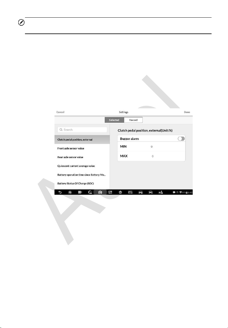
129
NOTE
In this mode, Graph Merge can only display up to three parameter items.
To cancel Graph Merge mode, tap the drop-down button on the right side
of the parameter name, and select a data display mode.
Show – taps this option to switch between the two options; one displays
the selected parameter items, the other displays all the available items.
Setting – taps this button to access setting screen to set the trigger mode,
recording duration and threshold values for data recording, and define
other control settings.
Figure 6-6 Sample Setting Mode in Live Data
There are four navigation buttons on top of the Setting mode screen.
Selected Button – displays the configuration screen on which you can
set the threshold values, an upper limit and a lower limit, for triggering
the buzzer alarm
. This function is only applied to the Waveform Graph
display mode.
a) MIN – taps to open a virtual keyboard, allowing you to enter the
required lower limit value.
b) MAX – taps to open a virtual keyboard, allowing you to enter the
required upper limit value.
c) Buzzer Alarm – switches the alarm on and off.

130
To set threshold limits for the parameter values
1. Tap the Setting functional button at the bottom of the Live Data
screen.
2. Tap the Selected navigation button.
3. Select a parameter item on the left column, or enter the item name
in the Search bar.
4. Tap on the right side of the MIN button, and enter the required
minimum value.
5. Tap on the right side of the MAX button, and enter the required
maximum value.
6. Tap the ON/OFF button on the right side of the Buzzer Alarm button
to turn it on or off.
7. Tap Done to save the setting and return to the Live Data screen; or
tap Cancel to exit without saving.
If the threshold limits are successfully set, two horizontal lines will appear on
each of the data graphs (when Waveform Graph Mode is applied) to indicate
the alarming point. The threshold lines are shown in different colors from the
waveform of the parameters for distinction.
Record Button – displays the configuration screen for Record Setting,
on which you can set the trigger type, duration and trigger point for the
data recording function.
a) Trigger Type – sets the trigger mode for data recording, mainly of
two kinds: Manual and Auto. There are four options available:
1) Manual – allows you to manually start and stop data recording
2) DTC – auto triggers data recording when any DTC is detected
3) DTC Check Mode – auto triggers data recording when certain
pre-selected DTC types are detected
4) Parameter – auto triggers data recording when any parameter
value reaches the preset threshold
b) Duration – sets the recording time (for Auto trigger mode only)
c) Trigger Point – reserves a relative percentage of a record length
before the data recording start point for reference (for Auto trigger
mode only)

131
To perform setting for live data record
1. Tap the Setting functional button at the bottom of the Live Data
screen.
2. Tap the Record navigation button.
3. Tap the button on the right of Trigger Type bar and select the
required trigger mode.
4. Tap the button on the right of Duration bar and select a length
of time.
5. Tap the button on the right of Trigger Point bar and select a
relative percentage of a record length to be reserved before the data
recording start point.
6. Tap Done to save the setting and return to the Live Data screen; or
tap Cancel to cancel without saving and exit Setting.
Done Button – confirms and saves the setting, and returns to the Live
Data screen.
Cancel Button – cancels the setting operation, and returns to the Live
Data screen.
Active Test
The Active Test function is used to access vehicle-specific subsystem and
component tests. Available test vary by vehicle manufacturer, year, and
model, and only the available tests display in the menu.
During an active test, the tester outputs commands to the ECU in order to
drive the actuators. This test determines the integrity of the system or parts
by reading the engine ECU data, or by monitoring the operation of the
actuators, such as switching a solenoid, relay, or switch, between two
operating states.
Selecting Active Test opens a menu of test options that varies by vehicle
make and model. Selecting a menu option activates the test. Follow all screen
instructions while performing tests. How and what information is presented
on the screen varies according to the type of test being performed. Some
toggle and variable control tests display Active Test Controls at the top of the
screen with data stream information below, or vice versa.
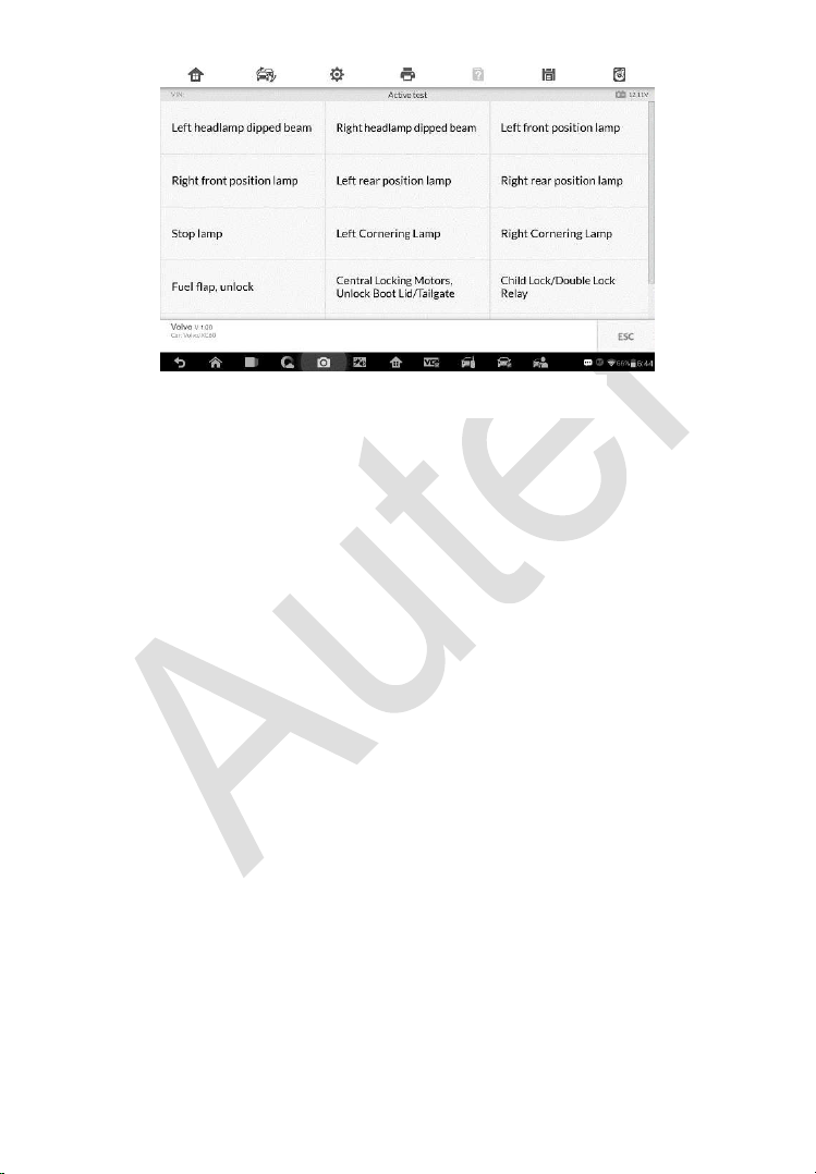
132
The functional buttons at the lower right corner of the Active Test screen
manipulate the test signals. The operational instructions are displayed on the
main section of the test screen. Simply follow the on-screen instructions and
make appropriate selections to complete the tests. Each time when an
operation is successfully executed, message such as “Command Finished”,
“Activation Successful”, or something similar displays.
Tap the ESC functional button to exit the test when finished.
Special Functions
These functions perform various component adaptations, allowing you to
recalibrate or configure certain components after making repairs or
replacement.
The main section of the Adaptation Operation screen displays a list of
operational and vehicle status information, which mainly consists of four parts:
1. The first part in the top line shows the description of the operation being
performed, and the execution status is displayed on the right, such as
Completed, or Activated.
2. The second part shows the preconditions or requirements for executing
the operation being selected.
3. The third part displays the current conditions of the vehicle control
module being learned for comparison to the preconditions suggested by
the second part. If the current condition of the control module is out of
Figure 6-7 Sample Active Test Screen
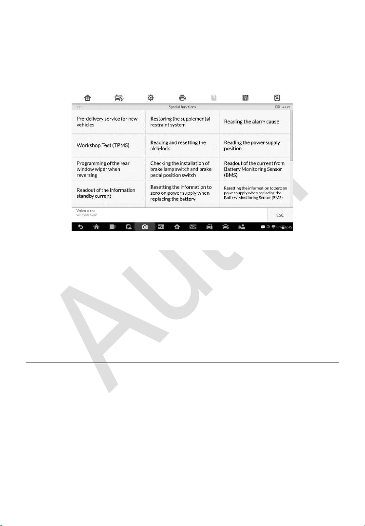
133
the suggested limit value, you must adjust the vehicle condition to meet
the requirement.
4. The last part displays the instruction of how to use the functional button
at the lower right corner of the screen to manipulate the teach-in
operations.
Read the information carefully and check the vehicle condition accordingly,
when you are sure that the vehicle is ready to perform the adaptation, simply
follow the instructions provided to make appropriate selections. When the
operation is done, an execution status message such as Completed, Finished
or Successful, displays.
Tap the ESC button to exit the function.
Generic OBD II Operations
A fast-access option for OBD II/EOBD vehicle diagnosis is available on the
Vehicle Menu screen. This option presents a quick way to check for DTCs,
isolate the cause of an illuminated malfunction indicator lamp (MIL), check
monitor status prior to emissions certification testing, verify repairs, and
perform a number of other services that are emissions-related. The OBD
direct access option is also used for testing OBD II/EOBD compliant vehicles
that are not included in the Diagnostics database.
Figure 6-8 Sample Special Functions Screen

134
Functions of the diagnostics toolbar buttons at the top of the screen are the
same as those available for specific vehicle diagnostics. See Table 4-2
Operation Toolbar Buttons
on page 98 for details.
General Procedure
To access the OBD II/EOBD diagnostics functions
1. Tap the Diagnostics application button from the MaxiIM Job Menu.
The Vehicle Menu displays.
2. Tap the EOBD button. There are two options to establish
communication with the vehicle.
Auto Scan – when this option is selected the diagnostic tool
attempts to establish communication using each protocol in
order to determine which one the vehicle is broadcasting on.
Protocol – when this option is selected the screen opens a
submenu of various protocols. A communication protocol is a
standardized way of data communication between an ECM and
a diagnostic tool. Global OBD may use several different
communication protocols.
3. Select a specific protocol under the Protocol option. Wait for the
OBD II Diagnostic Menu to appear.
NOTE
Tapping the button displayed beside the function name opens a bubble
with additional function information.
4. Select a function option to continue.
DTC & FFD
I/M Readiness
Live Data
On-Board Monitor
Component Test
Vehicle Information
Vehicle Status
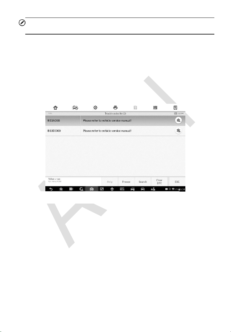
135
NOTE
Some functions are supported only on certain vehicle makes.
Function Descriptions
This section describes the various functions of each diagnostic option:
DTC & FFD
When this function is selected, the screen displays a list of Stored Codes and
Pending Codes. When the Freeze Frame data of certain DTCs are available
for viewing, a snowflake button will display on the right side of the DTC item.
The erase codes function can be applied by tapping the Clear DTC button at
the bottom of the screen.
Stored Codes
Stored codes are the current emission related DTCs from the ECM of the
vehicle. OBD II/EOBD Codes have a priority according to their emission
severity, with higher priority codes overwriting lower priority codes. The
priority of the code determines the illumination of the MIL and the codes
erase procedure. Manufacturers rank codes differently, so expect to see
differences between makes.
Pending Codes
These are codes whose setting conditions were met during the last drive
Figure 6-9 Sample DTC & FFD Screen

136
cycle, but need to be met on two or more consecutive drive cycles before
the DTC actually sets. The intended use of this service is to assist the
service technician after a vehicle repair and after clearing diagnostic
information, by reporting test results after a driving cycle.
a) If a test failed during the driving cycle, the DTC associated with that
test is reported. If the pending fault does not occur again within 40
to 80 warm-up cycles, the fault is automatically cleared from memory.
b) Test results reported by this service do not necessarily indicate a
faulty component or system. If test results indicate another failure
after additional driving, then a DTC is set to indicate a faulty
component or system, and the MIL is illuminated.
Freeze Frame
In most cases the stored frame is the last DTC that occurred. Certain
DTCs, which have a greater impact on vehicle emission, have a higher
priority. In these cases, the top prioritized DTC is the one for which the
freeze frame records are retained. Freeze frame data includes a
“snapshot” of critical parameter values at the time the DTC is set.
Clear DTC
This option is used to clear all emission related diagnostic data such as,
DTCs, freeze frame data and manufacturer specific enhanced data from
the vehicle’s ECM.
A confirmation screen displays when the clear codes option is selected
to prevent accidental loss of data. Select Yes on the confirmation screen
to continue or No to exit.
I/M Readiness
This function is used to check the readiness of the monitoring system. It is an
excellent function to use prior to having a vehicle inspected for compliance to
a state emissions program. Selecting I/M Readiness opens a submenu with
two choices:
Since DTCs Cleared – displays the status of monitors since the last time
the DTCs are erased.
This Driving Cycle – displays the status of monitors since the beginning
of the current drive cycle.

137
Live Data
This function displays the real time PID data from ECU. Displayed data
includes analog inputs and outputs, digital inputs and outputs, and system
status information broadcast on the vehicle data stream.
Live data can be displayed in various modes, see Live Data on page 123 for
detailed information.
On-Board Monitor
This option allows you to view the results of On-Board Monitor tests. The tests
are useful after servicing or after erasing a vehicle’s control module memory.
Component Test
This service enables bi-directional control of the ECM so that the diagnostic
tool is able to transmit control commands to operate the vehicle systems. This
function is useful in determining whether the ECM responds to a command
well.
Vehicle Information
The option displays the vehicle identification number (VIN), the calibration
identification, and the calibration verification number (CVN), and other
information of the test vehicle.
Vehicle Status
This item is used to check the current condition of the vehicle, including
communication protocols of OBD II modules, retrieved codes amount, status
of the Malfunction Indicator Light (MIL), and other additional information.
Exiting Diagnostics
The Diagnostics application remains open as long as there is an active
communication with the vehicle. You must exit the diagnostics operation to
stop all communications with the vehicle before closing the Diagnostics
application.

138
NOTE
Damage to the vehicle electronic control module (ECM) may occur if
communication is disrupted. Make sure all connections, such as USB cable
and wireless connection, are properly connected at all times during testing.
Exit all tests before disconnecting the test connection or powering down the
tool.
To exit the Diagnostics application
1. From an active diagnostic screen, tap the Back or ESC functional
button to exit a diagnostic session step-by-step.
2. Or tap the Vehicle Swap button on the diagnostics toolbar to return
to the Vehicle Menu screen.
3. From the Vehicle Menu screen, tap the Home button on the top
toolbar; or tap the Back button on the navigation bar at the bottom
of the screen.
4. Or tap the Home button on the diagnostics toolbar to exit the
application directly and go back to the MaxiIM Job Menu.
Now, the Diagnostics application is no longer communicating with the vehicle
and it is safe to open other MaxiIM applications, or exit the MaxiIM Diagnostic
System and return to the Android System’s Home screen.

139
7 Service
The Service section is specially designed to provide you with quick access to
the vehicle systems for various scheduled service and maintenance
performances. The typical service operation screen is a series of menu driven
executive commands. By following the on-screen instructions to select
appropriate execution options, enter correct values or data, and perform
necessary actions, the system will guide you through the complete
performance for various service operations.
The most commonly performed service functions include:
Oil Reset Service
EPB Service
BMS Service
SAS Service
DPF Service
After entering each special function, the displayed screen consists of two
applications: Diagnosis and Hot Functions. The Diagnosis is for you to
read/clear data since this is necessary after some special functions. Hot
Functions consists of sub functions of the selected special function.
Oil Reset Service
This function allows you to perform reset for the Engine Oil Life system, which
calculates an optimal oil life change interval depending on the vehicle driving
conditions and climate. The Oil Life Reminder must be reset every time the
oil is changed, so the system can calculate when the next oil change is
required.
IMPORTANT
Always reset the engine oil life to 100% after every oil change.
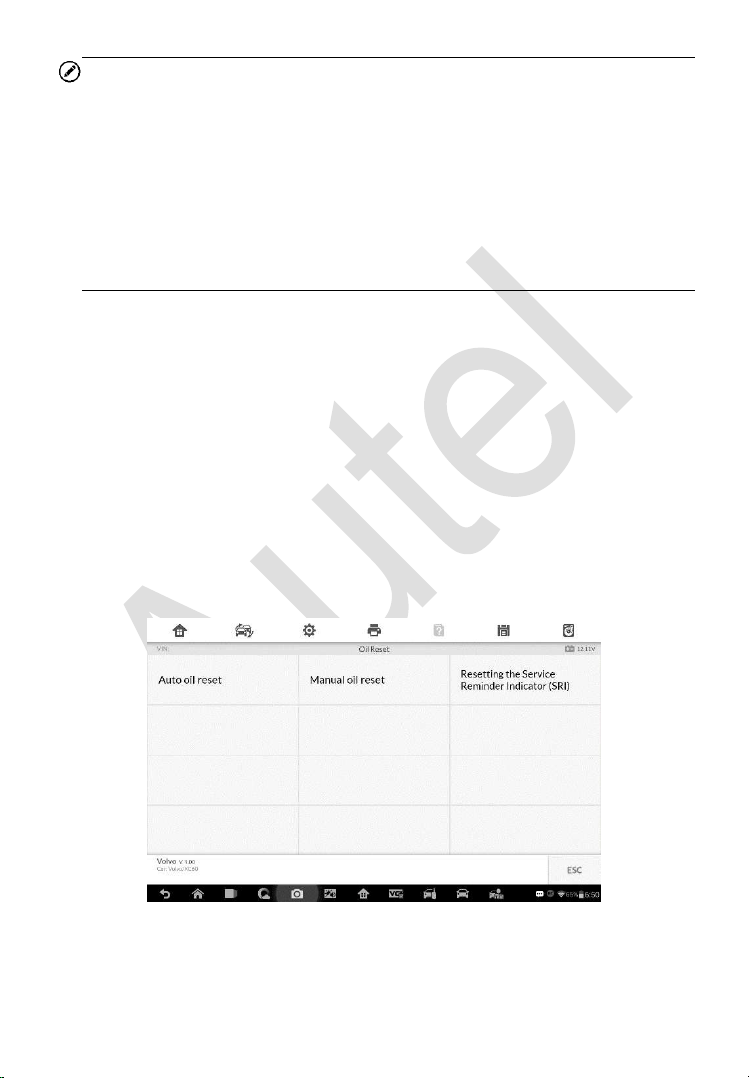
140
NOTE
1. All required work must be carried out before the service indicators are
reset. Failure to do so may result in incorrect service values and cause
DTCs to be stored by the relevant control module.
2. For some vehicles, the scan tool can perform added functionality to reset
additional service lights (maintenance cycle, service interval). Taking
BMW as an example, its service reset function includes engine oil, spark
plugs, front/rear brakes, coolant, particle filter, brake fluid, micro filter,
vehicle inspection, exhaust emission inspection and vehicle check.
All software screens shown in this manual are examples, actual test screens
may vary for each vehicle being tested. Observe the menu titles and on-
screen instructions to make correct option selections.
To perform oil reset functions
1. Tap the Service application button from the MaxiIM Job Menu.
2. Tap Oil Reset button and wait for the vehicle manufacturer screen.
You can tap VIN Scan or the vehicle make to acquire vehicle VIN
information and tap Yes to confirm. See
Vehicle Identification on
page 94 for detail.
3. Tap the function you want in the Oil Reset function list, the list may
vary for different vehicles being tested.
Figure 7-1 Sample Oil Reset Function List
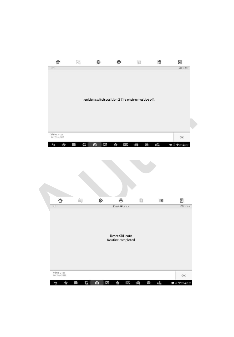
141
4. Follow the step-by-step on-screen instruction to complete the
service. Take Auto oil reset as an example.
5. Tap Auto oil reset on the Oil Reset function list to start the operation.
The screen will notify you to turn the ignition switch to position 2, the
engine must be off.
6. The screen will display Reset SRL data Routine completed once the
operation is successfully done. Tap OK to exit. The operation
procedure varies by function, please follow the onscreen
instructions to complete.
Figure 7-3 Sample Oil Reset Service Screen 2
Figure 7-2 Sample Oil Reset Service Screen 1

142
Electronic Parking Brake (EPB) Service
This function has a multitude of usages to maintain the electronic braking
system safely and effectively. The applications include deactivating and
activating the brake control system, assisting with brake fluid control, opening
and closing brake pads, and setting brakes after disc or pad replacement, etc.
EPB Safety
It may be dangerous to perform Electronic Parking Brake (EPB) system
maintenance, so before you begin the service work, please keep these rules
in mind.
Ensure that you are fully familiar with the braking system and its
operation before commencing any work.
The EPB control system may be required to be deactivated before
carrying out any maintenance/diagnostic work on the brake system. This
can be done from the tool menu.
Only carry out maintenance work when the vehicle is stationary and on
level ground.
Ensure that the EPB control system is reactivated after the maintenance
work has been completed.
NOTE
Autel accepts no responsibility for any accident or injury arising from the
maintenance of the Electronic Parking Brake system.
To perform EPB functions
1. Tap the Service application button from the MaxiIM Job Menu.
2. Tap EPB button and wait for the vehicle manufacturer screen. You
can tap VIN Scan or the vehicle make to acquire vehicle VIN
information and tap Yes to confirm. See
Vehicle Identification on
page 94 for detail.
3. Tap the service you want in the EPB function list, the list may vary
for different vehicles being tested.
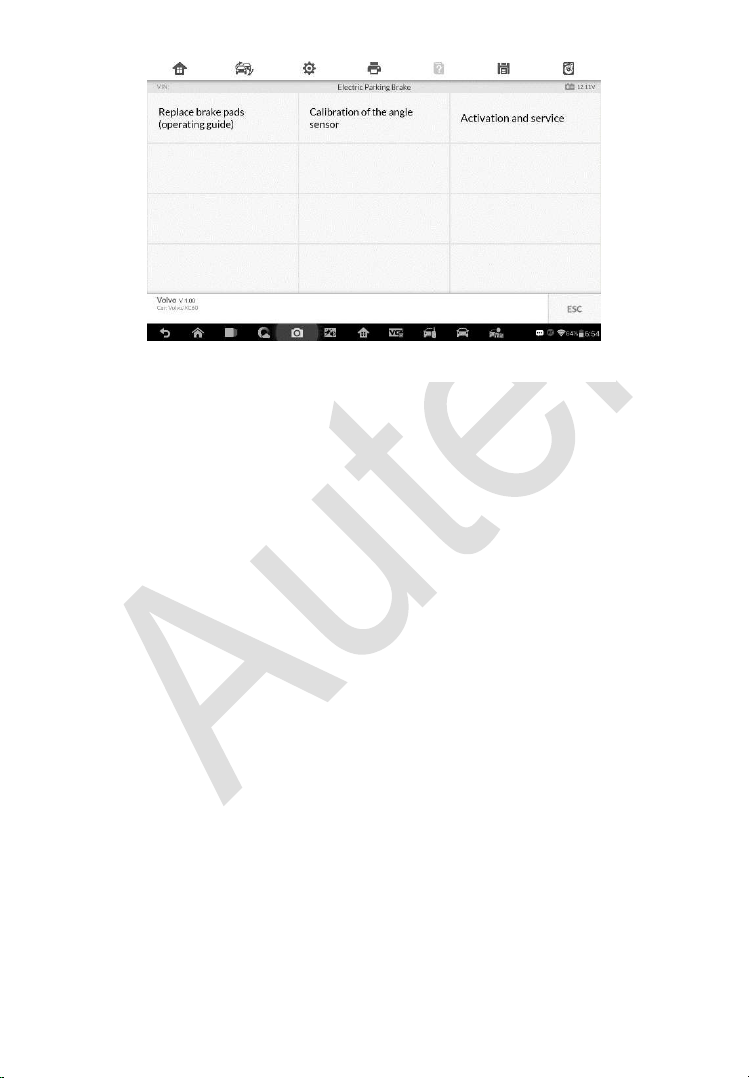
143
4. Follow the step-by-step on-screen instruction to complete the
service.
5. Press OK button to exit.
Calibration of the angle sensor
This service function would calibrate the angle sensor, it must be conducted
after the following repairs:
Replacing an EMF control unit.
Replacing the parking brake button.
1) Tap Start to proceed this service function or the Exit button at the bottom
left to exit.
Figure 7-4 Sample EPB Function List
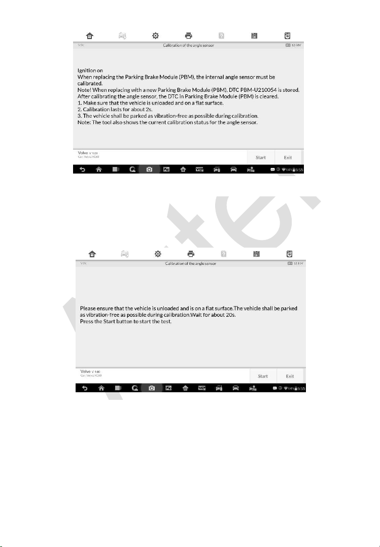
144
2) Ensure the vehicle is unloaded and is on a flat surface. The vehicle shall
be parked as vibration-free as possible during calibration. Wait for about
20s. Press Start to start the calibration.
3) Once the calibration is complete, the screen will display the message
“Calibration completed”. Tap OK to exit.
Figure 7-6 Sample Calibration of the Angle Sensor Screen 2
Figure 7-5 Sample Calibration of the Angle Sensor Screen 1
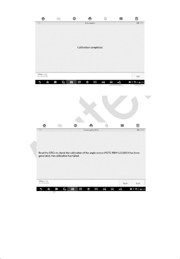
145
4) Read the DTCs to check the calibration of the angle sensor. If DTC PBM-
U210054 has been generated, the calibration has failed. Tap Start to
check the DTCs.
Figure 7-7 Sample Calibration of the Angle Sensor Screen 3
Figure 7-8 Sample Calibration of the Angle Sensor Screen 4
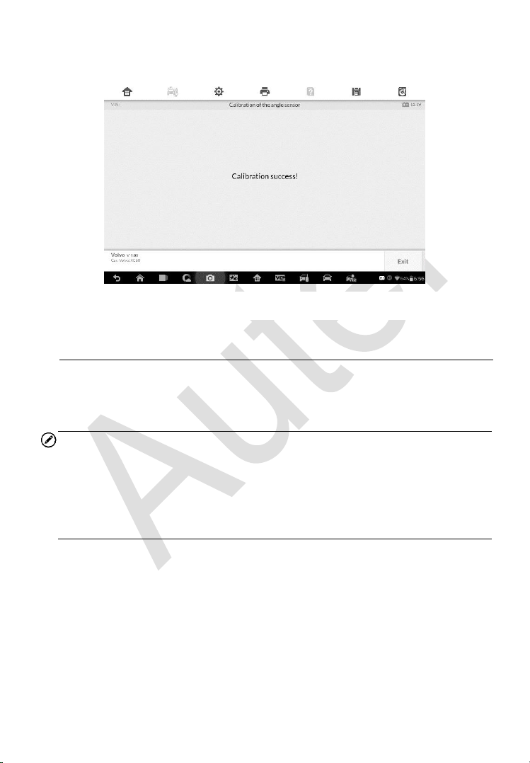
146
5) Once the calibration is successful. The screen displays the message
“Calibration success”. Tap Exit to end the operation.
BMS
The BMS (Battery Management System) allows the scan tool to evaluate the
battery charge state, monitor the close-circuit current, register the battery
replacement, and activate the rest state of the vehicle.
NOTE
1. This function is not supported by all vehicles. The screens shown in this
section are examples.
2. The sub functions and actual test screens of the BMS may vary for
different test vehicles, please follow the on-screen instructions to make
correct option selection.
The vehicle may use either a sealed lead-acid battery or an AGM (Absorbed
Glass Mat) battery. Lead acid battery contains liquid sulphuric acid and can
spill when overturned. AGM battery (known as VRLA battery, valve regulated
lead acid) also contains sulphuric acid, but the acid is contained in glass mats
between terminal plates.
It is recommended that the replacement aftermarket battery has the same
specifications, such as capacity and type, with the battery used in the vehicle.
If the original battery is replaced with a different type of battery (e.g. a lead-
acid battery is replaced with an AGM battery) or a battery with a different
Figure 7-9 Sample Calibration of the Angle Sensor Screen 5

147
capacity (mAh), the vehicle may require reprogramming the new battery type
in addition to performing the battery reset. Consult the vehicle manual for
additional vehicle-specific information.
Reset the information to zero
This option allows displaying the mileage reading of last battery replacement,
registering the battery replacement after replacing a new battery and
informing the power management system that a new battery has been fitted
to the vehicle.
If the battery change is not registered, the power management system will
not function properly, which may not provide the battery with enough charging
power to operate the car and limit the functions of individual electrical
equipment.
Take BMW as an example.
To display the battery history
1. Tap the Service application button from the MaxiIM Job Menu.
2. Tap BMS button and wait for the vehicle manufacturer screen. You
can tap VIN Scan or the vehicle make to acquire vehicle VIN
information and tap Yes to confirm. See
Vehicle Identification on
page 94 for detail.
3. Tap Resetting the information to zero on power supply when
replacing the battery in the EPB function list, the list may vary for
different vehicles being tested.
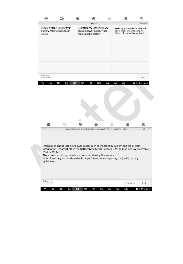
148
Figure 7-10 Sample BMS Function List
4. The stored power supply information is reset using this service.
Resetting to zero should only be performed when replacing the
(main) battery. Once you confirm all the information displayed, tap
Continue to proceed.
5. Tap Start to reset the information to zero.
Figure 7-11 Sample BMS Function Screen 1
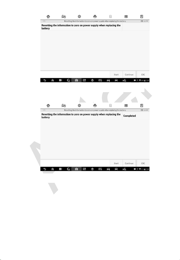
149
6. Once the reset is completed, the screen displays. Tap Continue.
7. For the Battery Monitoring Sensor (BMS) to calculate the correct
battery charging level, the vehicle must be in Sleep mode for a
minimum of 4h after reset. In some cases, 6h in Sleep mode may
be necessary. Read the onscreen instructions carefully and follow
the instructions to ensure vehicle proper functioning.
Figure 7-13 Sample BMS Function Screen 3
Figure 7-12 Sample BMS Function Screen 2
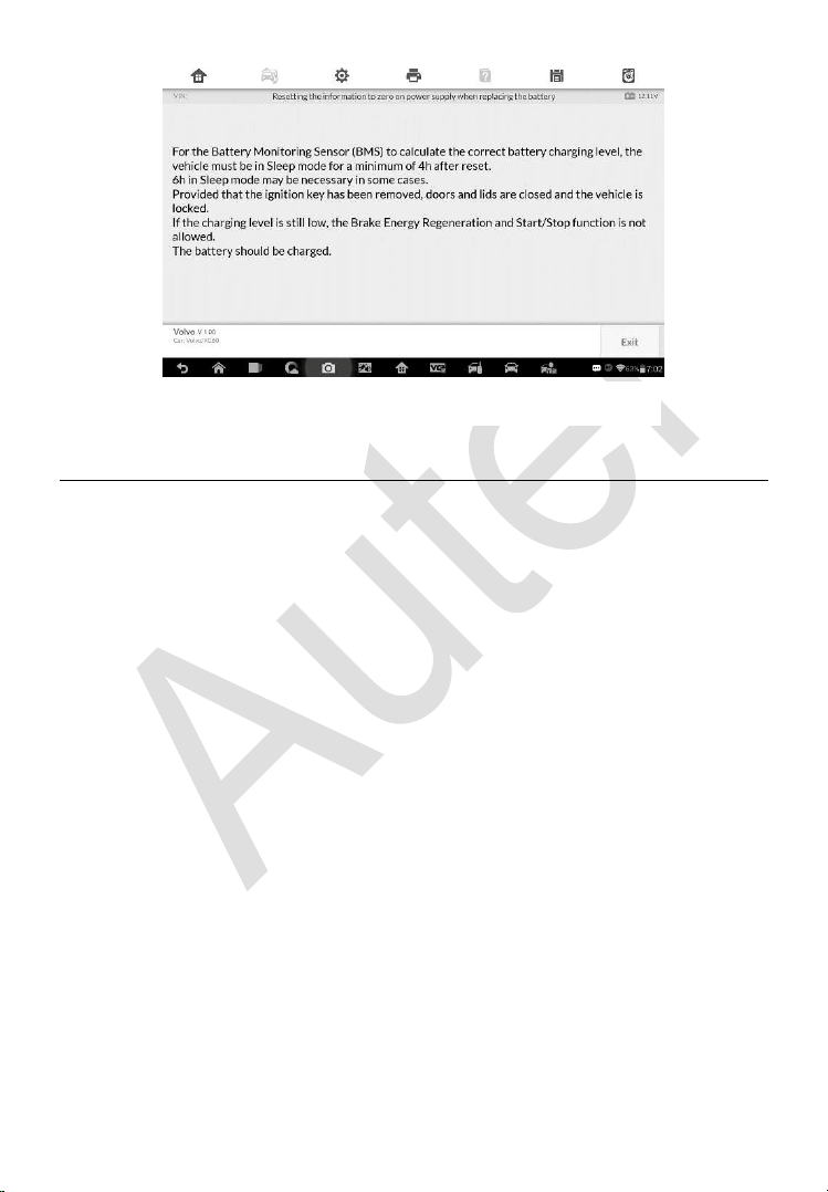
150
Steering Angle Sensor (SAS) Service
Steering Angle Sensor Calibration permanently stores the current steering
wheel position as the straight-ahead position in the steering angle sensor
EEPROM. Therefore, the front wheels and the steering wheel must be set
exactly to the straight-ahead position before calibration. In addition, the
vehicle identification number is also read from the instrument cluster and
stored permanently in the steering angle sensor EEPROM. On successful
completion of calibration, the steering angle sensor fault memory is
automatically cleared.
Calibration must always be carried out after the following operations:
Steering wheel replacement
Steering angle sensor replacement
Any maintenance that involves opening the connector hub from the
steering angle sensor to the column
Any maintenance or repair work on the steering linkage, steering gear or
other related mechanism
Wheel alignment or wheel track adjustment
Accident repairs where damage to the steering angle sensor or assembly,
or any part of the steering system may have occurred
Figure 7-14 Sample BMS Function Screen 4
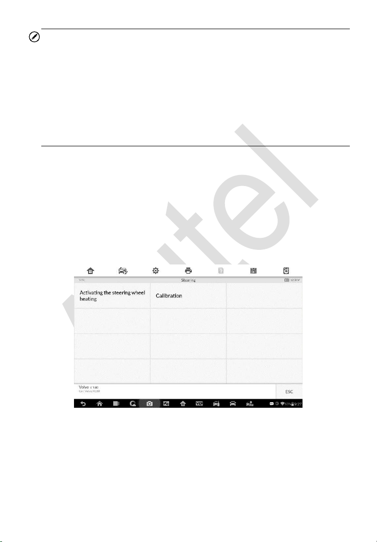
151
NOTE
1. Autel accepts no responsibility for any accident or injury arising from
servicing the SAS system. When interpreting DTCs retrieved from the
vehicle, always follow the manufacturer’s recommendation for repair.
2. All software screens shown in this manual are examples, actual test
screens may vary for each vehicle being tested. Observe the menu titles
and on-screen instructions to make correct option selections.
3. Before starting the procedure, make sure the vehicle has ESC. Look for
the button on dash.
Take Land Rover as an example.
1. Tap the Service application button from the MaxiIM Job Menu.
2. Tap SAS button and wait for the vehicle manufacturer screen. You can
tap VIN Scan or the vehicle make to acquire vehicle VIN information and
tap Yes to confirm. See Vehicle Identification on page 94 for detail.
3. Tap the service you want in the SAS function list, the list may vary for
different vehicles being tested.
Activating the Steering Wheel Heating
This function can be used to activate the Steering Wheel Heating function
directly from the Central Electronic Module (CEM). Upon activation, the
Central Electronic Module (CEM) tries to activate the function despite of the
Figure 7-15 Sample SAS Function Menu
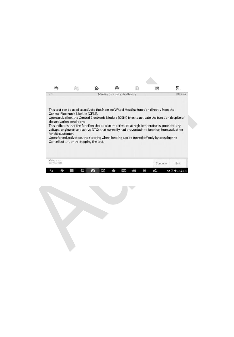
152
activation conditions. This indicates that the function should also be activated
at high temperatures, poor battery voltage, engine off and active DTCs that
normally have prevented the function from activation for the customer. Upon
forced activation, the steering wheel heating can be turned off only by
pressing the Cancel button, or by stopping the test.
1) Tap Activating the Steering Wheel heating from the SAS function
menu to enter the function screen. The screen displays some
notifications, read the notifications carefully and tap Continue.
Figure 7-16 Sample SAS Function Screen 1
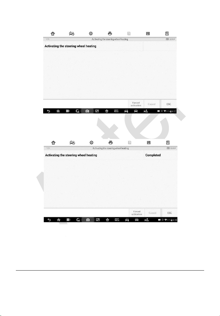
153
2) Tap Forced activation to start the test.
Figure 7-17 Sample SAS Function Screen 2
3) Once the activation is completed, the screen displays as follow. Tap
Forced activation to start the test again or tap ESC to exit.
DPF Service
The DPF function allows you to carry out numerous functions to the Diesel
Particulate Filter system without having to send your car to a main dealer.
Figure 7-18 Sample SAS Function Screen 3

154
The tool will manage DPF regeneration, DPF component replacement teach-
in and DPF teach-in after replacing the engine control unit.
ECM monitors driving style and selects a suitable time to employ regeneration.
Cars driven a lot at idling speed and low load will attempt to regenerate earlier
than cars driven more with high load and high speed. In order for regeneration
to take place, a prolonged high exhaust temperature must be obtained.
In the event of the car being driven in such a way that regeneration is not
possible, i.e. frequent short journeys, a diagnostic trouble code will eventually
be registered, DPF light and “Check Engine” indicator comes on. A service
regeneration can be requested in the workshop, using the diagnostic tool.
Before carrying out a forced DPF regeneration using the tool, check the
following items:
The fuel light is not on.
No DPF-relevant faults stored in system.
The vehicle has the correct spec engine oil.
The oil for diesel is not contaminated.
IMPORTANT
Before diagnosing a problem vehicle and attempting to perform an
emergency regeneration, it is important to obtain a full diagnostic log and read
out relevant measured value blocks.
NOTE
1. The DPF will not regenerate if the engine management light is on, or
there is a faulty EGR valve.
2. The ECU must be re-adapted when replacing the DPF and when topping
up the fuel additive Eolys.

155
3. If the vehicle needs to be driven in order to perform a DPF service,
ALWAYS have a second person help you. One person should drive the
vehicle while the other person observes the screen on the Tool. Trying
to drive and observe the Scan Tool at the same time is dangerous, and
could cause a serious traffic accident.
Resetting the Counter for DPF
This function is used to perform the adaption in the ECM and it is required
following the replacement of DPF.
1. Tap Resetting the Counter for DPF from the service functions menu to
enter the service screen. Tap Continue to proceed.
Figure 7-19 Sample DPF Service Function Menu
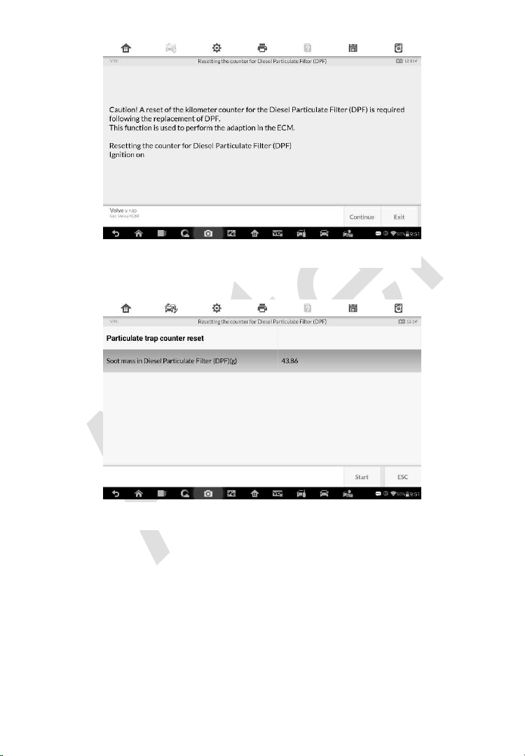
156
2. Tap Start to reset the counter.
3. Wait for 3 seconds, once the reset is complete, the screen displays “The
function is implemented”. Tap Start to reset again or tap ESC to exit.
Figure 7-20 Sample DPF Function Screen 1
Figure 7-21 Sample DPF Function Screen 2
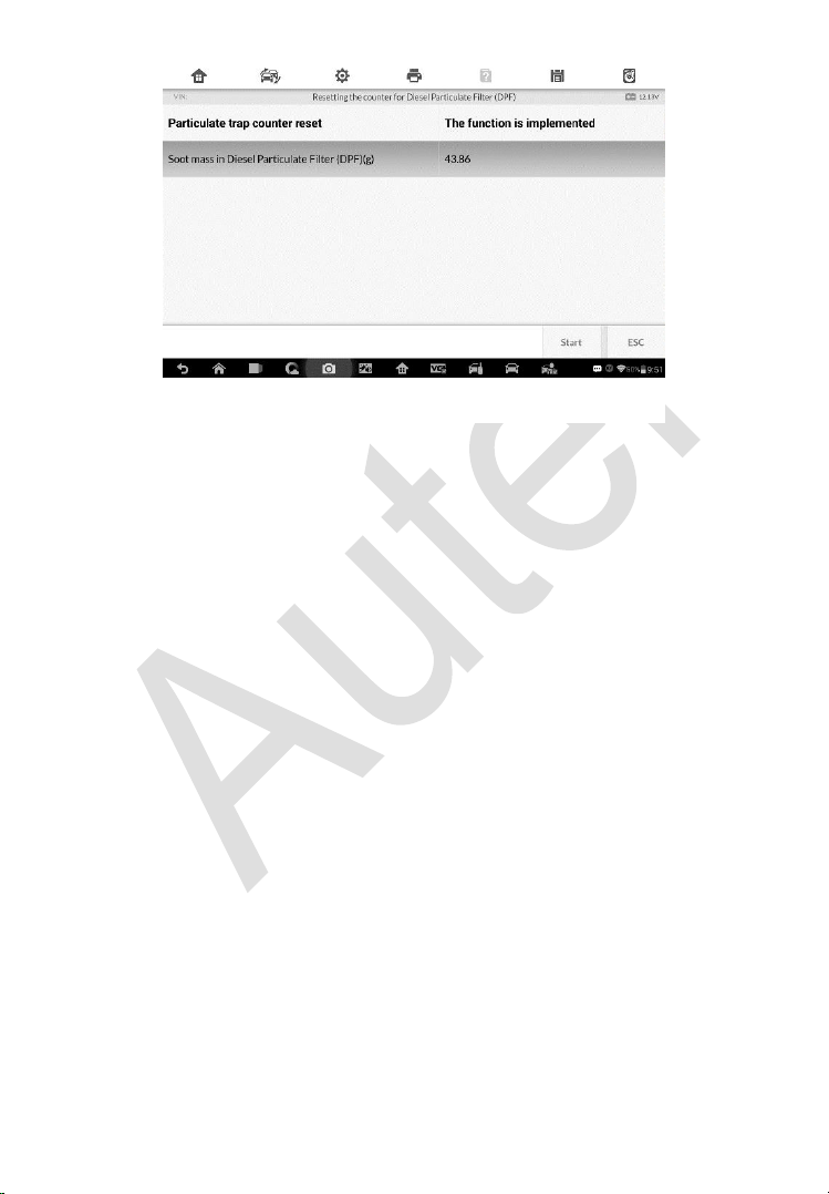
157
Figure 7-22 Sample DPF Function Screen 3
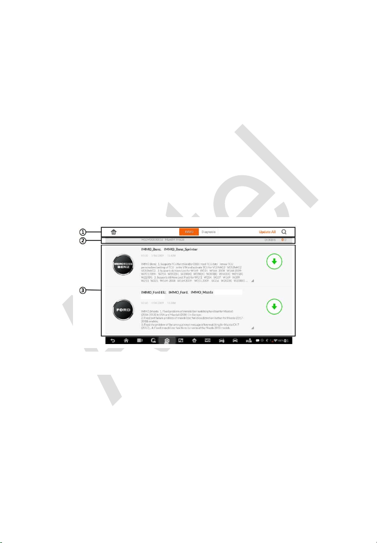
158
8 Update
The Update application allows you to download the latest released software.
The updates can improve the MaxiIM applications’ capabilities, typically by
adding new tests, new models, or enhanced applications to the database.
The Display Tablet automatically searches for available updates for all of the
MaxiIM software when it is connected to the internet. Any updates that are
found can be downloaded and installed on the device. This section describes
installing an update to the MaxiIM System. A notification message displays if
an update is available when the Notifications Center function is enabled in
the Settings application.
1. Navigation and Controls
Home Button – returns to the MaxiIM Job Menu.
Update All – updates all available updates.
IMMO Tab – displays all available IMMO software for vehicles.
Diagnostics Tab – displays all available vehicle diagnostic softwares.
Search Bar – search specific update item by inputting the file name,
for example: a vehicle make.
2. Status Bar
Figure 8-1 Sample Update Screen

159
Left Side – displays the MaxiIM device model information and serial
number.
Right Side – displays an update progress bar indicating the
completion status.
3. Main Section
Left Column – displays vehicle logos and update software version
information; tap the About button displays a function list in PDF
showing more details about the software.
Middle Column – displays a brief introduction about the new
changes to the software operation or capabilities. Tap button to
open an information screen to view more details, and tap the dim
area around to close the window.
Right Column – according to the operation status of each software
item, the button displays differently.
a) Tap Update to update the selected item.
b) Tap Pause to suspend the updating procedure.
c) Tap Continue to go on updating the suspended update.
To update the diagnostic software and TPMS service software
1. Make sure the Display Tablet is connected to a power source with
stable access to the internet.
2. Tap the Update application button from the MaxiIM Job Menu; or
tap the update notification message when received one; or tap the
Update icon on Vehicle Menu in Diagnostics application. The
Update application screen displays.
3. Check all available updates:
If you decide to update all the items of IMMO software, select
IMMO Tab and then tap the Update All button; if you want to
update all items of diagnostic software, select Diagnose Tab
and then tap the Update All button.
If you only want to update one or some of the item(s), tap the
Update button on the right column of the specific item(s).
4. Tap the Pause button to suspend the updating process. When you
tap Continue to renew the update, the updating process will

160
resume from the break point.
5. When the updating process is completed, the firmware will be
installed automatically. The previous version will be replaced.

161
9 Settings
Selecting Settings application opens a setup screen, on which you can adjust
default setting and view information about the MaxiIM system. There are
seven options available for the MaxiIM system settings:
Unit
Language
Printing Setting
Notification Center
Auto Update
About
System Settings
This section describes the operation procedures for the settings.
Unit
This option allows you to adjust the measurement unit for the diagnostic
system.
To adjust the unit setting
1. Tap the Settings application on the MaxiIM Job Menu.
2. Tap the Unit option on the left column.
3. Select the required measurement unit, Metric or English. A tick icon
will display to the right of the selected unit.
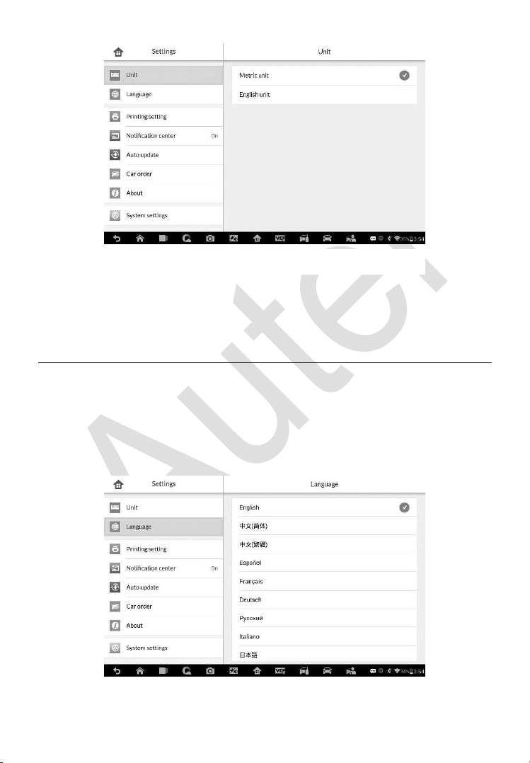
162
4. Tap the Home button on the top left corner to return to the MaxiIM
Job Menu. Or select another setting option for system setup.
Language
This option allows you to adjust the display language for the MaxiIM system.
To adjust the language setting
1. Tap the Settings application on the MaxiIM Job Menu.
2. Tap the Language option on the left column.
Figure 9-1 Sample Unit Screen
Figure 9-2 Sample Language Screen
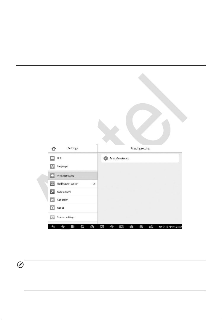
163
3. Select the required language. A tick icon will display to the right of
the selected language.
4. Tap the Home button on the top left corner to return to the MaxiIM
Job Menu. Or select another setting option for system setup.
Printing Setting
This option allows you to print any data or information anywhere and anytime
via Wi-Fi connection.
To setup the printer connection
1. Tap the Settings application on the MaxiIM Job Menu.
2. Tap the Printing Setting option on the left column.
3. Tap the Print via Network item to activate the printing function,
which enables the device to send files to the printer through the PC
via Wi-Fi connection.
4. Tap the Home button on the top left corner to return to the MaxiIM
Job Menu. Or select another setting option for system setup.
NOTE
The Autel Printer runs automatically after the installation. Before printing
make sure the Display Tablet is connected to the same network with the
computer, either via Wi-Fi or LAN. And the computer is connected to a printer.
Figure 9-3 Sample Printing Setting Screen

164
To perform printing via PC
1. Run the Autel Printer on the computer.
2. Click Test Print to make sure the printer is working successfully.
3. Tap the Print button on the toolbar of the Display Tablet. A temporary
document will be created and sent to the computer.
If the Auto Print option in the Autel Printer is selected, the
Autel Printer will print the received document automatically.
If the Auto Print option is not selected, click Open PDF File
button to view all the temporary files. Select the file(s) you want
to print and click Print.
To perform printing via APP
If a Wi-Fi printer is available, please purchase a Wi-Fi printer APP and
install it onto your Display Tablet. By a simple click on the Print button
of a saved file on the Display Tablet, the file will be printed
automatically.
Notification Center
This option allows you to turn the Notification Center function on or off. The
Notification Center function configures the MaxiIM tablet to receive regular
on-line messages from the server for system update notifications or other
service information via the Internet. It is highly recommended to keep this
function on all the time, so you won’t miss out any new update for MaxiIM or
event from Autel. Internet access is required for receiving on-line messages.
To enable the Notification Center function
1. Tap the Settings application on the MaxiIM Job Menu.
2. Tap the Notification Center option on the left column.
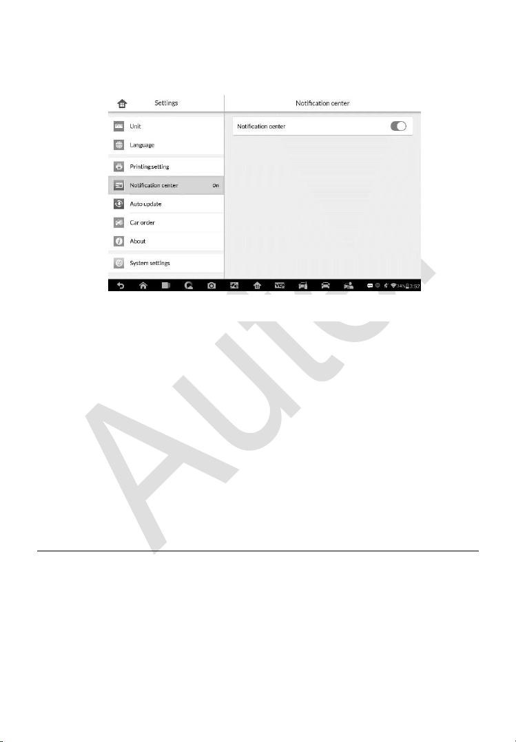
165
3. Tap the ON/OFF button to enable or disable the Notifications
function. If the function is enabled the button turns blue, or if disabled
the button turns gray.
4. Tap the Home button on the top left corner to return to the MaxiIM
Job Menu. Or select another setting option for the system setup.
When the Notification Center function is turned on, and new messages are
received by the MaxiIM device, a notification message displays on the MaxiIM
Job Menu. Press on the message bar and drag it down, and the received
messages are shown in the list, slide the list up or down to view all if the
message list covers more than one screen.
Tapping a specific message launches the corresponding application. For
example, if you tap on an Update notification message, the Update
application will be launched.
Auto Update
The Auto Update allows the tool to automatically update the OS, the MaxiIM
system, and the vehicle software. All you need to do is to switch ON by
tapping the button on the right side of each and set the desired automatic
update time.
To set auto system or vehicle update
1. Tap the Settings application on the MaxiIM Job Menu.
Figure 9-4 Sample Notification Center Screen
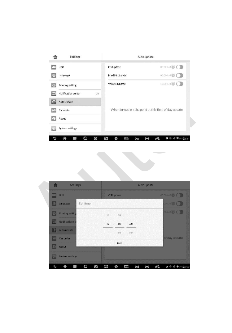
166
2. Tap the Auto Update option on the left column. The three auto
update items list on the right.
3. Switch the ON the button on the right of item that you want to auto
update.
4. Tap on the time to set time, you can use the + and – button or tap
on the numbers then the manual input screen will pop up. Tap Done
to complete the time setting.
Figure 9-6 Sample Set Time Screen
Figure 9-5 Sample Auto Update Screen
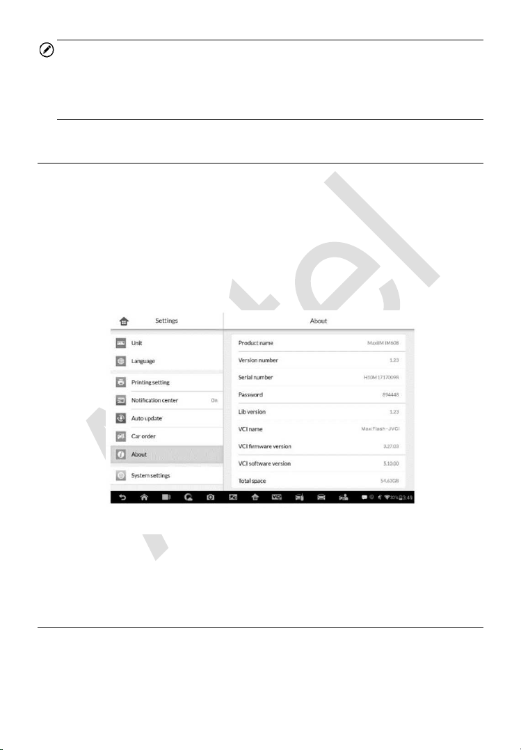
167
NOTE
Internet connection is necessary for auto update, otherwise it would not work
even if you have already switch it on. Make sure the tool is connected to the
Internet for the time you have set.
About
The About option provides information of the MaxiIM diagnostic device
regarding the product name, version, hardware, and serial number, etc.
To check the MaxiIM product information in About
1. Tap the Settings application on the MaxiIM Job Menu.
2. Tap the About option on the left column. The product information
screen displays on the right.
3. Tap the Home button on the top left corner to return to the MaxiIM
Job Menu, or select another setting option for the system setup after
viewing.
System Settings
This option provides you a direct access to the Android background system
setting screen, on which you can adjust various system settings for the
Android system platform, regarding wireless and networks settings, various
Figure 9-7 Sample About Screen

168
device settings such as sound and display, as well as system security settings,
and check the associated information about the Android system, etc.
You may refer to Android documentation for additional information about
Android system settings.
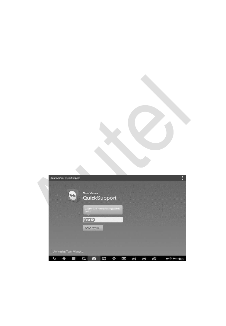
169
10 Remote Desk
The Remote Desk application launches the TeamViewer Quick Support
program, which is a simple, fast and secure remote control screen. You can
use the application to receive ad-hoc remote support from Autel’s support
center, colleagues, or friends, by allowing them to control your MaxiIM tablet
on their PC via the TeamViewer software.
If you think of a TeamViewer connection as a phone call, the TeamViewer ID
would be the phone number under which all TeamViewer Clients can be
reached separately. Computers and mobile devices that run TeamViewer are
identified by a globally unique ID. The first time the Remote Desk application
is started, this ID is generated automatically based on the hardware
characteristics and will not change later on.
Make sure the Display Tablet is connected to the Internet before launching
the Remote Desk application, so that the Display Tablet is accessible to
receive remote support from the third party.
Figure 10-1 Sample Remote Desk Screen
To receive remote support from a partner
1. Power on the Display Tablet.

170
2. Tap the Remote Desk application on the MaxiIM Job Menu. The
TeamViewer screen displays and the device ID is generated and
shown.
3. Your partner must install the Remote Control software to his/her
computer by downloading the TeamViewer full version program
online (
http://www.teamviewer.com), and then start the software on
his/her computer at the same time, in order to provide support and
take control of the Display Tablet remotely.
4. Provide your ID to the partner, and wait for him/her to send you a
remote control request.
5. A popup displays to ask for your confirmation to allow remote control
on your device.
6. Tap Allow to accept, or tap Deny to reject.
Refer to the associated TeamViewer documents for additional information.
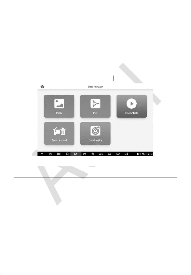
171
11 Data Manager
The Data Manager application is used to store, print, and review the saved
files. Most operations are controlled through the toolbar.
Selecting the Data Manager application opens the file system menu. Different
file types are sorted separately under different options, there are five types of
information files to be viewed or played back.
Operations
Data Manager Operations are based on toolbar controls. Details are
explained in the following sections.
Image Files
The Image section contains all captured screenshot images.
Figure 11-1 Sample Data Manager Main Screen
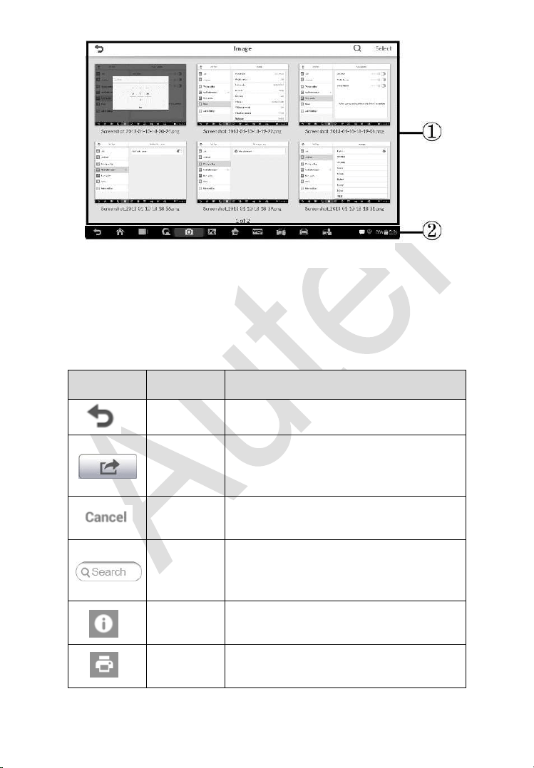
172
1. Toolbar Buttons – used to edit, print and delete the image files. See the
following table for detailed information.
2. Main Section – displays the stored images.
Table 11-1 Toolbar Buttons in Image
Button
Name
Description
Back
Returns to the previous screen.
Enter Edit
Tapping this button shows the editing
toolbar to print, delete or view image
information.
Cancel
Tapping this button close the editing
toolbar or cancels file search.
Search
Quickly locates the image file by
entering the vehicle name, test path, file
name or file info.
Info
Tapping this button opens a window
displaying the details of the image.
Print
Tapping this button prints the selected
image.
Figure 11-2 Sample Image Screen

173
Delete
Tapping this button deletes the selected
image.
To edit image information
1. Select Data Manager application from the MaxiIM Job Menu.
2. Select Image to access the image database.
3. Select an image to display it in full screen.
4. Tap the screen to display the editing toolbar.
5. Tap the Info button to open a window displaying the image
information.
6. Tap the Edit button on the top right corner of the window. The editing
screen displays.
7. Edit the image information by entering the new file name, and file
information.
8. Tap Done to save the information and exit, or tap Cancel to exit
without saving.
NOTE
To realize the wireless data printing function, you need to install the printer
driver program.
To install the printer driver program
1. Please download the Autel PC Suite from
www.autel.com >
Support > Downloads > Autel Update Tools, and install to your PC.
The Autel PC Suite consists of Autel Printer, and Autel PC Suite.
2. Double click on Setup.exe item.
3. Select the installation language and the printer driver installation
wizard will load momentarily.
4. Follow the wizard instructions on the screen and click Next to
continue.

174
5. Click on Install and the printer driver program will be installed onto
the computer.
6. Click on Finish to complete the whole installation procedure.
To delete selected images
1. Select Data Manager application from the MaxiIM Job Menu.
2. Select Image to access the JPG database.
3. Tap the Enter Edit button to display the editing toolbar.
4. Select the images that need to be deleted by tapping the thumbnail
images, the selected thumbnail displays a tick icon at the bottom
right corner.
5. Tap the Delete button, and then Delete Selected, then the selected
images will be deleted.
PDF Files
The PDF section stores and displays all PDF files of saved data. After
entering the PDF database, select a PDF file to view the stored information.
This section uses the standard Adobe Reader application for file viewing and
editing, please refer to the associated Adobe Reader manual for more
detailed instructions.
Review Data
The Review Data section allows you to playback the recorded data frames of
live data streams.
On the Review Data main screen, select a record file to playback.

175
1. Drop-down Toolbar – tap the button at the top center of the screen to
open the Drop-down Toolbar.
2. Main Section – displays the recorded data frames.
3. Navigation Toolbar – allows you to manipulate data playback.
Use the Navigation Toolbar buttons to playback the record data from frame
to frame. Tap Back to exit data playback.
Apps Uninstall
This section allows you to manage the firmware applications installed on the
MaxiIM Diagnostics System. Selecting this section opens a managing screen,
on which you can check all the available vehicle diagnostic applications.
Select the vehicle firmware you want to delete by tapping on the car brand
icon, the selected item will display a blue tick at the upper right corner. Tap
the Delete button on the top bar to delete the firmware from the system
database.
Data Logging
The Data Logging section allows you to launch Support platform directly to
view all records of all sent or unsent (saved) data loggings on the diagnostic
system.
Figure 11-3 Sample Data Playback Screen
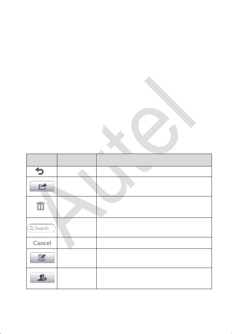
176
12 Shop Manager
The Shop Manager application helps you to manage the workshop
information, customer information records, and keep test vehicle history
records, which can be a great assist in dealing with daily workshop business
and improves customer service. There are three main functions available:
Vehicle History
Workshop Information
Customer Manager
The operations of these functions are mainly manipulated by the toolbar
buttons, which are listed and described in the table below:
Table 12-1 Top Toolbar Buttons in Shop Manager
Button
Name
Description
Back
Returns to the previous screen.
Enter Edit
Shows the editing toolbar to print or delete
the selected file.
Delete
Touching it deletes the selected vehicle
record item from the list.
Search
Quickly locates the vehicle record by
entering the vehicle name or test path.
Cancel
Touching it to cancel edit or file search.
Edit
Touching it allows you to edit information for
the displayed file.
Add
Account
Touching this button to create a new
customer account file.
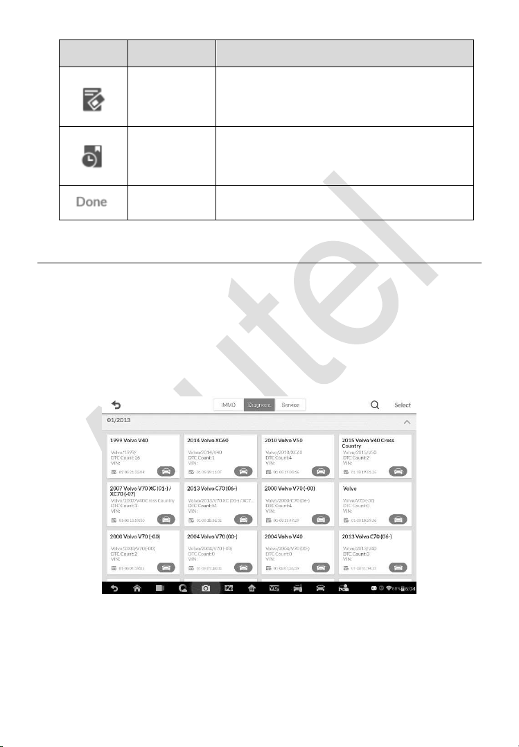
177
Button
Name
Description
History
Notes
Touching this button opens a note form,
which allows you to create audio record,
attach picture or video, or edit text notes, etc.
Vehicle
History
Touching this button opens the Vehicle
History screen which displays the correlated
test vehicle records.
Done
Complete editing and save the file.
Vehicle History
This function stores records of test vehicle history, including vehicle
information and the retrieved DTCs from previous diagnostic sessions, and
displays all information in an easy-to-check table list, on which you can view
summarized details and manually input other information about the test
vehicle and diagnostic loggings, etc. The Vehicle History also provides direct
access to the previously tested vehicle and allows you to restart a diagnostic
session without the need to do vehicle identification again.
1. Top Toolbar Buttons – navigates and makes various controls of the
application. IMMO, Diagnose and Service records are sorted under
respective tabs.
Figure 12-1 Sample Vehicle History Screen

178
2. Main Section – displays all the vehicle history records information.
To activate a test session for the recorded vehicle
1. Tap the Shop Manager application on the MaxiIM Job Menu.
2. Select Vehicle History
3. Tap the Diagnostics button at the bottom of the thumbnail of a
vehicle record item. Or,
4. Select a vehicle record item by tapping the thumbnail.
5. A Historical Test record sheet displays, check the recorded
information of the recorded test vehicle, and tap the Diagnostics
button on the upper right corner.
6. The vehicle’s Diagnostics screen displays, now a new diagnostic
session is activated, see Diagnosis on page 119 for detailed
instructions on vehicle diagnostic operations.
Historical Test Record
The Historical Test record sheet of the tested vehicle is a detailed data form,
which includes all general information of the vehicle such as vehicle year,
make and model, etc., and the diagnostic trouble codes retrieved from the
previous test sessions, as well as other service details which can be added
manually by the technician himself.
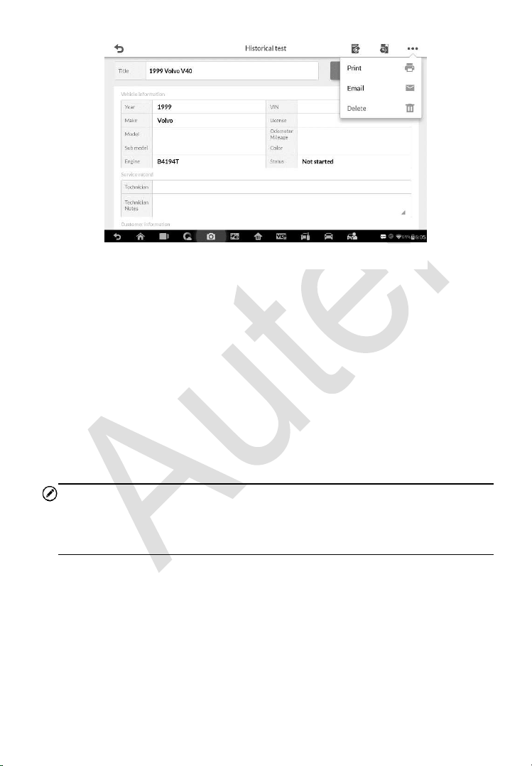
179
To edit the Historical Test record sheet
1. Tap the Shop Manager application on the MaxiIM Job Menu.
2. Select Vehicle History.
3. Select the specific vehicle history record thumbnail from the main
section. The Historical Test record sheet displays.
4. Tap the Edit button to start editing.
5. Tap on each item to input the corresponding information or add
attaching files or images.
NOTE
The vehicle VIN number, or license and the customer information account are
correlated by default. Adding one of the information will automatically
associate the other item in the record sheet, provided that the later one exists.
6. Tap Add to Customer to correlate the Historical Test record sheet
to an existing customer account, or add a new associating account
to be correlated with the test vehicle record. See Customer Manager
on page 180 for more information.
7. Tap Done to save the updated record sheet, or tap Cancel to exit
without saving.
Figure 12-2 Sample Historical Test Record Sheet
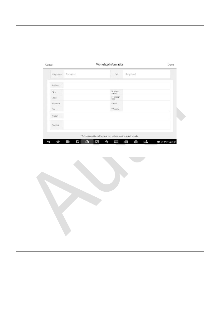
180
Workshop Information
The Workshop Information form allows you to edit, input and save the detailed
workshop information, such as shop name, address, phone number and other
remarks, which, when printing vehicle diagnostic reports and other
associated test file, will appear as the header of the printed documents.
To edit the Workshop Information sheet
1. Tap the Shop Manager application on the MaxiIM Job Menu.
2. Select Workshop Information.
3. Tap the Edit button on the top toolbar.
4. Tap on each field to input the appropriate information.
5. Tap Done to save the updated workshop information sheet, or tap
Cancel to exit without saving.
Customer Manager
The Customer Manager function allows you to create and edit customer
accounts. It helps you to save and organize all customer information accounts
that are correlated with the associated test vehicle history records, which is a
great support for the arrangement of daily workshop business.
Figure 12-3 Sample Workshop Information Sheet

181
To create a customer account
1. Tap the Shop Manager application on the MaxiIM Job Menu.
2. Select Customer Manager.
3. Tap the Add Account button. An empty information form displays,
tap each field to input the appropriate information.
NOTE
The items that must be filled are indicated as required fields.
4. Tap the cross mark beside the Name chart to add a photo. A sub
menu displays, select Take Photo to take a new photo for the
account, or select Choose Photo to choose from the existing files.
5. Some customers may have more than one vehicle for service; you
can always add new vehicle information to the account to be
correlated. Tap Add New Vehicle Information, and then fill in the
vehicle information. Tap the button to cancel adding.
6. Tap Done to save the account, or tap Cancel to exit without saving.
To edit a customer account
1. Tap the Shop Manager application on the MaxiIM Job Menu.
2. Select Customer Manager.
3. Select a customer account by tapping the corresponding name card.
A Customer Information sheet displays.
4. Tap the Edit button on the top toolbar to start editing.
5. Tap on the input field where needs to be altered or supplemented,
and enter updated information.
6. Tap Done to save the updated information, or tap Cancel to exit
without saving.
To delete a customer account
1. Tap the Shop Manager application on the MaxiIM Job Menu.

182
2. Select Customer Manager.
3. Select a customer account by tapping the corresponding name card.
A Customer Information sheet displays.
4. Tap the Edit button on the top toolbar to start editing.
5. Tap the Delete Customer Information button. A confirmation
message displays.
6. Tap OK to confirm the command, and the account is deleted. Tap
Cancel to cancel the request.
History Notes
The History Notes function allows you to add audio and video records, text
notes and photos, to keep multi-media work logs for the associated customer
account, which can be very helpful when dealing with repeat customers.
Keeping notes for each vehicle serviced for each customer will keep you
always on track and well organized in business.
To access History Notes
1. Tap the Shop Manager application on the MaxiIM Job Menu.
2. Select Customer Manager or Vehicle History.
3. Select a customer account by tapping the corresponding name card.
A Customer Information sheet displays (if Customer Manager is
selected). Or, select a vehicle history record item to open the
Historical Test record sheet (if Vehicle History is selected).
4. Tap the History Notes button on the top bar. Now the History Notes
screen displays.
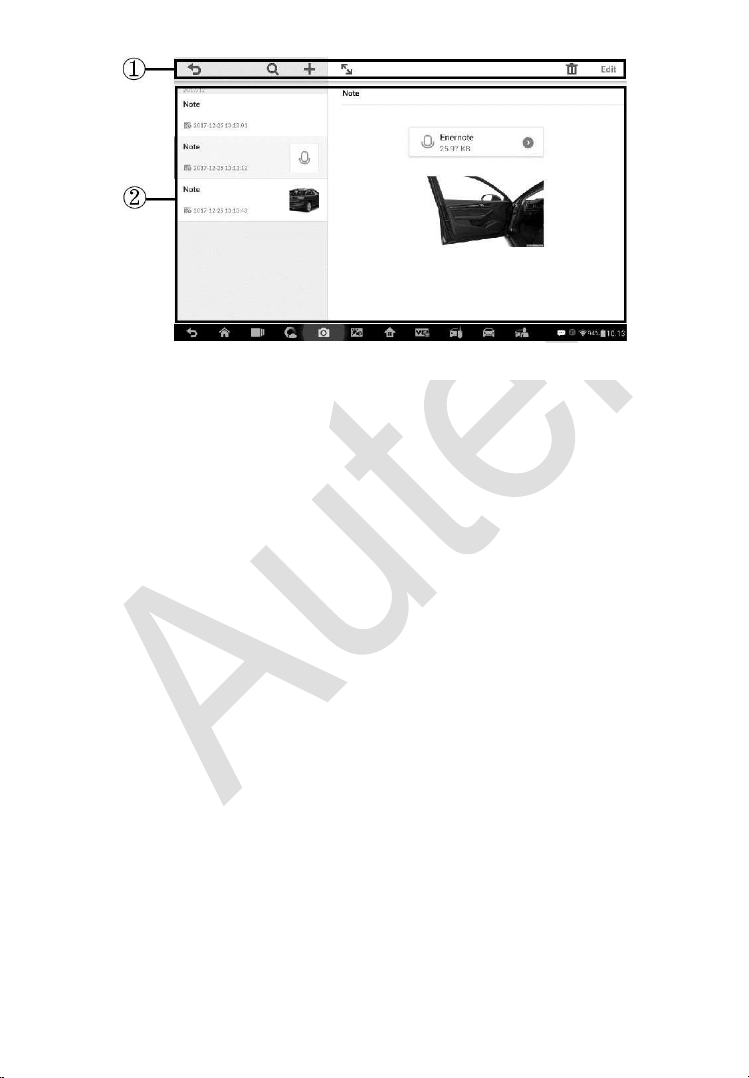
183
1. Functional Buttons – navigates and make various controls of the
function.
2. Main Section – displays the note list on the left column and the detail
information of the selected note on the right column.
To add a note in History Notes
1. Access History Notes.
2. Tap the Add Notes button. An edit window displays.
3. Tap on the Title bar to input a note title.
4. Tap on the blank space below to edit a text note or remark.
5. Select a function button on the top to add files in any form you
choose.
6. Tap Save to save the note; tap Discard or Cancel to exit without
saving.
Figure 12-4 Sample History Notes Screen
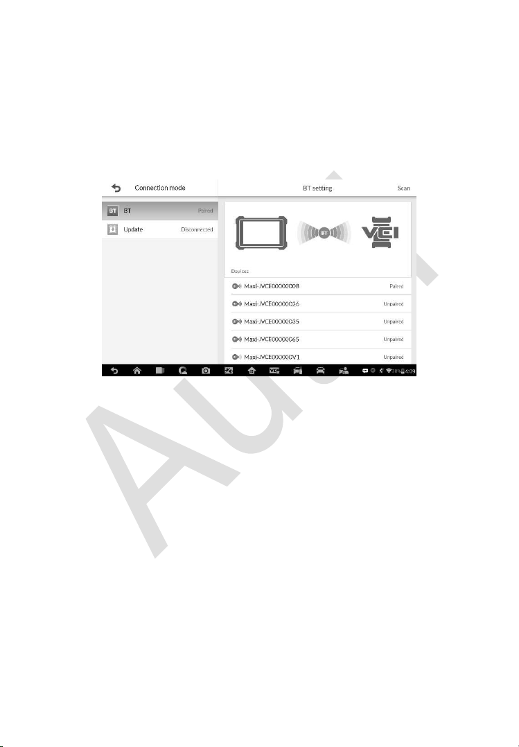
184
13 VCI Manager
This application pairs the tablet with the MaxiFlash, checks the
communication status and update the VCI software.
Figure 13-1 Sample VCI Manager Screen
1. Connection Mode – there are three connection modes available for
selection. The connection state is displayed alongside.
BT Paring – when paired to a wireless device, the connection state
displays as Paired; otherwise it displays as Unpaired.
Update (for VCI software only) – when the MaxiIM tablet and the
MaxiFlash are connected by a USB cable, this function is used to
update VCI software via Internet.
2. BT Setting
The BT Setting screen displays the types and product serial numbers for
all the devices available for pairing. Tap a required device to start pairing.
The BT status icon displayed to the left of the device name indicates the
received signal strength.

185
BT Pairing
The MaxiFlash needs to be connected to a vehicle, so that it is powered
during the synchronization procedure. Ensure the tablet has sufficient battery
life or is connected to an external power supply.
To pair the MaxiFlash with the Tablet
1. Power on the tablet.
2. Insert the 16-pin vehicle data connector of the MaxiFlash to the
vehicle data link connector (DLC).
3. Tap the VCI Manager application on the MaxiFlash Job Menu of the
tablet.
4. Select BT from the connection mode list.
5. Tap the Scan button at the top right corner. Now the device starts
searching for available pairing units.
6. The device name may display as MaxiFlash suffixed with a serial
number. Select the appropriate device for pairing.
7. When paring is successfully done, the connection status displayed
to the right of the device name is shown as Paired.
8. Once paired, the VCI button on the system Navigation bar at the
Connection LED on the MaxiFlash illuminates solid blue. This
signifies that the tablet is connected to the MaxiFlash, and is ready
to perform vehicle diagnosis.
9. Tap the paired device again to unpair it.
10. Tap the Home button on the top left to return to the MaxiIM Job Menu.
NOTE
A MaxiFlash can be paired to only one tablet at a time, and once it’s paired,
the device will not be discoverable to other devices.
Update
When connected to the Internet, this function checks for available update.
When there is a new software version available, tap the displayed Update
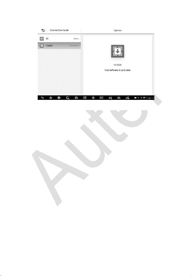
186
button to update. Otherwise, the tablet will display “Your software is up to
date”.
Figure 13-2 Sample Update Screen

187
14 Maintenance and Service
Maintenance Instructions
The following shows how to maintain your devices, together with precautions
to take.
Use a soft cloth and alcohol or a mild window cleaner to clean the touch
screen of the tablet.
Do not use any abrasive cleansers, detergent, or automotive chemicals
to the tablet.
Maintain the devices in dry conditions and keep them within normal
operating temperatures.
Dry your hands before using the tablet. The touch screen of the tablet
may not work if the touch screen is moist, or if you tap the touch screen
with wet hands.
Do not store the devices in humid, dusty or dirty areas.
Check the housing, wiring, and connectors for dirt and damage before
and after each use.
At the end of each work day, wipe the device housing, wiring, and
connectors clean with a damp cloth.
Do not attempt to disassemble your tablet or the VCI unit.
Do not drop or cause severe impact to the devices.
Use only authorized battery chargers and accessories. Any malfunction
or damage caused by the use of unauthorized battery charger and
accessories will void the limited product warranty.
Ensure that the battery charger does not come in contact with conductive
objects.
Do not use the tablet beside microwave ovens, cordless phones and
some medical or scientific instruments to prevent signal interference.

188
Troubleshooting Checklist
A. When the Display Tablet does not work properly:
Make sure the tablet has been registered online.
Make sure the system software and diagnostic application software
are properly updated.
Make sure the tablet is connected to the Internet.
Check all cables, connections, and indicators to see if the signal is
being received.
B. When battery life is shorter than usual:
This may happen when you are in an area with low signal strength.
Turn off your device if is not in use.
C. When you cannot turn on the tablet:
Make sure the tablet is connected to a power source or the battery
is charged.
D. When you are unable to charge the tablet:
Your charger maybe out of order. Contact your nearest dealer.
You may be attempting to use the device in an overly hot/cold
temperature. Try changing the charging environment.
Your device may have not been connected to the charger properly.
Check the connector.
NOTE
If your problems persist, please contact Autel’s technical support personnel
or your local selling agent.
About Battery Usage
Your tablet is powered by a built-in Lithium-ion Polymer battery. This means
that, unlike other forms of battery technology, you can recharge your battery
while some charge remains without reducing your tablet’s autonomy due to
the “battery memory effect” inherent in those technologies.

189
DANGER
The built-in Lithium-ion Polymer battery is factory replaceable only; incorrect
replacement or tampering with the battery pack may cause an explosion.
Do not use a damaged battery charger.
Do not disassemble or open crush, bend or deform, puncture or shred.
Do not modify or remanufacture, attempt to insert foreign objects into the
battery, expose to fire, explosion or other hazard.
Make sure to use the charger and USB cables only that come together
in the package. If you use the other charger and USB cables, you might
incur malfunction or failure of the device.
Only use the charging device that has been qualified with device per the
standard. Use of an unqualified battery or charger may present a risk of
fire, explosion, leakage, or other hazard.
Avoid dropping the tablet. If the tablet is dropped, especially on a hard
surface, and the user suspects damage, take it to a service center for
inspection.
The closer you are to your network’s base station, the longer your tablet
usage time because less battery power is consumed for the connection.
The battery recharging time varies depending on the remaining battery
capacity.
Battery life inevitably shortens over time.
Since over charging may shorten battery life, remove the tablet from its
charger once it is fully charged. Unplug the charger, once charging is
complete.
Leaving the tablet in hot or cold places, especially inside a car in summer
or winter, may reduce the capacity and life of the battery. Always keep
the battery within normal temperatures.

190
15 Compliance Information
FCC Compliance
This device complies with Part 15 of the FCC rules and Industry Canada’s
license-exempt RSSs. Operation is subject to the following two conditions:
1. This device may not cause harmful interference.
2. This device must accept any interference received, including
interference that may cause undesired operation.
Cet appareil est conforme aux CNR exempts de licence d’Industrie Canada.
Son fonctionnement est soumis aux deux conditions suivantes:
1. Ce dispositif ne peut causer des interferences; et
2. Ce dispositif doit accepter toute interférence, y compris les interférences
qui peuvent causer un mauvais fonctionnement de l’appareil.
WARNING
Changes or modifications not expressly approved by the party responsible
for compliance could void the user’s authority to operate the equipment.
NOTE
This equipment has been tested and found to comply with the limits for a
Class B digital device, pursuant to Part 15 of the FCC Rules. These limits are
designed to provide reasonable protection against harmful interference in a
residential installation.
This equipment generates uses and can radiate radio frequency energy and,
if not installed and used in accordance with the instructions, may cause
harmful interference to radio communications. However, there is no
guarantee that interference will not occur in a particular installation. If this
equipment does cause harmful interference to radio or television reception,
which can be determined by turning the equipment off and on, the user is
encouraged to try to correct the interference by one or more of the following
measures:

191
-- Reorient or relocate the receiving antenna.
-- Increase the separation between the equipment and receiver.
-- Connect the equipment into an outlet on a circuit different from that to which
the receiver is connected.
-- Consult the dealer or an experienced radio/TV technician for help.
Changes or modifications not expressly approved by the party responsible for
compliance could void the user’s authority to operate the equipment.
SAR
The radiated output power of this device is below the FCC radio frequency
exposure limits. Nevertheless, the device should be used in such a manner
that the potential for human contact is minimized during normal operation.
The exposure standard for wireless devices employs a unit of measurement
known as the Specific Absorption Rate, or SAR. The SAR limit set by the FCC
is 1.6 W/Kg. Tests for SAR are conducted using standard operating positions
accepted by the FCC with the device transmitting at its highest certified power
level in all tested frequency bands.
Although the SAR is determined at the highest certified power level, the actual
SAR level of the device while operating can be well below the maximum value.
This is because the device is designed to operate at multiple power levels so
as to use only the power required to reach the network. To avoid the possibility
of exceeding the FCC radio frequency exposure limits, human proximity to
antenna should be minimized.
RF WARNING STATEMENT
The device has been evaluated to meet general RF exposure requirement.
The device can be used in portable exposure condition without restriction.
The term “IC” before the radio certification number only signifies that IC
technical specifications were met.
RoHS COMPLIANCE
This device is declared to be in compliance with the European RoHS Directive
2011/65/EU.
CE COMPLIANCE

192
This product is declared to conform to the essential requirements of the
following Directives and carries the CE mark accordingly:
EMC Directive 2014/30/EU
R&TTE Directive 2014/53/EU
Low Voltage Directive 2014/35/EU

193
16 Warranty
Limited One Year Warranty
Autel Intelligent Technology Corp., Ltd. (the Company) warrants to the
original retail purchaser of this MaxiIM Diagnostic Device, that should this
product or any part thereof during normal consumer usage and conditions,
be proven defective in material or workmanship that results in product failure
within one (1) year period from the date of purchase, such defect(s) will be
repaired, or replaced (with new or rebuilt parts) with Proof of Purchase, at the
Company’s option, without charge for parts or labor directly related to the
defect(s).
The Company shall not be liable for any incidental or consequential damages
arising from the use, misuse, or mounting of the device. Some states do not
allow limitation on how long an implied warranty lasts, so the above limitations
may not apply to you.
This warranty does not apply to:
a) Products subjected to abnormal use or conditions, accident, mishandling,
neglect, unauthorized alteration, misuse, improper installation or repair
or improper storage;
b) Products whose mechanical serial number or electronic serial number
has been removed, altered or defaced;
c) Damage from exposure to excessive temperatures or extreme
environmental conditions;
d) Damage resulting from connection to, or use of any accessory or other
product not approved or authorized by the Company;
e) Defects in appearance, cosmetic, decorative or structural items such as
framing and non-operative parts.
f) Products damaged from external causes such as fire, dirt, sand, battery
leakage, blown fuse, theft or improper usage of any electrical source.

194
IMPORTANT
All contents of the product may be deleted during the process of repair. You
should create a back-up copy of any contents of your product before any
repair services.