i
Trademarks
Autel
®
, MaxiSys
®
, MaxiDAS
®
, MaxiScan
®
, MaxiTPMS
®
, MaxiRecorder
®
,
and MaxiCheck
®
are trademarks of Autel Intelligent Technology Corp., Ltd.,
registered in China, the United States and other countries. All other marks
are trademarks or registered trademarks of their respective holders.
Copyright Information
No part of this manual may be reproduced, stored in a retrieval system or
transmitted, in any form or by any means, electronic, mechanical,
photocopying, recording, or otherwise, without the prior written permission
of Autel.
Disclaimer of Warranties and Limitation of Liabilities
All information, specifications and illustrations in this manual are based on
the latest information available at the time of printing. Autel reserves the
right to make changes at any time without notice. While the information in
this manual has been carefully checked for accuracy, no guarantee is given
for the completeness and correctness of the contents, including but not
limited to the product specifications, functions, and illustrations.
Autel is not liable for any direct damages or for any special, incidental, or
indirect damages or for any economic consequential damages (including
lost profits).
IMPORTANT
Before operating or maintaining this unit, please read this manual carefully,
paying attention to the safety warnings and precautions.
For Services and Support:
www.autel.com
1-855-288-3587 (North America)
+86 (0755) 8614-7779 (China)
For details, please refer to Service and Support in this man

ii
CONTENTS
1 SAFETY PRECAUTIONS ................................................................... 1
2 INTRODUCTION ................................................................................ 2
2.1 SPECIFICATIONS ......................................................................... 2
2.2 ACCESSORIES INCLUDED ............................................................. 3
2.3 COMPONENTS AND PORTS ........................................................... 8
2.3.1 USB Port.............................................................................. 9
2.3.2 DC Port ................................................................................ 9
2.3.3 DB 26-Pin Port ..................................................................... 9
2.3.4 Cross-shaped Signal Pin ................................................... 11
2.3.5 Vehicle Key Slot ................................................................ 11
2.3.6 Transponder Slot ............................................................... 11
2.3.7 Infrared Slot ....................................................................... 11
2.3.8 Status Indicator .................................................................. 11
2.3.9 EEPROM Component Transponder Slot ........................... 12
3 PRODUCT TROUBLESHOOTING ................................................... 13
3.1.1 Vehicle Linking Error ......................................................... 13
3.1.2 PC Communication Error ................................................... 13
4 UPDATE ........................................................................................... 14
4.1 SOFTWARE UPDATE .................................................................. 14
4.1.1 Update via Autel’s Tablet ................................................... 14
4.1.2 Update via a Windows PC ................................................. 14

iii
5 COMPLIANCE INFORMATION ........................................................ 15
6 WARRANTY AND SERVICE ............................................................ 17
6.1 LIMITED ONE YEAR WARRANTY.................................................. 17
6.2 SERVICE AND SUPPORT............................................................. 18

1
1 Safety Precautions
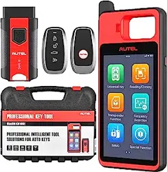
The MaxiProgrammer XP400 Pro has been specially designed to work
with Autel’s IM tablets to aid automotive technicians to program vehicle
keys.
To avoid personal injury or damage to the vehicles, please read this
manual first and observe the following safety precautions whenever
working on a vehicle.
Make sure:
⚫ The diagnosis or service is performed in a safe environment.
⚫ The vehicle is operated in a well-ventilated work area.
⚫ The vehicle parts and the XP400 Pro components are welded at a
constant temperature.
⚫ When welding vehicle parts with the XP400 Pro components, the
unit is powered off and is grounded.
⚫ The XP400 Pro is dry, clean and free from oil, water, grease and
dust.
⚫ Electrostatic interference is avoided during operation. If a failure
occurs due to electrostatic interference, eliminate the interference
and perform the operation again.
2
2 Introduction
The XP400 Pro has the following functions:
(1) Read transponder data (including infrared smart key), and
generate exclusive keys.
(2) Read/write on-board EEPROM chip data, and read/write
MCU/ECU chip data.
(3) Read/write remote control transponder data and detect key
frequency.
Compatible with the key programming diagnostic tablet or a computer
with installed key programming software, the XP400 Pro can read/write
transponder data quickly and accurately.
2.1 Specifications
Table 2-1 Specifications
Item
Description
Operating Temperature
-10℃ ~ 70℃ (14℉ ~ 158℉)
Storage Temperature
-20℃ ~ 85℃ (-4℉ ~ 185℉)
Port
Type B-USB, DB26, DC12
Input Voltage
5 VDC, 12VDC
Operating Current
< 500 mA
3
Item
Description
Maximum Consumption
2.5 W
Device Dimensions (L*W*H)
168 mm * 98 mm * 30 mm
Net Weight
520 g
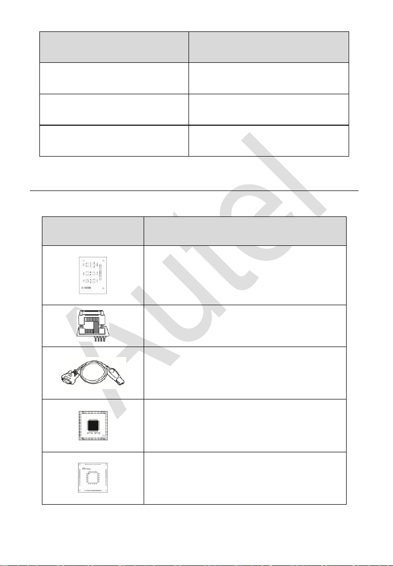
2.2 Accessories Included
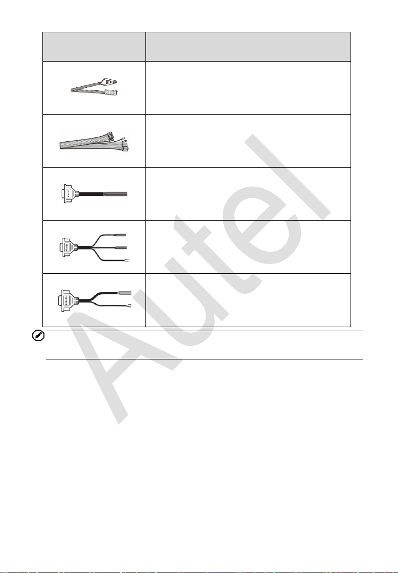
Table 2-2 Accessories
Image
Description
APB129 – EEPROM Adapter
APA002 – EEPROM Socket
APB125 – Infrared Collector
APB103 – MCU_PLCC52 Adapter
APB104 – MCU_FQFP64 Adapter
4
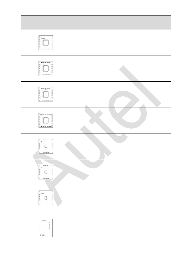
Image
Description
APB105 – MCU_FQFP80 Adapter
APB106 – MCU_FQFP112 Adapter
APB107 – MCU_FQFP144 Adapter
APB108 – MCU_FQFP176 Adapter
APB109 – MCU_FQFP32 Adapter
APB110 – MCU_FQFP48 Adapter
APB111 – MCU_SO28 Adapter
APB113 – PCF79XX Adapter (Optional)
5
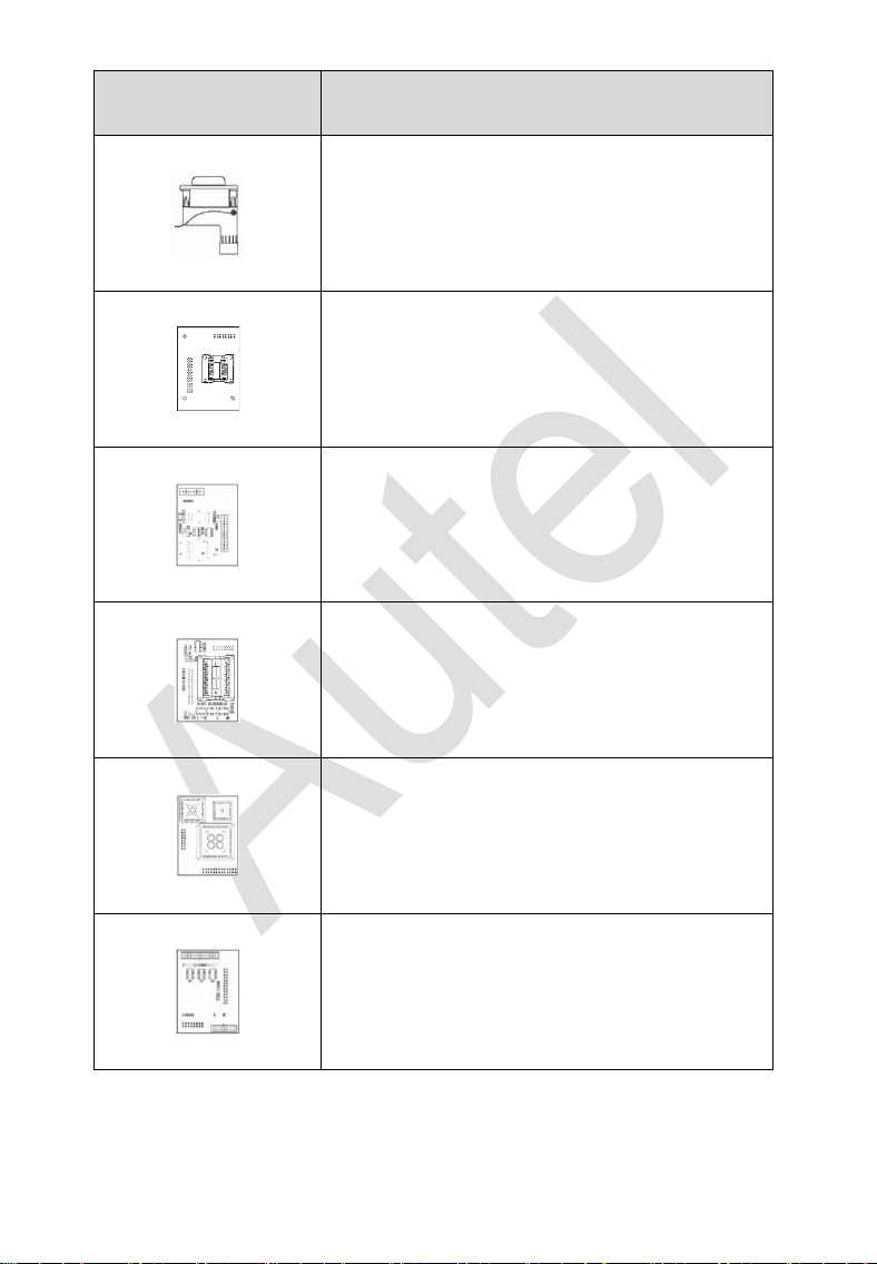
Image
Description
APB114 – EWS3 Adapter (Optional)
APB115 – NEC Adapter Plate (Optional)
APB118 – NEC Steering Lock Adapter
(Optional)
APB119 – TB28FXXX Adapter (Optional)
APB120 – TMS370 Adapter (Optional)
APB121 – AM29FXXX Adapter Plate
(Optional)
6
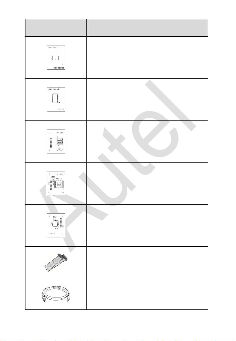
Image
Description
APB122 – AM29FXXX Adapter 1 (Optional)
APB123 – AM29FXXX Adapter 2 (Optional)
APB126 – M35080&D80 Adapter (Optional)
APB127 – MC68HC(7)05BXX Adapter
(Optional)
APB128 – MC68HC05X32 Adapter
(Optional)
APA101 – Spare Signal Cable
APC101 – USB Cable (Standard USB –
Type B USB)
7
Image
Description
APA103 – EEPROM Clamp
Dupont Line
APA107 – ECU Cable
APA108 – MCU Cable
APA109 – MC9S12 Cable
NOTE
Optional Accessories can be purchased separately.
8
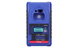
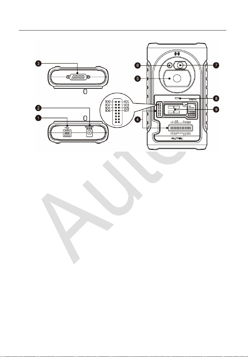
2.3 Components and Ports
Figure 2-1 XP400 Pro Views
1. USB Port – Provides data communication and 5V DC power supply.
2. DC Port – Provides 12V DC power supply.
3. DB 26-Pin Port – connects with the infrared collector, ECU cable,
MCU cable and MC9S12 cable.
4. Cross Signal Pins – holds the MCU spare cable or DIY signal
interface.
5. Vehicle Key Slot – holds the vehicle key.
6. Transponder Slot – holds the transponder.
7. Infrared Key Slot – holds the infrared key.
8. Status LED – indicates the current operating status.
9. EEPROM Component Transponder Slot – holds the EEPROM
plug-in transponder or EEPROM socket.
9
2.3.1 USB Port
The Type B USB port provides data communication and power.
2.3.2 DC Port
DC Port is used to provide 12V power to the XP400 Pro.
2.3.3 DB 26-Pin Port
Four components can be connected to this port: Infrared Collector, ECU
Cable, MCU Cable and MC9S12 Cable.
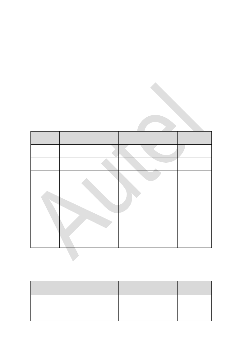
Table 2-3 Definitions of ECU Cable
No.
Color
Definition
Note
1
Red
+12V
2
Black
GND
3
Green
IGN
4
Orange
CANL
5
Blue
CANH
6
Brown
BOOTM
7
Yellow
K
8
White
LIN
Table 2-4 Definitions of MCU Cable
No.
Color
Definition
Note
1
Red and White
VPP1
2
Red and Black
VPP2
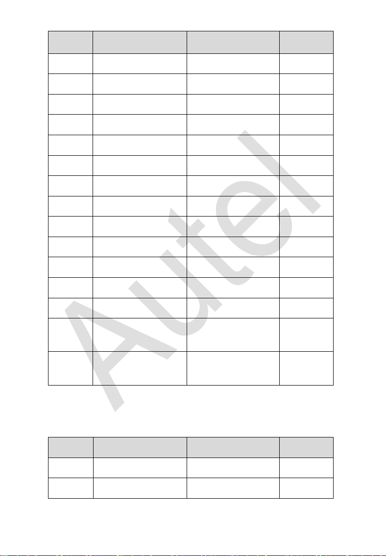
10
No.
Color
Definition
Note
3
Red and Yellow
+12V
4
Red and Blue
VPPR
5
Black
GND
6
Green and White
S0
7
White
S1
8
Brown
S2
9
Gray
S3
10
Blue
S4
11
Red
S5
12
Orange
S6
13
Purple
S7
14
Yellow
S8
15
Green
S9
16
Black
GND
Shielded
Twisted
17
White
OSC
Shielded
Twisted
Table 2-5 Definitions of MC9S12 Cable
No.
Color
Definition
Note
1
Red
+5V
2
Black
GND
11
No.
Color
Definition
Note
3
Green
XCLKS
4
Blue
T/R
5
Yellow
RESET
6
Black
GND
Shielded
Twisted
7
White
OSC
Shielded
Twisted
2.3.4 Cross-shaped Signal Pin
The Cross-shaped signal pin is used to place MCU spare cable or DIY
signal cable to read or write MCU and ECU chips.
2.3.5 Vehicle Key Slot
Holds the vehicle key to read or write vehicle key information.
2.3.6 Transponder Slot
Holds the transponder to read or write transponder information.
2.3.7 Infrared Slot
Holds vehicle key to read or write vehicle key information.
2.3.8 Status Indicator
The Status Indicator shows the current operating status of the XP400
Pro.
12
Table 2-6 Description of the Status Indicator
Indicator
Status
Description
On
Light Green
Powered on and default
Flash Green
Communication
Light Red
Error
2.3.9 EEPROM Component Transponder Slot
Holds the EEPROM plug-in transponder or EEPROM socket to read or
write EEPROM information.

13
3 Product Troubleshooting
This section discusses errors that might occur when using the XP400
Pro and the steps to take to resolve these issues.
3.1.1 Vehicle Linking Error
A communication error occurs if the diagnostic tablet fails to
communicate with the XP400 Pro. Please do the following to correct
the error:
✓ Verify that the XP400 Pro has been authorized by the diagnostic
tablet.
✓ Verify the Internet connection is strong and stable.
✓ Verify that the power LED on the XP400 Pro is lit solid green.
3.1.2 PC Communication Error
A communication error occurs if the XP400 Pro fails to communicate
with PC. Please do the following to correct the error:
✓ Verify that the power LED on the XP400 Pro is lit solid green.
✓ Ensure no firewall software on the PC is preventing communication
and that the USB port is functioning properly.
✓ Ensure the USB communication status LED is blinking green.
Contact technical support if the above steps fail to resolve the
communication error.

14
4 Update
4.1 Software Update
The XP400 Pro software can be updated via the key programming
tablet and a windows-based computer. This section describes two ways
to update the software of the XP400 Pro.
4.1.1 Update via Autel’s Tablet
This function allows you to update the XP400 Pro software via Autel’s
IMMO & Key Programming tablet.
1. Connect the XP400 Pro to Autel’s IMMO & Key Programming
tablet via the supplied USB cable.
2. Verify the power LED light on the front panel is lit solid green.
3. Tap the “Programmer” application on the tablet’s main screen.
4. The tablet will automatically detect the software version
information and download the software update if available.
4.1.2 Update via a Windows PC
This function allows you to update the XP400 Pro software via a
Windows PC. The computer must be connected to the Internet to
update the software on the XP400 Pro.
1. Connect the XP400 Pro to a PC with the supplied USB cable.
2. Verify the power LED on the front panel is lit solid green.
3. Open the PC software. If a firmware update is available for the
XP400 Pro, a message will display to prompt you to update the
software. Otherwise, no message displays.
4. After the update is complete, click the “About” button in the lower
left corner of the PC software to view the current XP400 Pro
firmware, hardware and PC software versions.
15
5 Compliance Information
FCC COMPLIANCE FCC ID: WQ8PRGXP400
This device complies with Part 15 of the FCC rules and Industry
Canada’s license-exempt RSSs. Operation is subject to the following
two conditions:
1. This device may not cause harmful interference.
2. This device must accept any interference received, including
interference that may cause undesired operation.
Cet appareil est conforme aux CNR exempts de licence d'Industrie
Canada. Son fonctionnement est soumis aux deux conditions
suivantes:
1. Ce dispositif ne peut causer des interferences; et
2. Ce dispositif doit accepter toute interférence, y compris les
interférences qui peuvent causer un mauvais fonctionnement de
l'appareil.
WARNING
Changes or modifications not expressly approved by the party
responsible for compliance could void the user's authority to operate
the equipment.
NOTE
This equipment has been tested and found to comply with the limits for
a Class B digital device, pursuant to Part 15 of the FCC Rules. These
limits are designed to provide reasonable protection against harmful
interference in a residential installation.
This equipment generates uses and can radiate radio frequency energy
and, if not installed and used in accordance with the instructions, may
cause harmful interference to radio communications. However, there is
no guarantee that interference will not occur in a particular installation.
If this equipment does cause harmful interference to radio or television

16
reception, which can be determined by turning the equipment off and
on, the user is encouraged to try to correct the interference by one or
more of the following measures:
-- Reorient or relocate the receiving antenna.
-- Increase the separation between the equipment and receiver.
-- Connect the equipment into an outlet on a circuit different from that
to which the receiver is connected.
-- Consult the dealer or an experienced radio/TV technician for help.
RF WARNING STATEMENT
The device has been evaluated to meet general RF exposure
requirement. The device can be used in portable exposure condition
without restriction.
The term “IC” before the radio certification number only signifies that IC
technical specifications were met.
RoHS COMPLIANCE
This device is declared to be in compliance with the European RoHS
Directive 2011/65/EU and amendment Commission Delegated
Directive (EU) 2015/863.
CE COMPLIANCE
This Product is declared to conform to the essential requirements of the
following Directives and carries the CE mark accordingly:
EMC Directive 2014/30/EU
R&TTE Directive 1999/5/EC
Low Voltage Directive 2014/35/EU
17
6 Warranty and Service
6.1 Limited One Year Warranty
Autel Intelligent Technology Corp., Ltd. (the Company) warrants to the
original retail purchaser of this Autel device that should this product or
any part thereof during normal usage and under normal conditions be
proven defective in material or workmanship that results in product
failure within 1 year period from the date of purchase, such defect(s)
will be repaired, or replaced (with new or rebuilt parts) with proof of
Purchase, at the Company’s option, without charge for parts or labor
directly related to the defect(s).
NOTE
IF THE WARRANTY PERIOD IS INCONSISTENT WITH LOCAL
LAWS AND REGULATIONS, PLEASE COMPLY WITH THE
RELEVANT LOCAL LAWS AND REGULATIONS.
The Company shall not be liable for any incidental or consequential
damages arising from the use, misuse, or mounting of the device.
Some states do not allow limitation on how long an implied warranty
lasts, so the above limitations may not apply to you.
This warranty does not apply to:
1) Products subjected to abnormal use or conditions, accident,
mishandling, neglect, unauthorized alteration, misuse, improper
installation or repair or improper storage;
2) Products whose mechanical serial number or electronic serial
number has been removed, altered or defaced;
3) Damage from exposure to excessive temperatures or extreme
environmental conditions;
4) Damage resulting from connection to, or use of any accessory or
other product not approved or authorized by the Company;
18
5) Defects in appearance, cosmetic, decorative or structural items
such as framing and non-operative parts.
6) Products damaged from external causes such as fire, dirt, sand,
battery leakage, blown fuse, theft or improper usage of any
electrical source.
6.2 Service and Support
If you have any questions regarding the product, please contact one of
our offices in your region.
Autel China
Headquarters
⚫ Phone: +86 (0755) 8614-7779 (Monday-Friday,
9AM-6PM Beijing Time)
⚫ Email: [email protected]
⚫ Address: Floor 2, Caihong Keji Building, 36 Hi-
tech North Six Road, Songpingshan Community,
Xili Sub-district, Nanshan District, Shenzhen
City, China
⚫ Web: www.autel.com
Autel North
America
⚫ Phone: 1-855-288-3587 (Monday-Friday, 9AM-
6PM Eastern Time)
⚫ Email: [email protected]
⚫ Address: 36 Harbor Park Drive, Port
Washington, New York, USA 11050
⚫ Web: www.autel.com/us
Autel Europe
⚫ Phone: +49(0)89 540299608 (Monday-Friday,
9AM-6PM Berlin Time)
⚫ Email: [email protected]
⚫ Address: Landsberger Str. 408, 81241
München, Germany
⚫ Web: www.autel.eu
19
Autel APAC
Japan:
⚫ Phone: +81-045-548-6282
⚫ Email: [email protected]
⚫ Address: 6
th
Floor, Ari-nadoribiru 3-7-7,
Shinyokohama, Kohoku-ku, Yokohama-shi,
Kanagawa-ken, 222-0033 Japan
⚫ Web: www.autel.com/jp
Australia:
⚫ Email: [email protected]
⚫ Address: Unit 5, 25 Veronica Street, Capalaba
Autel IMEA
⚫ Phone: +971 585 002709 (in UAE)
⚫ Email: [email protected]
⚫ Address: 906-17, Preatoni Tower (Cluster L),
Jumeirah Lakes Tower, DMCC, Dubai, UAE
⚫ Web: www.autel.com
Autel Latin
America
Mexico:
⚫ Phone: +52 33 1001 7880 (Spanish in Mexico)
⚫ Email: [email protected]
⚫ Address: Avenida Americas 1905, 6B, Colonia
Aldrete, Guadalajara, Jalisco, Mexico
Brazil:
⚫ Email: [email protected]
⚫ Address: Avenida José de Souza Campos n°
900, sala 32 Nova Campinas Campinas – SP,
Brazil
⚫ Web: www.autel.com/br