
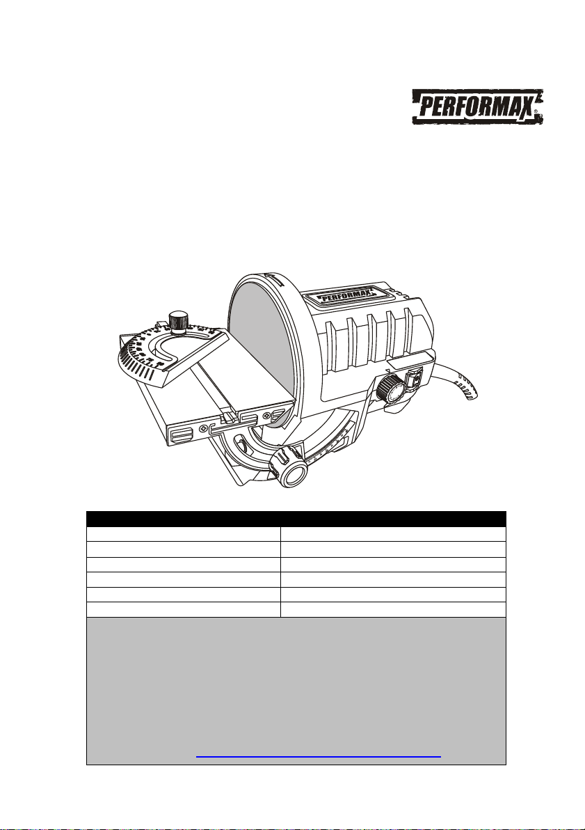
5" BENCH TOP DISC SANDER
240-2905
Owner’s Manual
PRODUCT SPECIFICATIONS
Rating: 120 V, 60 Hz AC
Amperes: 1.1 A
Speed: 1,150 – 3,600 RPM (no load)
Disc diameter: 5" (125mm) self-adhesive surface
Sanding table dimensions: 5 ⅝" x 3 ⅞"
Weight: 5 lb. 8 oz. (2.49 kg)
Need Assistance?
Call us on our toll free customer support line:
1-866-349-8665 (Monday through Friday 9am – 5pm
Eastern Time)
Technical questions
Replacement parts
Parts missing from package
Or email us at: customerservice@powertoolsplus.ca

2
Product specifications ………….………………………………………………………………...
1
Table of contents ……………………………………………………………………..................
2
General safety warnings …………………………………………………………………………
3–4
Eye, ear & lung protection ……………………………………………………………………….
3–4
Electrical safety …………………………………………………………………………………...
4
Power tool safety ……………………………………………………………………..................
5–6
Work area safety
………………………………………………………….……………………...
5
Electrical safety …………………………………………………………………………………...
5
Personal safety …………………………………………………………………………………...
5–6
Power tool use and care .………………………………………………………………………..
6
Service …………………………………………………………………………………………….
6
Specific safety rules ……………………………………………………………………………...
7
Guidelines for extension cords ………………………………………………………………….
8
Symbols ……………………………………………………………………………………………
9
Know your bench top sander ……………………………………………….............................
10
Assembly and operating …………………………………………………………………………
11–14
Clamping the sander to a workbench …………………………………………………………..
11
Removing the sanding table assembly ………………………………………………………...
11
Removing and installing sandpaper ……………………………………………………………
11–12
ON/OFF switch ……………………………………………………………………………………
12
Speed control knob ………………………………………………………………………………..
12
Adjusting the sanding table angle ………………………………………………………………
12
Adjusting the miter angle ………………………………………………………………………...
13
Sanding ……………………………………………………………………………………………
14
Installing the vacuum hose adaptor …………………………………………………………….
14
Maintenance ………………………………………………………………………………………
15
Exploded view …………………………………………………………………………………….
16
Parts list ……………………………………………………………………………………………
17–18
Warranty ……………………………………………………………………….………………….
19
TABLE OF CONTENTS

EYE, EAR & LUNG PROTECTION
This instruction manual includes the following:
General Safety Rules
Specific Safety Rules and Symbols
Functional Description
Assembly
Operation
Maintenance
Accessories
!
ALWAYS WEAR EYE PROTECTION THAT CONFORMS WITH CSA
REQUIREMENTS or ANSI SAFETY STANDARD Z87.1
FLYING DEBRIS can cause permanent eye damage. Prescription
eyeglasses ARE NOT a replacement for proper eye protection.
WARNING: Non-compliant eyewear can cause serious injury if
broken during the operation of a power tool.
WARNING: Use hearing protection, particularly during extended
periods of operation of the tool, or if the operation is noisy.
!
GENERAL SAFETY WARNINGS
WARNING: Before using this tool or any of its accessories, read this
manual and follow all Safety Rules and Operating Instructions. The important
precautions, safeguards and instructions appearing in this manual are not
meant to cover all possible situations. It must be understood that common
sense and caution are factors which cannot be built into the product.
!
SAVE THESE INSTRUCTIONS FOR REFERENCE
3
4
ELECTRICAL SAFETY
GENERAL SAFETY WARNINGS
WEAR A DUST MASK THAT IS DESIGNED TO BE USED WHEN
OPERATING A POWER TOOL IN A DUSTY ENVIRONMENT.
WARNING: Dust that is created by power sanding, sawing, grinding,
drilling, and other construction activities may contain chemicals that are
known to cause cancer, birth defects, or other genetic abnormalities. These
chemicals include:
Lead from lead-based paints
Crystalline silica from bricks, cement, and other masonry products
Arsenic and chromium from chemically treated lumber
The level of risk from exposure to these chemicals varies, according to how
often this type of work is performed. In order to reduce exposure to these
chemicals, work in a well-ventilated area, and use approved safety
equipment, such as a dust mask that is specifically designed to filter out
microscopic particles.
!
WARNING: To avoid electrical hazards, fire hazards or damage to the
tool, use proper circuit protection.
This tool is wired at the factory for 120 V AC operation. It must be
connected to a 120 V AC, 15 A circuit that is protected by a time-delayed
fuse or circuit breaker. To avoid shock or fire, replace power cord
immediately if it is worn, cut or damaged in any way.
SAVE THESE INSTRUCTIONS FOR REFERENCE

5
WARNING: Read all safety warnings
and instructions. Failure to follow the warnings
and instructions may result in electric shock, fire
and/or serious injury.
Save all warnings and instructions for future
reference.
Work area safety
Keep work area clean and well lit. Cluttered or
dark areas invite accidents.
Do not operate power tools in explosive
atmospheres, such as in the presence of
flammable liquids, gases or dust. Power t
ools
create sparks which may ignite the dust or
fumes.
Keep children and bystanders away while
operating a power tool. Distractions can cause
you to lose control.
Electrical safety
Power tool plugs must match the outlet.
Never modify the plug in any way. Do not
use any adapter plugs with earthed
(grounded) power tools. Unmodified plugs and
matching outlets will reduce risk of electric
shock.
Avoid body contact with earthed or
grounded s
urfaces such as pipes, radiators,
ranges and refrigerators. There is an
increased risk of electric shock if your body is
earthed or grounded.
Do not expose power tools to rain or wet
conditions. Water entering a power tool will
increase the risk of electric shock.
Do not abuse the cord. Never use the cord
for carrying, pulling or unplugging the power
tool. Keep cord away from heat, oil, sharp
edges or moving parts. Damaged or
entangled cords
increase the risk of electric
shock.
When operating a power tool outdoors, use
an extension cord suitable for outdoor use.
Use of a cord suitable for outdoor use reduces
the risk of electric shock.
If operating a power tool in a damp location
is unavoidable, use a residual current device
(RCD) protected supply. Use of a ground fault
circuit interrupter (GFCI) reduces the risk of
electric shock.
Personal safety
Stay alert, watch
what you are doing and use
common sense when operating a power tool.
Do not use a power tool while you are tired
or under the influence of drugs, alcohol or
medication. A moment of inattention while
operating power tools may result in serious
personal injury.
Use personal protective equipment. Always
wear eye protection. Protective equipment
such as dust mask, non-skid safety shoes, hard
hat, or hearing protection used for appropri
ate
conditions will reduce personal injuries.
Prevent unintentional starting. Ensure the
switch is in the off-position before
connecting to power source and/or battery
pack, picking up or carrying the tool.
Carrying power tools with your finger on the
switch or energizing power tools that have the
switch on invites accidents.
Remove any adjusting key or wrench before
turning the power tool on. A wrench or a key
left attached to a ro
tating part of the power tool
may result in personal injury.
Do not overreach. Keep proper footing and
balance at all times. This enables better
control of the power tool in unexpected
situations.
Dress properly. Do not wear loose clothing
or jewelery
. Keep your hair, clothing and
gloves away from moving parts. Loose
clothes, jewelery
or long hair can be caught in
moving parts.
POWER TOOL SAFETY
!
SAVE THESE INSTRUCTIONS FOR REFERENCE

6
Personal safety – cont’d
If devices are provided for the connection of
dust extraction and collection facilities,
ensure these are connected and properly
used. Use of dust collection can reduce dust-
related hazards.
Power tool use and care
Do not force the power tool. Use the correct
power tool for your application. The correct
power tool will do the job better and safer at the
rate for which it was designed.
Do not use the power tool if the switch does
not turn it on and off. Any power tool that
cannot be controlled with the switch is
dangerous and must be repaired.
Disconnect the plug from the power source
and/or the battery pack from the power tool
before making any adjustments, changing
accessories, or storing power tools. Such
preventive safety measures reduce the risk of
starting the power tool accidentally.
Store idle power tools out of the reach of
children and do not allow persons unfamiliar
with the power tool or these instructions to
operate the power tool. Power tools are
dangerous in the hands of untrained users.
Maintain power tools. Check for
misalignment or binding of moving parts,
breakage of parts and any other condition
that may affect the power tool’s operation. If
damaged, have the power tool repaired
before use. Many accidents are caused by
poorly maintained power tools.
Keep cutting tools sharp and clean. Properly
maintained cutting tools with sharp cutting
edges are less likely to bind and are easier to
control.
Use the power tool, accessories and tool bits
etc. in accordance with these instructions,
taking into account the working conditions
and the work to be performed. Use of the
power tool for operations different from those
intended could result in a hazardous situation.
Service
Have your power tool serviced by a qualified
repair person using only identical
replacement parts. This will ensure that the
safety of the power tool is maintained.
POWER TOOL SAFETY
SAVE THESE INSTRUCTIONS FOR REFERENCE

7
WARNING: Know your bench top
sander. Do not plug in the sander until you
have read and understand this Instruction
Manual. Learn the tool’s applications and
limitations, as well as the specific potential
hazards related to this tool. Following this rule
will reduce the risk of electric shock, fire, or
serious injury.
Always wear eye protection. Any
power tool can throw foreign
objects into your eyes and cause
permanent eye damage.
ALWAYS wear safety goggles (not glasses) that
comply with ANSI safety standard Z87.1.
Everyday glasses have only impact resistant
lenses. They ARE NOT safety glasses.
WARNING: Glasses or goggles not in
compliance with ANSI Z87.1 could cause
serious injury when they break.
WARNING: Always use a dust mask
when sanding.
WARNING: Always use hearing
protection when sanding, particularly during
extended periods of operation.
WARNING: Always unplug the tool from
the power source before changing the
sandpaper and when cleaning the tool.
Do not wear gloves, neckties or loose clothing.
Never sand material too small to be securely
held.
Make sure there are no nails or foreign objects
in the part of the workpiece to be sanded.
WARNING: When sanding, it is important to
maintain control of the workpiece by firmly
holding it down onto the sanding table and
against the miter gauge (if the miter gauge is
being used). A workpiece that is not held tightly
may become uncontrollable. This is particularly
important when the length of the sanding
surface of the workpiece exceeds 2" (26 mm).
The sanding surface of large workpieces will
contact the upward moving portion of the
sanding disc and the workpiece will be prone to
lifting off the sanding table, possibly causing
loss of control and injury to the operator.
Always keep hands out of the path of the
sanding pad. Avoid awkward hand positions
where a sudden slip could cause your hand to
move into the path of the sanding disc.
To avoid injury from accidental starting, always
remove the plug from the power source before
installing or removing sandpaper or the vacuum
adaptor.
SPECIFIC SAFETY RULES
SAVE THESE INSTRUCTIONS FOR REFERENCE
!
!
!
!
!
SAVE THESE INSTRUCTIONS FOR REFERENCE
!

8
Make sure your extension cord is the proper
size. When using an extension cord, be sure to
use one heavy enough to carry the current the
tool will draw. An undersized cord will cause a
drop in line voltage resulting in loss of power
and overheating. The table on the right shows the
correct size to use according to cord length and
nameplate ampere rating. If in doubt, use the
next heavier gauge. The smaller the gauge
number the heavi
er the cord.
Be sure your extension cord is properly
wired and in good condition. Always replace a
damaged extension cord or have it repaired by a
qualified electrician before using it. Protect your
extension cord from sharp objects, excessive
heat and damp or wet areas.
Use a separate electrical circuit for your
power tools. This circuit must not be less than
14 gauge wire and should be protected with
either a 15A time delay f
use or circuit breaker.
Before connecting the power tool to the power
source, make sure the switch is in the OFF
position and the power source is the same as
indicated on the nameplate. Running at lower
voltage will damage the motor.
WARNING: Repair or replace damaged
or worn extension cords immediately.
Select the appropriate extension cord gauge
and length using the chart on the right.
When operating a power tool outdoors, us
e
an outdoor extension cord marked “W
- A” or
“W”. These cords are rated for outdoor use and
reduce the risk of electric shock.
WARNING: Keep the extension cord
clear of the working area. Position the cord
so it will not get caught on the workpiece,
tools or any other obstructions while you are
working with the power tool.
GUIDELINES FOR EXENSION CORDS
!
MINIMUM GAUGE (AWG) EXTENSION
CORDS (120 V use only)
Ampere rating
Total length in feet
More
than
Not
more
than
7.5 m
(25')
15 m
(50')
30 m
(100')
45 m
(150')
0
6
18
16
16
14
6
10
18
16
14
12
10
12
16
16
14
12
12
16
14
12
Not Applicable
!
SAVE THESE INSTRUCTIONS FOR REFERENCE
9
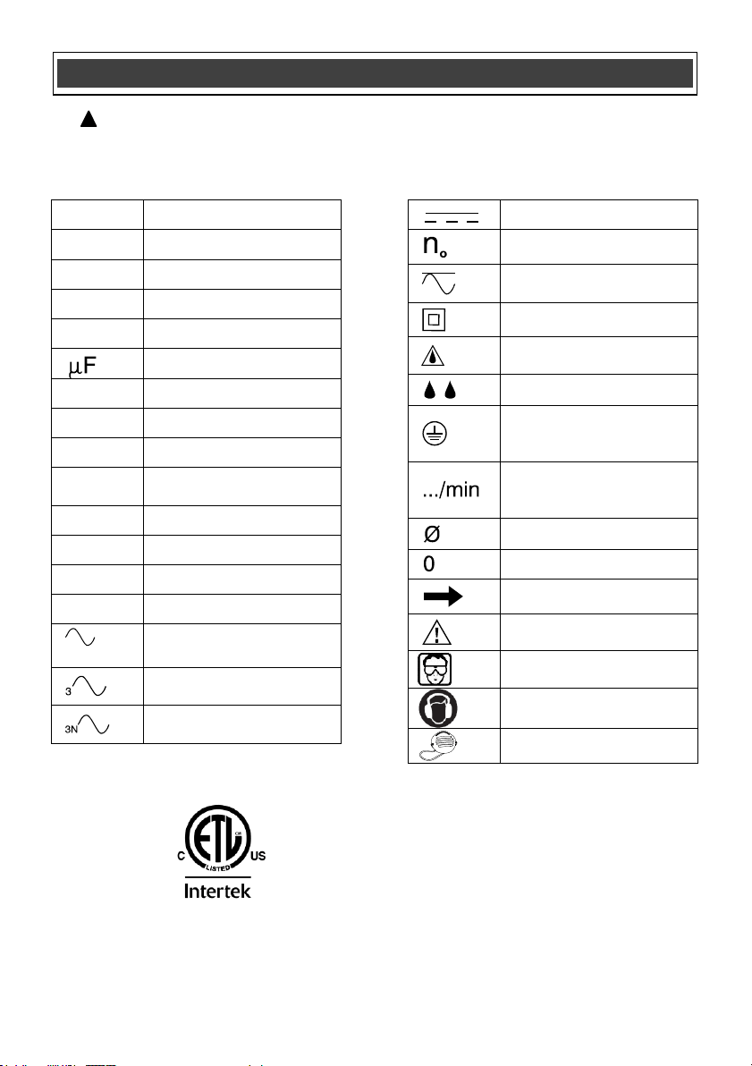
This symbol designates that this tool is
listed with U.S. requirements by ETL
Testing Laboratories, Inc.
Conforms to UL Std. 987.
3042597
JD2504U
LISTED
V
Volts
A
Amperes
Hz
Hertz
W
Watts
kW
Kilowatts
Microfarads
L
Liters
kg
Kilograms
H
Hours
N/cm
2
Newtons per square
centimeter
Pa
Pascals
OPM
Oscillations per minute
Min
Minutes
S
Seconds
or a.c.
Alternating current
Three-phase alternating
current
Three-phase alternating
current with neutral
Direct current
No load speed
Alternating or direct
current
Class II construction
Splash-proof
construction
Watertight construction
Protective grounding at
grounding terminal,
Class I tools
Revolutions or
reciprocations per
minute
Diameter
Off position
Directional arrow
Warning symbol
Wear your safety
glasses
Wear hearing protection
Wear a dust mask
SYMBOLS
WARNING: Some of the following symbols may appear on the bench top sander.
Study these symbols and learn their meaning. Proper interpretation of these symbols
will allow for more efficient and safer operation of this tool.
!
10
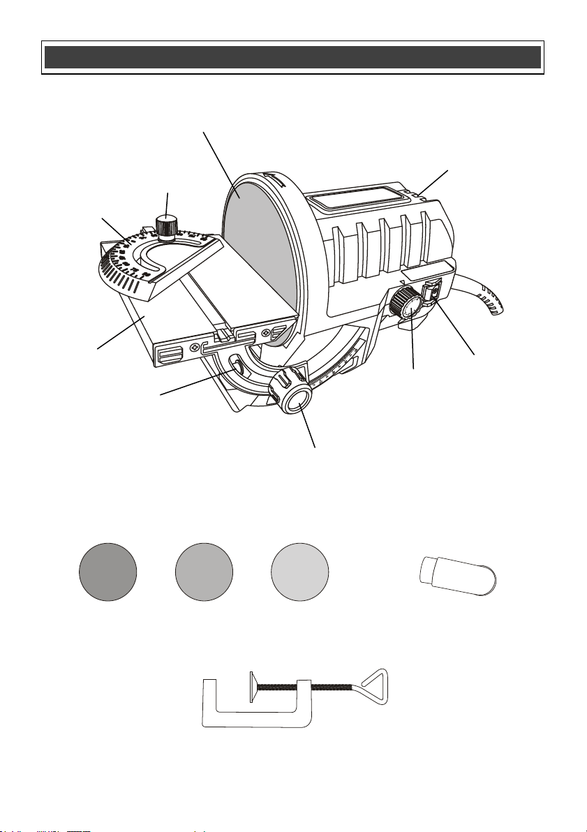
KNOW YOUR BENCH TOP SANDER
Vacuum
hose
adaptor
Sanding disc
2 x 80 grit
Sanding disc
2 x 150 grit
Sanding disc
2 x 240 grit
Sanding table
Motor vents
Sanding plate
ON/OFF
switch
Speed control
knob
Miter gauge
assembly
Miter locking
knob
Sanding table
attachment
screw
Sanding table
Bevel angle
adjusting knob
Clamp
11
F
ig. 1
F
ig. 2
1
2
3
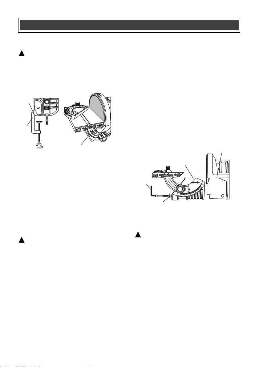
CLAMPING THE SANDER TO A
WORKBENCH
WARNING: Before attempting to use the
sander, it must be securely clamped to a
workbench or similar stable surface. The sander
may be clamped in a vertical position (Fig. 1) or
in its normal horizontal position (Fig. 2) to allow
the sanding disc to be in a vertical position at a
right angle to the work bench.
To clamp the sander to the workbench in the
desired pos
ition, simply open the threaded
clamp screw, insert the top of the clamp (1) into
the clamping cavity (2 or 3) and tighten the
clamp screw until the sander is securely locked
onto the workbench.
REMOVING THE SANDING TABLE
ASSEMBLY
NOTE: The sanding table assembly must be
removed before attempting to install
sandpaper onto the sanding plate.
WARNING: Remove the plug from the
power source before removing the sanding tabl
e
assembly.
1. Insert the 5mm hex key (1) supplied into the
sanding table assembly mounting screw (2)
(Fig. 3).
2. Turn the mounting screw counterclockwise
until both the screw and the washer can be
removed.
3. Slide the sanding table assembly (3) outward
away from the sanding plate.
NOTE: Once the sanding table has been
removed, the sanding disc can be removed
or installed as outlined in Fig. 4 below.
4. To reinstall the
sanding table assembly,
place it against the bottom of the motor
housing (4) and slide it toward the sanding
plate.
NOTE: Make sure the positioning tabs are
fully inserted into the matching slots in the
motor housing.
5. Reinstall the sanding table mounting screw
and washer and tighten it using the 5mm hex
key.
NOTE: Do not overtighten the screw. You
may damage the motor housing.
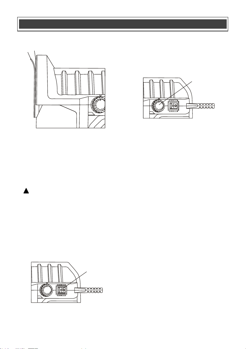
REMOVING AND INSTALLING S
ANDPAPER
WARNING: Remove the plug from the
power source before removing or installing
sandpaper.
1. Remove the sanding table assembly as
noted above.
2. Peel the old sandpaper (1) from the plate (2)
(Fig. 4).
3. Peel the protective paper from the new
sandpaper.
ASSEMBLY AND OPERATING
!
!
4
3
2
1
Fig. 3
!
12
2
Fig. 6
Fig. 4
1
2
REMOVING AND INSTALLING SANDPAPER –
cont’d
4. Clean all sanding dust and debris from the
face of the plate.
NOTE: Any dust or debris on the plate will
prevent the sandpaper from properly
adhering to the plate.
5. Carefully place the glued side of the new
sanding disc onto the sanding plate.
WARNING: The new sandpaper MUST
be centered and firmly pressed onto the plate
to prevent vibration and the possibility of
the
sandpaper flying off the plate when the
sander is turned ON. Serious injury could
result from flying sandpaper.
ON/OFF SWITCH
To turn the sander ON, press the front of the
ON/OFF switch (1) Fig. 5. To turn the sander
OFF, press the rear of the ON/OFF switch.
SPEED CONTROL KNOB
The speed of the sander can be adjusted to suit
the need. To set the sander speed, rotate the
speed control knob (2) (Fig. 6). For the fastest
speed, s
et the speed control knob at #6. For the
slowest speed, set the speed control knob at #1.
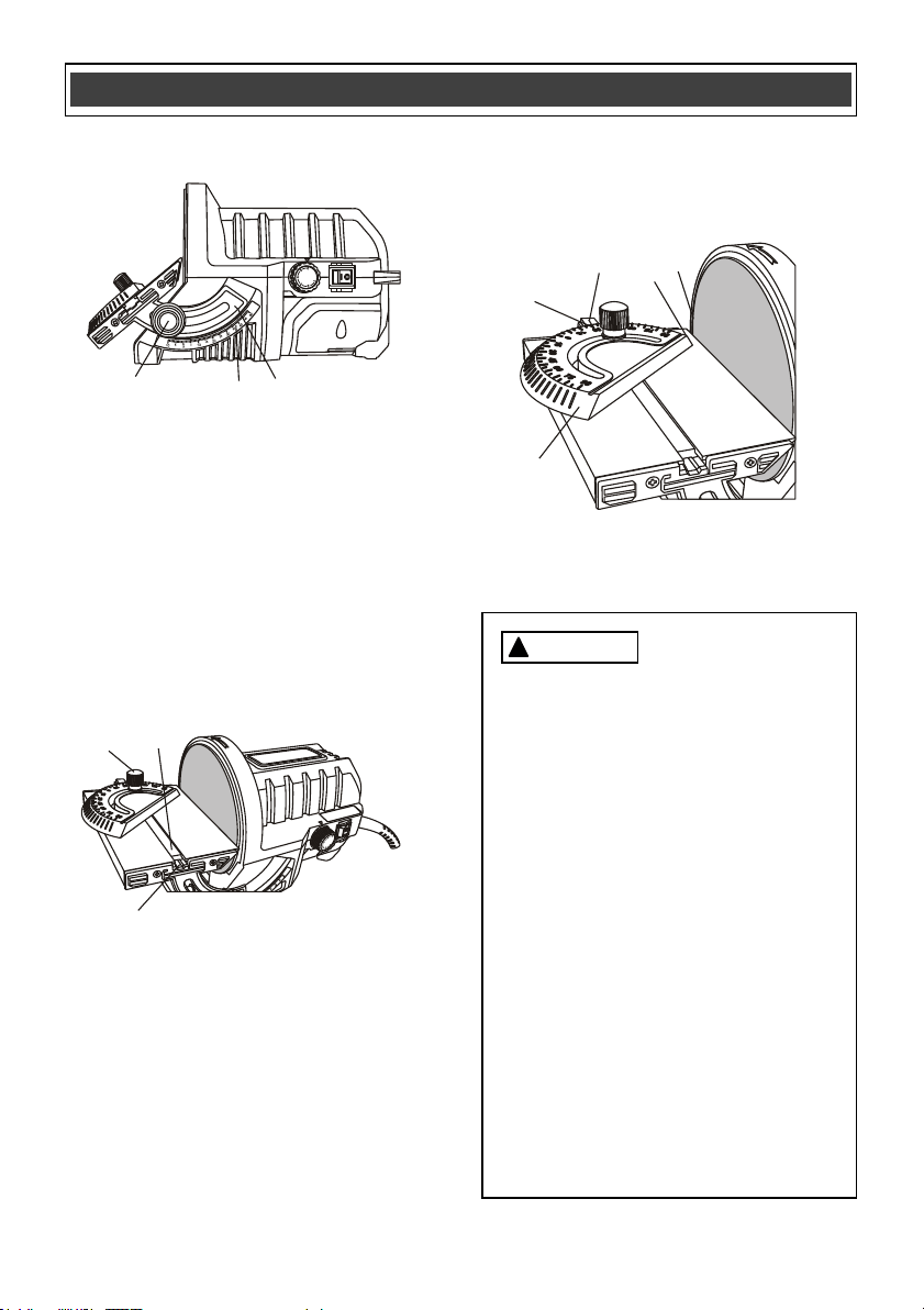
ADJUSTING THE SANDING TABLE ANGLE
The sanding table can be tilted from upward 10°
to downward 50°. Set the sanding table angle as
follows:
1. Loosen the table angle adjustment knob (1)
by turning it counterclockwise (Fig. 7).
NOTE: If the adjustment knob does not
loosen, hold the adjustment knob on the
opposite side of the sanding table w
hile
loosening adjustment Knob (1).
2. When the sanding table adjustment knob is
loose enough, rotate the table downward
until the desired angle (2) is aligned with the
indexing mark (3).
3. Tighten the sanding table adjustment knob.
NOTE: Tighten the adjustment knob with
your hand only. Do not use pliers as you may
overtighten and damage the knob.
4. Test sand a scrap workpiece to make sure
the sanding table angle is correct.
ASSEMBLY AND OPERATING
!
1
Fig. 5
13
ADJUSTING THE SANDING TABLE ANGLE –
cont’d
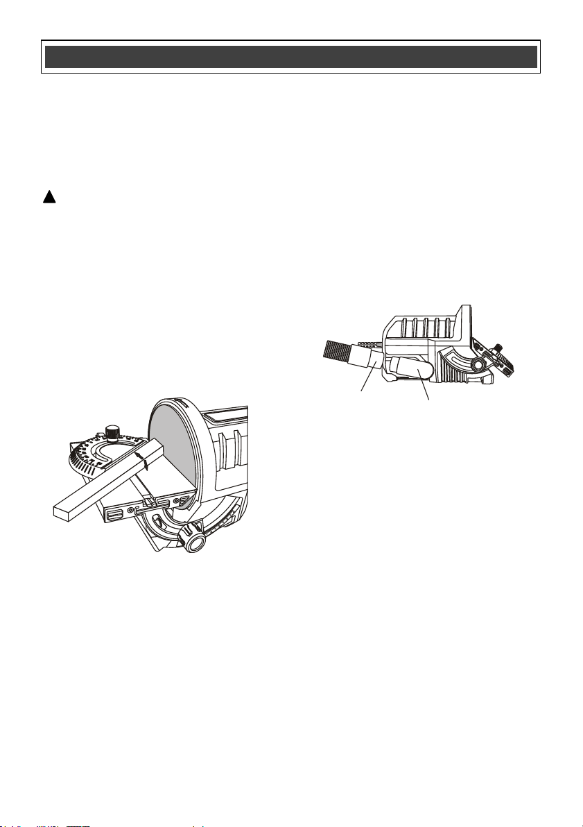
ADJUSTING THE MITER ANGLE
The miter angle can be set to ensure the
sanded surface is held to the correct angle.
1. Loosen the miter adjustment knob (1) by
turning it counterclockwise (Fig. 8).
2. Slide the miter key (2) into the matching slot
(3) in the sanding table.
NOTE: The miter key will not slide fully into
the table slot if it has not been loosened
enough.
3. Rotate the miter gauge (4) and align the
desired angle (5) with the indexing mark (6)
(Fig. 9).
4. Slide the miter gauge assembly in the table
slot so the edge of the miter gauge closest to
the sanding disc (7) is approximately 1/4"
(6.4 mm) inside the outer edge of the
sanding disc (8).
5. Tighten the miter adjusting knob.
NOTE: When the adjusting knob is tightened,
the miter angle will be locked and the miter
assem
bly will be locked in position in the
sanding table slot.
6. Test sand a scrap workpiece to make sure
the miter angle is correct.
1
2
3
Fig. 7
1
2
3
Fig. 8
4
5
6
7
8
Fig. 9
ASSEMBLY AND OPERATING
For safety reasons, the operator must
read the sections of this Owner’s
Manual entitled "GENERAL SAFETY
WARNINGS", "POWER TOOL SAFETY",
"SPECIFIC SAFETY RULES",
"GUIDELINES FOR EXTENSION
CORDS" and "SYMBOLS" before using
this disc sander.
Verify the following every time the disc
sander is used:
1. Sander cord is not damaged.
2. Safety glasses and dust mask are
being worn.
3. Hearing protection is being worn.
4. Sandpaper is the correct type for
the job.
5. Sandpape
r is in good condition and
is properly installed.
6. The workpiece is not too small to
be firmly held while sanding.
Failure to observe these safety rules will
significantly increase the risk of injury.
WARNING
!
14
SANDING
This sander is well suited for fine sanding work
and for making minor material corrections.
Materials that may be sanded with this sander
include all types of wood, steel, non-ferrous and
precious metals, plastics, plexiglass and
fiberglass.
WARNING: When sanding, it is important to
maintain control of the workpiece by firmly
holding it down onto the sanding table and
against the mit
er gauge (if the miter gauge is
being
used) (Fig. 10). A workpiece that is not
held tightly may become uncontrollable. This is
particularly important when the length of the
sanding surface of the workpiece exceeds 2"
(50.8 mm). The sanding surface of large
workpieces will contact the upward moving
portion of the sanding disc and the workpiece
will be prone to lifting off the sanding table,
possibly
causing loss of control and injury to the
operator. Never sand any workpiec
e that is too
small to be firmly held.
It is usually better to use the sander at its
maximum speed setting. Faster speeds will
remove material faster and produce a smoother
finish. Using coarse sandpaper will also facilitate
faster material removal, but produce a rougher
finish. When using the sander to sand sof
t
metals and plastics, using coarser sandpaper
and slower sander speeds will lower the risk of
the materi
al overheating and plugging up the
sandpaper.
INSTALLING THE VACUUM HOSE ADAPTOR
ASSEMBLY AND OPERATING
!
Fig. 10
1
2
Fig. 11
When using the sander for prolonged periods of
time, a vacuum can be attached to the sander to
help reduce the amount of dust escaping into the
work area. To attach a vacuum hose to the
sander, insert the vacuum hose adapter and
ensure the “notch” on the adapter is aligned with
the slot in the inner edge of the tool’s dust port.
Once inserted, turn the adapter clockwise or
counterclockwise, whichever best suits the
position of the tool and/ or that of the vacuum.
Insert the vacuum hose end onto the free end of
the vacuum hose adapter. Please note that the
end of the adapter fits most standard vacuum
hose ends.

15
GENERAL
WARNING: When servicing, use only
identical replacement parts. Use of any other
replacement parts may create a hazard or
cause product damage.
DO NOT use solvents when cleaning plastic
parts. Most plastics are susceptible to damage
from various types of commercial solvents and
may be damaged by their use. Use a clean cloth
to remove dirt, dust, oil, grease etc.
WARNING: Do not at any time allow
brake fluids, gasoline, petroleum-based
products, penetrating oils, etc. to come in
contact with plastic parts. They contain
chemicals that can damage, weaken or
destroy plastic.
DO NOT abuse power tools. Abusive practices
can damage the tool as well as the workpiece.
WARNING: DO NOT attempt to modify
tools or create accessories not
recommended. Any such alteration or
modification is misuse and could result in a
hazardous condition leading to possible
serious injury. It will also void the warranty.
It has been found that electric tools are
subjected to accelerated wear and possible
premature failure when they are used on
fiberglass boats and automotive parts,
wallboard, spackling compounds or plaster. The
chips and grindings from these materials are
highly abrasive to electric tool parts such as
bearings, brushes, commutators, etc.
Consequently, it is not recommended that this
tool be used for extended work on any
fiberglass material, wallboard, spackling
compounds or plaster. During any use on these
materials it is extremely important that the tool is
cleaned frequently by blowing the dust out of the
tool with an air jet.
WARNING: Always wear safety goggles
or safety glasses with side shields during all
sanding operations. It is critical that you also
wear safety goggles or safety glasses with
side shields and a dust mask while blowing
dust out of the sander with an air jet. Failure
to take these safety precautions could result
in permanent eye or lung damage.
LUBRICATION
All of the bearings in this sander are lubricated
with a sufficient amount of high grade lubricant
for the life of the unit under normal conditions.
Therefore, no further lubrication is required.
MAINTENANCE
!
!
!
!
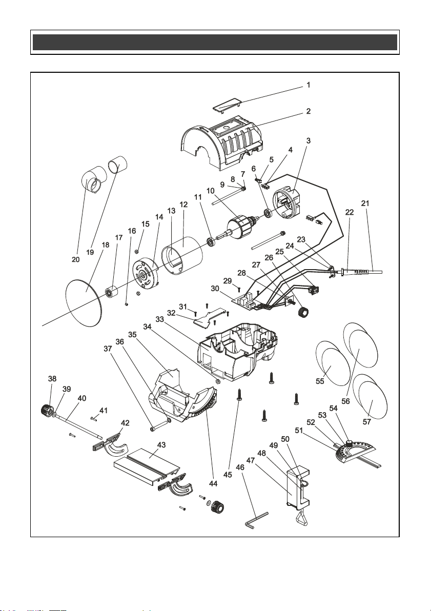
EXPLODED VIEW
16

17
WARNING: When servicing, use only original equipment replacement parts. The use of any
other parts may create a safety hazard or cause damage to the sander.
Any attempt to repair or replace electrical parts on this sander may create a safety hazard unless
repairs are performed by a qualified technician. For more information, call the Toll-free Helpline, at
1-866-349-8665 Eastern Time.
Always order by PART NUMBER, not by key number.
Key #
Part #
Part Name
Quantity
1
3110030023
Label plate
1
2
3011060032
Upper housing
1
3
3160050011
Motor end cover
1 set
4
2030070055
Brush holder
2
5
1230010155
Brush
2
6
4010010048
Bearing 608-2s
1
7
4020010186
Screw M5*10
2
8
4040030003
Snap washer φ5
2
9
4040010011
Washer φ5 x φ10 x 0.8
2
10
1010060035
Rotor
1
11
4010010048
Bearing 608-2rs
1
12
2040310053
Stator sleeve
1
13
2010170031
Magnet block
2
14
3160050011
Motor cover
1 set
15
4060010021
Hex nut M5
2
16
4020150013
Screw M5*16
1
17
3150190198
Insert
1
18
2020160029
5" disc
1
19
3180040004
Dust port nipple
1
20
3180040125
Dust port elbow
1
21
1190030067
UL cord
1
22
3140010091
Cord jacket
1
23
2030050009
Cord clamp
1
24
4030010099
Screw 3.9 x 14
2
25
1061250005
Switch
1
26
3120050002
Speed setting dial
1
27
2030030284
Fix plate
1
28
1210070004
Potentiometer
4
29
4030010136
Screw ST2.9*9
1
30
1130010269
PCB
1
PARTS LIST
!

18
Key #
Part #
Part Name
Quantity
31
4030010136
Screw ST2.9*9
1
32
3180030027
Dust cover
1
33
3011060031
Lower housing
1
34
4060010019
Hex nut M6
1
35
3150160236
Table base
1
36
4040010050
Washer φ6 x φ13 x 2
1
37
4020080036
Screw M6 x 55
1
38
3120060067
Knob
2
39
4040010052
Washer φ6 x φ16 x 0.8
2
40
2040140061
Table mounting screw
1
41
4030020013
Screw T29x16
4
42
3150160237
Bevel support
1set
43
2020210012
Table
1
44
2020070024
Scale label
1
45
4030010106
Screw T3.9*19
4
46
6140020001
Hex nut M5
1
47
2020210013
Clamp
1
48
2040140060
Clamp screw rod
1
49
4100050005
Snap ring
1
50
2030030285
Clamp plate
1
51
3110040011
Miter scale
1
52
2020080045
Graduated miter bar
1
53
4040010009
Washer φ5 x φ12 x 1.5
1
54
1160030053
Miter adjustment knob
1
55
6090040020
Sanding paper P80
2
56
6090040021
Sanding paper P150
2
57
6090040022
Sanding paper P240
2
PARTS LIST

19
Rev 1.5 12/08/2017
PERFORMAX
®
BENCH TOP SANDER WARRANTY
30-DAY MONEY BACK GUARANTEE:
This PERFORMAX
®
brand power tool carries our 30-Day Money Back
Guarantee. If you are not completely satisfied with your PERFORMAX
®
brand
power tool for any reason within thirty (30) days from the date of purchase, return
the tool with your original receipt to any MENARDS
®
retail store, and we will
provide you a refund – no questions asked.
2-YEAR LIMITED WARRANTY:
This PERFORMAX
®
brand power tool carries a 2-Year Limited Warranty to the
original purchaser. If, during normal use, this PERFORMAX
®
power tool breaks
or fails due to a defect in material or workmanship within two (2) years from the
date of original purchase, simply bring this tool with the original sales receipt
back to your nearest MENARDS® retail store. At its discretion, PERFORMAX
®
agrees to have the tool or any defective part(s) repaired or replaced with the
same or similar PERFORMAX
®
product or part free of charge, within the stated
warranty period, when returned by the original purchaser with original sales
receipt. Not withstanding the foregoing, this limited warranty does not cover any
damage that has resulted from abuse or misuse of the Merchandise. This
warranty: (1) excludes expendable parts including but not limited to blades,
brushes, belts, bits, light bulbs, and/or batteries; (2) shall be void if this tool is
used for commercial and/or rental purposes; and (3) does not cover any losses,
injuries to persons/property or costs. This warranty does give you specific legal
rights and you may have other rights, which vary from state to state. Be careful,
tools are dangerous if improperly used or maintained. Seller’s employees are
not qualified to advise you on the use of this Merchandise. Any oral
representation(s) made will not be binding on seller or its employees. The rights
under this limited warranty are to the original purchaser of the Merchandise and
may not be transferred to any subsequent owner. This limited warranty is in lieu
of all warranties, expressed or implied including warranties or merchantability
and fitness for a particular purpose. Seller shall not be liable for any special,
incidental, or consequential damages. The sole exclusive remedy against the
seller will be for the replacement of any defects as provided herein, as long as
the seller is willing or able to replace this product or is willing to refund the
purchase price as provided above. For insurance purposes, seller is not allowed
to demonstrate any of these power tools for you.
For questions / comments, technical assistance or repair parts –
Please Call Toll Free at: 1-866-349-8665 (M-F 8am – 6pm)
SAVE YOUR RECEIPTS. THIS WARRANTY IS VOID WITHOUT THEM.
Distributed by: Menard, Inc., Eau Claire, WI 54703