

WARNING! When using electric tools, m
achines or equipment, basic safety precautions
should always be followed to reduce the risk of fire, electric shock, and personal injury.
1. KE
EP GUARDS IN PLACE and in working order.
2. REMOVE ADJUSTING KEYS AND WRENCHES. Form habit of checking to see that keys and
adjusting wrenches are removed from tool before turning it on.
3. KEEP WORK AREA CLEAN. Cluttered areas and benches invite accidents.
4. DO NOT USE IN DANGEROUS ENVIRONMENT. Do not use power tools in damp or wet
locations, or expose them to rain. Keep work area well lighted.
5. KEEP CHILDREN AWAY. All visitors should be kept safe distance from work area.
6. MAKE WORKSHOP CHILD PROOF with padlocks, master switches, or by removing starter keys.
7. DON’T FORCE TOOL. It will do a better job, and safer at the rate for which it was designed.
8. USE THE RIGHT TOOL. Don’t force tool or attachment to do a job for which it was not designed.
9. USE A PROPER EXTENSION CORD. Make sure your extension cord is in good condition.
When using an extension cord, be sure to use one heavy enough to carry the current your
product will draw. An undersized cord will cause a drop in line voltage resulting in loss of
power and overheating. Table 1 shows the correct size to use depending on cord length
and nameplate ampere rating. If in doubt, use the next heavier gauge. The smaller the gauge
number, the heavier the cord.
10. WEAR PROPER APPAREL. Do not wear loose clothing, gloves, neckties, rings, bracelets, or
other jewelry which may get caught in moving parts. Non-slip footwear is recommended. Wear
protective hair covering to contain long hair.
11. ALWAYS USE SAFETY GLASSES. Also use face or dust mask when cutting. Everyday
eyeglasses only have impact resistant licenses, they are NOT safety glasses.
12. SECURE WORK. Use clamps or a vise to hold work when practical. It’s safer than using your
hand and it frees both hands to operate tool.
13. DON’T OVERREACH. Keep proper footing and balance at all time.
14. MAINTAIN TOOLS WITH CARE. Keep tools sharp and clean for best and safest performance.
Follow instructions for lubricating and changing accessories.
15. DISCONNECT TOOLS before servicing: when changing accessories, such as blades, bits,
cutters, and the like.
16. REDUCE THE RISK OF UNINTENTIONAL STARTING. Make sure switch is in off position
before plugging in.
17. USE RECOMMENDED ACCESSORIES. Consult the owner’s manual for recommended
accessories. The use of improper accessories may cause risk of injury to persons.
2

18. NEVER STAND ON TOOL. Serious injur
y could occur if the tool is tipped or if the cutting tool is
unintentionally contacted.
19. CHECK DAMAGED PARTS. Before further use of the tool, a guard or other part that is damaged
should be carefully checked to determine that it will operate properly and perform its intended
function-check for alignment of moving parts, binding of moving parts, breakage of parts,
mounting, and any other conditions that may affect its operation. A guard or other part that is
damaged should be properly repaired or replaced.
20. DIRECTION OF FEED. Feed work into a blade or cutter against the direction of rotation of the
blade or cutter only.
21. NEVER LEAVE TOOL RUNNING UNATTENDED. TURN POWER OFF. Don’t leave tool until it
comes to a complete stop.
WARNING!
For your own s
afety, do not try to use your belt and disc sander to plug it in until it is completely
assembled and installed according to the instructions, and until you have read and understood this
instruction manual.
1. USE the sander on horizontal surfaces only. Operating the sander when mounted on non-horizontal
surfaces might result in motor damage.
2. TO STOP it from tipping over or moving when in use, the sander must be securely fastened to a
bench top or supporting surface.
3. PLACE the sander so neither the user nor bystanders are forced to stand in line with the abrasive
belt or disc.
4. MAKE SURE the sanding belt is installed in the correct direction. See directional arrow on back of
the belt.
5. ALWAYS have the tracking adjusted properly so the belt does not run off the pulleys.
6. DO NOT USE sanding belts or discs that are damaged, torn or loose. Use only correct size
sanding belt and disc. Narrower belts uncover parts that could trap fingers.
7. MAKE SURE there are no nails or foreign objects in the part of the workpiece to be sanded.
8. ALWAYS HOLD the workpiece firmly when sanding. Keep hands away from sanding belt or disc.
Sand only one workpiece at a time.
9. ALWAYS HOLD the workpiece firmly on the table when using the disc sander and when using the
belt sander.
10. ALWAYS SAND ON THE DOWNWARD SIDE of the sanding disc when using the disc sander.
Sanding on the upward side of the disc could cause the workpiece to fly out of position, resulting in
injury.
11. ALWAYS maintain a minimum clearance of 1.6mm or less between the table or backstop and the
sanding belt or disc.
3

backstop andthe
sanding belt or
disc.
12. DO NOT sand pieces of material that are too small to be safety supported.
13. KEEP fingers away from where the belt goes into the dust trap.
14. WHEN sanding a large workpiece, provide additional support at table height.
15. DO NOT sand with the workpiece unsupported. Support the workpiece with the backstop or
table. The only exception is curved work performed on the outer sanding drum. Plan your
work support.
16. NEVER USE ANOTHER PERSON as additional support for a workpiece longer or wider than
the table.
17. ALWAYS remove scrap pieces and other objects from the table, backstop or belt before
turning the sander ON.
18. NEVER perform layout, assembly or set-up work on the table while the sander is operation.
19. NEVER use solvents to clean plastic parts. Solvents could dissolve or otherwise damage the
material. Use only a soft damp cloth to clean plastic parts.
20. SHOULD any part of your sander be missing, damaged, or fail in any way, or any electrical
components fail to perform properly, shut off switch and remove plug from power supply
outlet. Replace missing, damaged or failed parts before resuming operation.
21. NEVER PULL THE POWER CORD out of the receptacle by pulling on the cord. Keep cords
away from heat, oil and sharp edges.
22. HAVE AN ELECTRICIAN REPLACE OR REPAIR damaged or worn cords immediately.
23. When using the belt to grind or sharpen metal or plastic material:
• DO NOT wet grind or polish. Never use a steady stream of water on the workpiece. Dip or
quench the workpiece in water to cool it.
• DO NOT OVERHEAT THE WORKPIECE. Move the material across the abrasive and allow
it to cool it when it becomes hot.
• DO NOT grind or polish magnesium. It could catch on fire.
24. Do grinding or sanding work at one side at a time.
4
ASSEMBLY AND ADJUSTMENTS
WARNING!
For your own safety, never connect plug to power source outlet until all assembly and
adjustment steps are completed, and you have read and understood the safety and operating
instructions.
WARNING!
When replacing abrasive disc or abrasive belt, or any parts on the sander, turn switch OFF
and remove the plug from the power source.
5
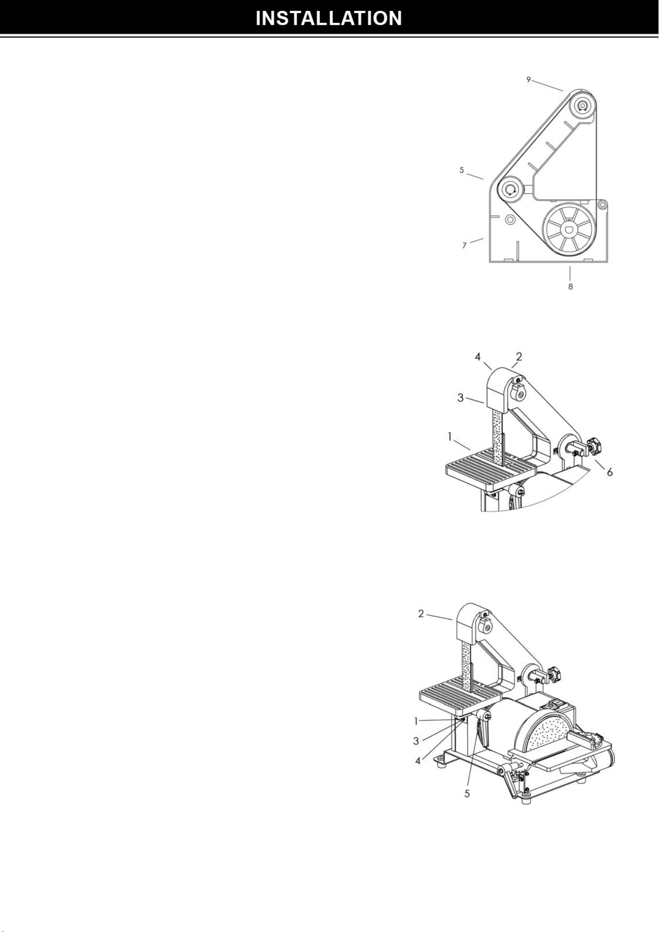
INSTALLING / REPLACING THE 1” X 30”
BELT (FIG. A)
1. Remove the table aligning screw (1) from table.
2. Remove the belt guard (2) and the belt housing (3)
by removing the belt housing knob (4).
3. Release the middle wheel (5) tension by SLIGHTLY
moving and holding the tension handle (6)
downward.
4. Remove the abrasive belt.
5. Install and align the new abrasive belt (7) on the
lower wheel (8) and upper wheel (9). There is an
arrow on the inside of the belt. The arrow should
point down, in the same direction as the rotation
arrow on the housing to avoid belt damage.
6. Release the belt benison handle (6). Spring action
will tension the belt when the handle is released.
7. Make sure the belt is tracking correctly. Adjust the
tracking if necessary. When the belt is tracking
properly it rides on the center of each wheel.
8. Replace the belt guard (2), belt housing (3) and re-
adjust the belt table (1).
Fig. A
INSTALL THE BELT TABLE (FIG. B)
1. Remove the belt guard (2) and the belt housing
(
3) by removing the belt housing knob (4). (Fig. A)
2. Insert the bolt (1) into the hex hole of the bracket from
the left side (belt side) of the sander.
3. Slide the table bracket (3) and the flat washer (4)
onto the bolt.
4. Thread the table handle (5) onto the bolt.
5. Be sure the gap between the belt and table is 1/16”
or less. Turn the handle to lock the table position.
6. Replace the belt guard (2), belt housing (3) and re-
adjust the belt table (1). (Fig. A)
Fig. B
NOTE: The handle can be inserted from the right side if desired.
6
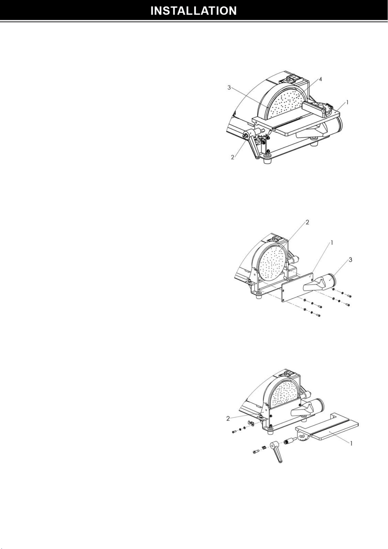
INSTALLING / REPLACING 5” ABRASIVE DISC (FIG. C)
1. Remove the scales
and the table assembly (1) from the sander by
loosening the knob (2) from both sides of the housing.
2. Tilt the table assembly (1) downward to
remove it from the sanding disc plate (3).
3. Remove the dust chute (see Fig. D below).
4. Remove the worn abrasive disc (4) by peeling
it from the metal disc plate (3).
5. Clean the metal disc plate if necessary. Apply
a new adhesive sanding disc to the disc plate.
6. Reattach the dust chute and table assembly
(1).
7. Adjust the table to be 1/16” from the sanding
Fig. C
REMOVING AND INSTALLING THE DUST CHUTE
(FIG. D)
1. Remove or attach the dust chute (1) to the disc
guard housing (2) using the four screws.
2. The dust chute exhaust (3) must point to the
side of the sander as shown.
Fig. D
ASSEMBLE THE DISC TABLE (FIG. E)
1. A
lign the disc table (1) with the holes on
the disc guard (2).
2. Attach scales to hole on the disc
guard housing. Tighten the screws.
3. Attach knobs (3) and washers (4), tighten
the table and guard together.
4. Be sure the gap between the disc and
disc table is 1/16” or less.
Fig .E
7
M
ITER GAUGE (FIG. F)
A miter gauge (1) is supplied with your sander and is
used with the disc table. The miter gauge body can be
turned 0
0
to 45
0
right or left for angle or miter sanding.
Loosen knob (2), rotate miter gauge body to the
desired angle and tight lock knob (2)
Fig. F
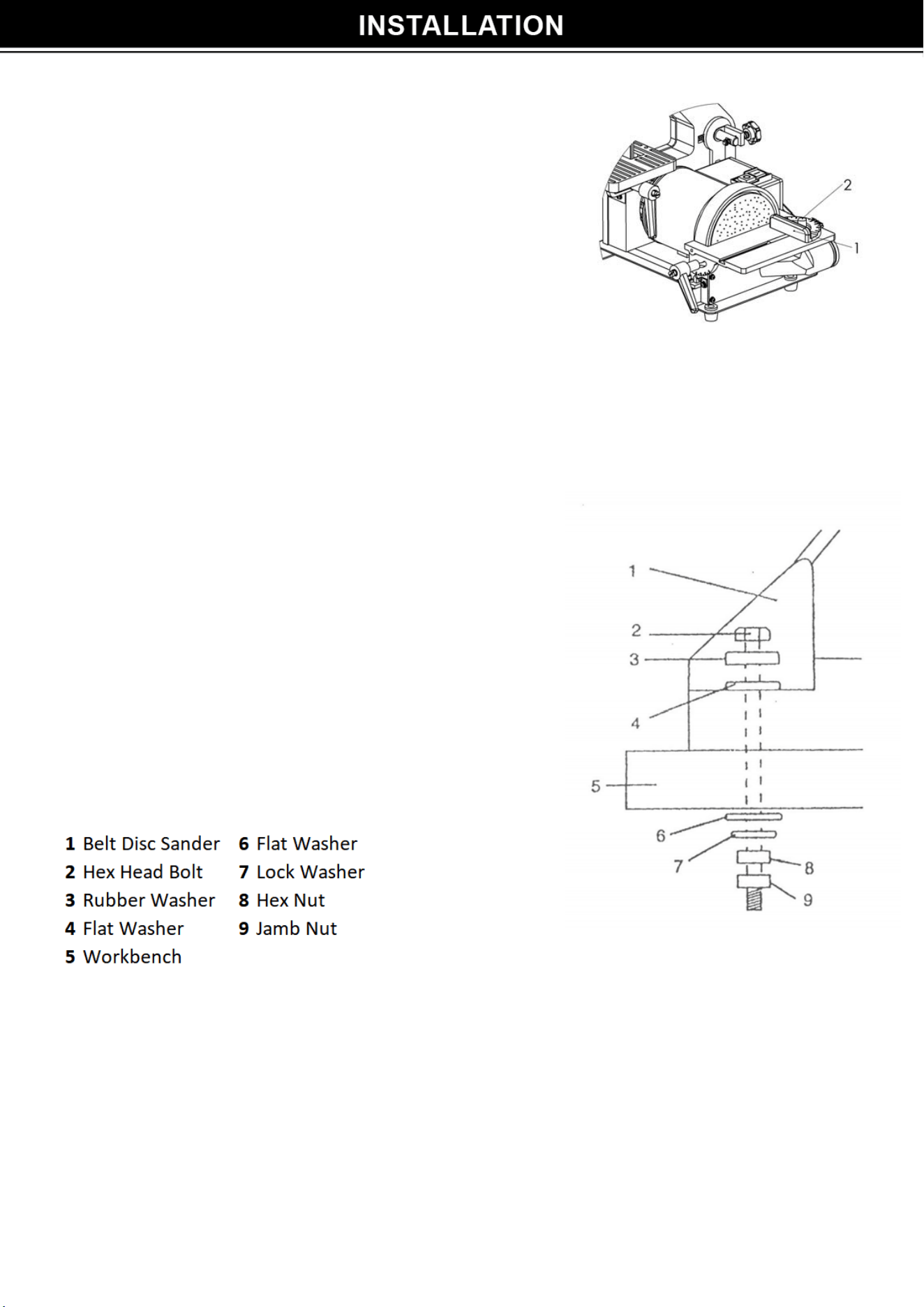
FASTENING SANDER TO WORK SURFACE (FIG. G)
1. To mount your s
ander in a permanent location
such as a sturdy workbench, bolt the base of the
sander to a solid workbench top. The base of
the sander has 4 mounting holes.
2. Place the sander on the work surface, mark the
holes on the work surface and drill 3/8” holes.
Use bolts, washers and nuts to secure.
3. If the workbench moves or shakes during
operation, the workbench must be fastened to
the floor.
4. Your sander is designed to be used on horizontal
surface only. Motor damage may result when
mounted on a non-horizontal surface.
Fig. G
NOTE: Secure tool to suppor
ting structure as tool may tip, slide, or walk on supporting structure.
8
ADJUSTMENT INSTRUCTIONS
WARNING!
Always turn the switch OFF and unplug the power cord from the outlet before adjusting your sander.
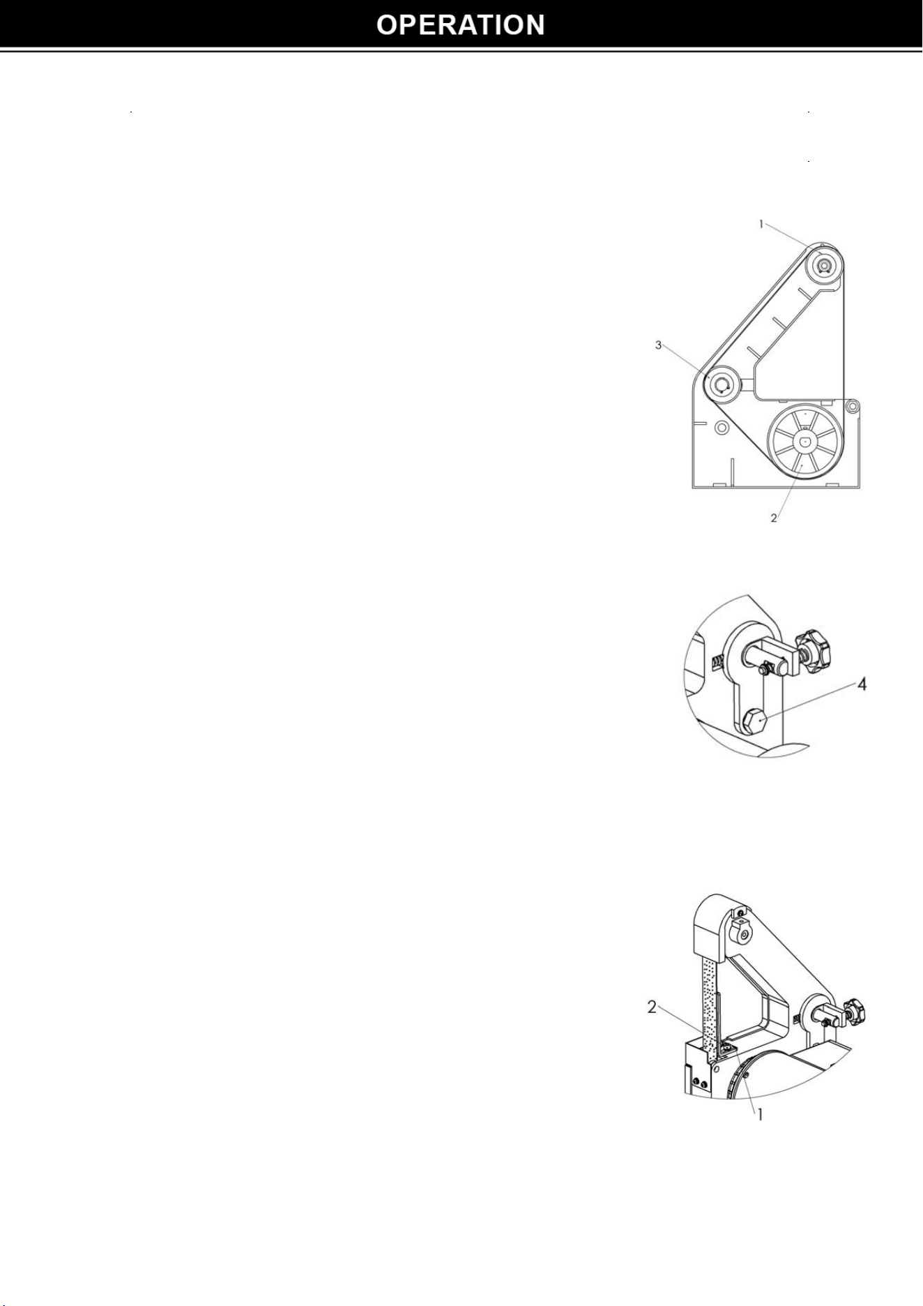
TRACKING
THE BELT (FIG. H)
1. With the belt guard rem
oved and the sander plugged in, flip the
s
witch ON and the OFF.
2. The belt should remain centered on the upper (1), the middle
(3) and the lower
(2) wheels as it turns.
3. If the belt moves
off center, if needs to be adjusted.
4. If the belt moves to the left, s
lightly turn the adjusting bolt (4)
c
ounter clockwise with a hex key. If the belt moves to the right,
s
lightly turn the adjusting bolt clockwise.
5. Disconnect power and test the belt tracking and table
c
learances by hand. Adjust if needed.
NOTE: Turn the knob SLIGHTLY to set proper tracking.
6. Replac
e the belt guard when properly centered and tracking
c
orrectly.
Fig. H
RE
MOVING THE BACKSTOP FOR CONTOUR
SANDING OR POLISHING (FIG. I)
1. Remove the backstop (1) by removing the bolts (2)
and washer (3) from the frame.
2. Replace backstop assembly when finished.
Fig. I
9
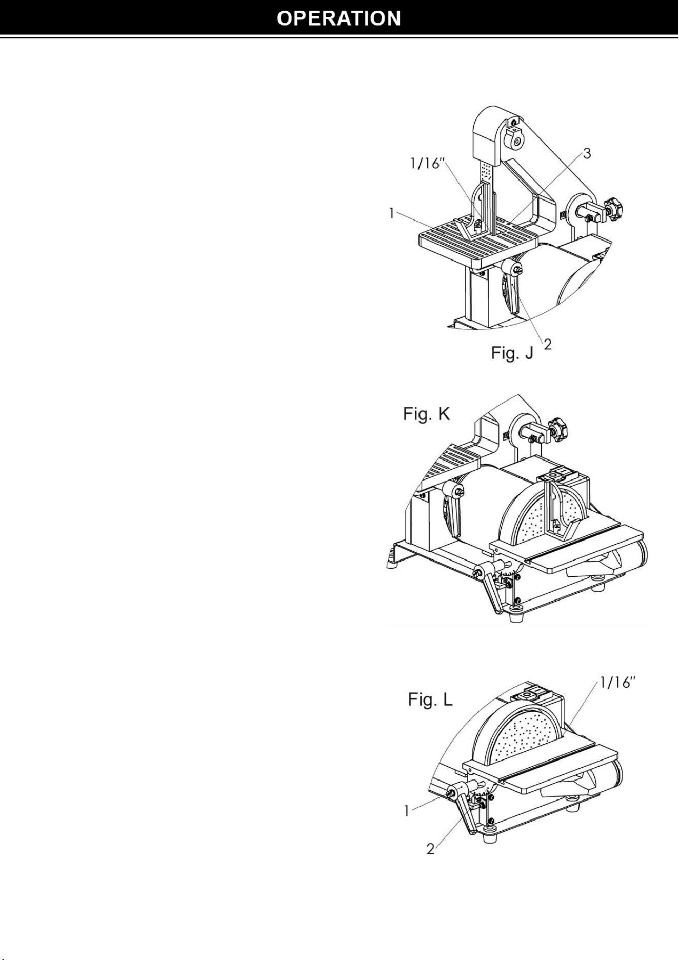
SQUARING THE BELT TABLE (FIG. J)
1. To tilt the table (1) loosen the handle (2).
2. Us
e a combination square to set the table at 90
0
.
3. Adjust fro the 1/16” clearance between the belt
and the table edge.
4. When the belt table is squared to the belt at 90
0
,
lock it into position by tightening the handle (2).
5. Using the wrench supplied, turn the set screw (3)
until the screw touches the frame.
6. The table can be tilted for bevel sanding.
7. Loosen handle (2). Lower the table to the desired
angle.
8. Slide the table toward the belt to set a 1/16” gap
between table and bolt. Lock handle.
SQUARING THE DISC TABLE (FIG. K) To ensure
accurate end sanding, the work table (
1) must be
square to the sanding surface.
1. A
djust the table (1) to be 90
0
perpendicular with the sanding disc (2).
2. Using a combination square, check that the table
is 90
0
to the sanding disc.
3. If the table is not 90
0
to the sanding disc, loosen
the table lock knobs (3), adjust the table,
tighten the knobs and recheck with the square.
ADJUSTING THE DISC TABLE ANGLE (FIG. L)
1. The disc table is adjustable from 0
0
to 45
0
for bevel
work.
2. To adjust the table, loos
en both table lock knobs (1).
Adjust the table to the correct angle. Use the index (2)
located on both sides of the table for an approximate
angle.
3. Set the table edge to the 1/16” from the abrasive disc,
tighten the lock knobs (1) to hold the table angle.
10
S
ANDING OPERATIONS
CAUTION: To avoid personal injury and/or damage to the workpiece, become familiar with the
rotation of the belt and disc sanding surfaces.
The belt sander rotates clockwise, or downward toward the table. The disc sander also rotates
clockwise, downward toward the table on the right side of the disc at all times. Using the left side of
the disc will cause the workpiece to fly up or kickback and could result in injury. Review this
instruction manual for correct operation, adjustment, and basic sanding operations. Apply only
enough pressure to remove material: excessive pressure will reduce sanding efficiency.
WARNING!
After sanding wood and other non-metal materials, clean the area of sawdust and debris before
grinding metal. Sparks could ignite debris and cause a fire.
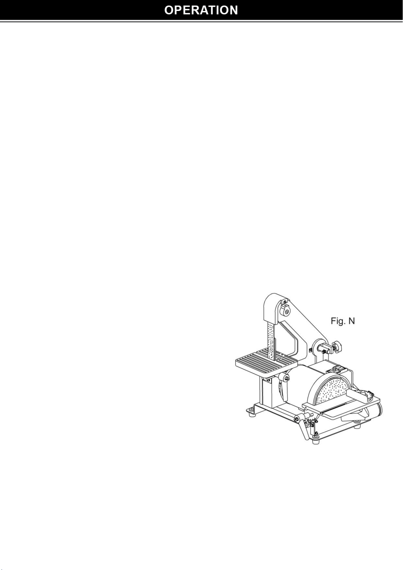
ABRASIVE DISC (FIG. N)
WARNING!
Avoid injury from slips, jams or thrown pieces, make sure all adjustments are made. Review section
ASSEMBLY AND
ADJUSTMENTS for correct disc adjustments.
End sanding and outside curve sanding.
1. Use disc for sanding the ends of small and narr
ow
workpiece and outside curved edges. Always
work on the right side of the disc center
(downward rotation side), holding the workpiece
firmly and applying light pressure against the
sanding disc.
2. The disc moves the fastest and removes more
material at the outer edge.
WARNING!
Us
ing the left side (upward rotation side) of the disc
will cause the workpiece to fly up or kick back and
could result in injury.
ABRASIVE BELT
The abr
asive belt can be used to sand wood, debar metal, or polish plastic and glass. The belt is
most efficient when used with the table. The 1” belt size is convenient for getting into corners
and concave curved edges.
11
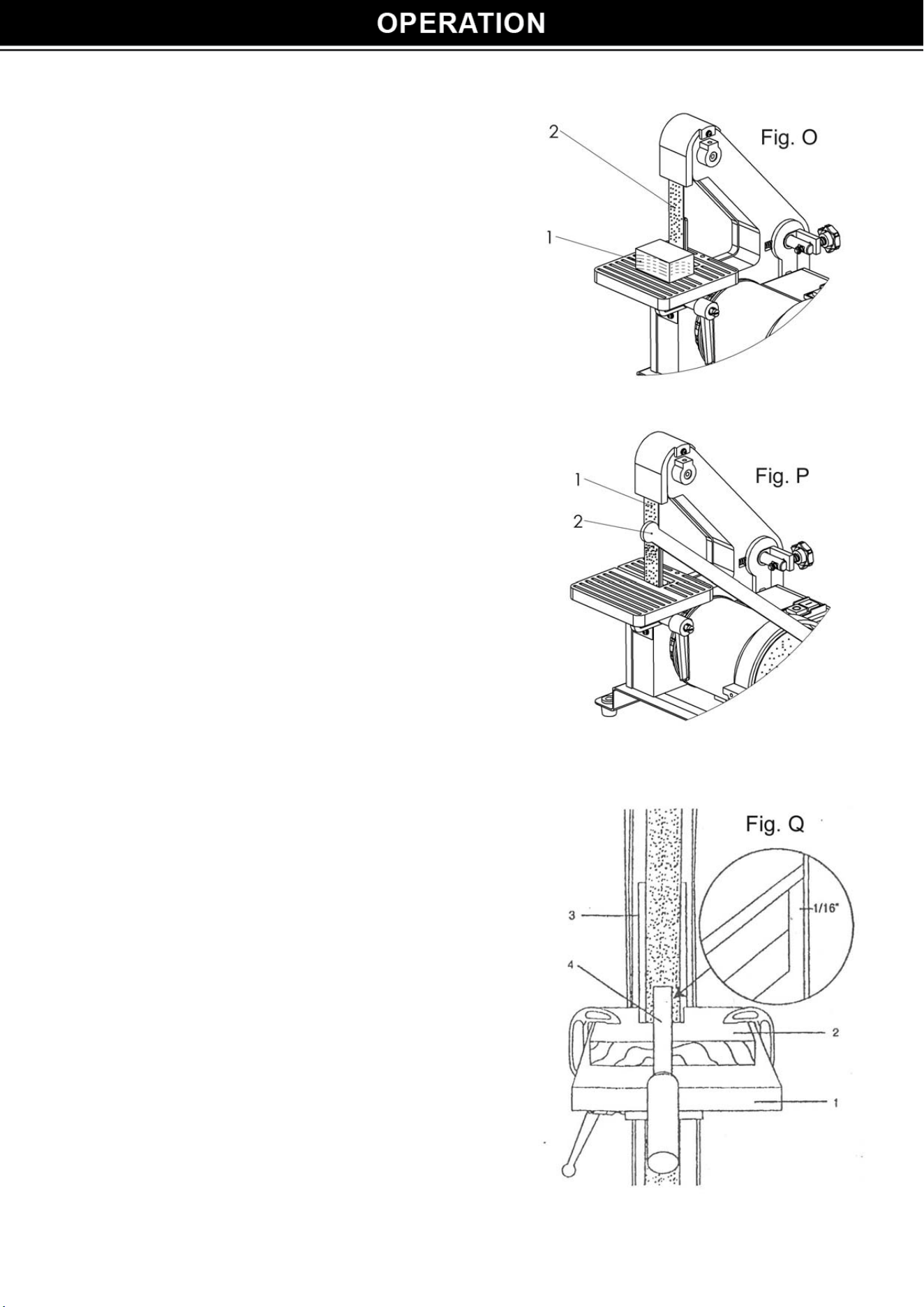
S
traight sanding (Fig. O)
1. Us
e to sand wood, remove metal burrs,
polish plastics and glass (1)
2. Keep the backstop (2) for straight sanding or
grinding operations.
Contour sanding (Fig. P)
1. Remove the bac
kstop to make the abrasive
belt flexible for contour sanding operations (1).
2. Move the workpiece against the belt to follow
contours of the workpiece (2).
S
harpening (Fig. Q)
1. Adjust the metal table (1) to the desired
angle.
2. Make a wooden table-r
est (2) that is the same
width as the metal table. Use the belt sander
to notch the back of the table-rest to match
the angle of the metal table.
3. Place the table-rest (2) on the metal table,
and use the sander to bevel its front edge
until the abrasive belt comes in contact with
its top edge.
4. Position the table-rest 1/16” from the abrasive
belt and clamp it to the metal table.
5. Keep the backstop (3) in place.
6. Hold the tool (4) firmly on the table-rest and
move tools gently toward the abrasive belt
while sharpening.
12

WARNING!
For your safety, turn s
witch OFF, and remove the power cord from the electrical outlet before
adjusting or performing maintenance on your sander.
WARNING!
To avoid electric shock or fire, all repairs to the electrical components should be done by a
qualified service technician.
Before each use check for damaged, missing, or worn parts, check for alignment of moving
parts, binding, improper mounting, or any other c
onditions that red or parts are replaced.
Frequently blew or vacuum dust from all sander parts and motor housing.
WARNING!
A
fter sanding wood or non-metallic material, always clean area of sawdust before grinding or
s
harpening metal workpieces. Sparks could ignite and cause a fire.
LUBRICATION
Ball bearings are grease pac
ked at the factory and require no further lubrication. Use a spray
lubricant to ensure smooth operation on all moving table parts.
SPE
CIFICATIONS
Motor Specs. 120V~60Hz 300W
No-load speed 3,450RPM
Belt Size 1" Width x 30" Diameter
Disc Size
5"
Table Tilt
0-45 Degrees
13
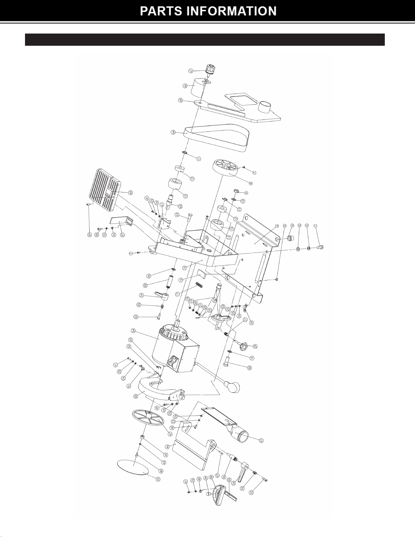
1"X 5" BELT/DISC SANDER PARTS ILLUSTRATION
14

Part# Description Qty Part# Description Qty
1 Hex head bolt M8×18 2 35 Miter guide bar 1
2 Spring washer 8 2 36 Screw 1
3 Falt washer 8 2 37 Round pin 4×20 2
4 Rubber foot 4 38 Miter guide 1
5 Nut M4 2 39 Knob 1
6 Base 1 40 Pointer 1
7 Set screw M5×12 1 41 Screw M4×10 3
8 Driving wheel 1 42 Sanding disc 5” 1
9 Locking nut M10 1 43 Screw M5×10 1
10 Falt washer 10 2 44 Spring washer 5 3
11 Retainer ring 15 2 45 Bushing 1
12 Bearing 6202 2 46 Disc table 1
13 Driven wheel (A) 2 47 Backing disc 1
14 Bolt M6×12 3 48 Screw M4×12 4
15 Frame 1 49 Screw M5×16 2
16 Rubber Pad 1 50 Disc guard 1
17 Spring (C) 1 51 Pointer 1
18 E-ring 4 1 52 Flat key 1
19 Driven wheel (B) 1 53 Retainer Ring 1
20 Flat washer 5 5 54 Motor 1
21 Spring (B) 1 55 Locking nut 1
22 Spring pin 3×18 1 56 Toothed washer 8 1
23 Axle seat 1 57 Backstop 1
24 Set screw M4×16 2 58 Screw M4×12 2
25 Spring washer 4 10 59 Belt table alignment screw M6×16 1
26 Flat washer 4 11 60 Belt table 1
27 Spring (A) 1 61 Lower belt guard 1
28 Clip 1 62 Bolt M8×25 1
29 Belt tension knob 1 63 Pulley axle 1
30 Belt tracking bolt M10×30 1 64 Sanding belt 1”x30” 1
31 Dust chute 1 65 Side cover 1
32 Screw 1 66 Upper belt guard 1
33 Spring 1 67 Knob 1
34 Handle 1
1"x 5" BELT/DISC SANDER PARTS LIST
15