

SKU 240-2972
For questions / comments, technical assistance or repair parts.
Please Call Toll Free at: 1-888-686-1484 (M-F 8am – 6pm)
BELT / DISC SANDER
Operation and Safety Instructions

8
15
16
17
18
19
9
10
11
12
1
2
3
4
5
6
12 1413
7

3
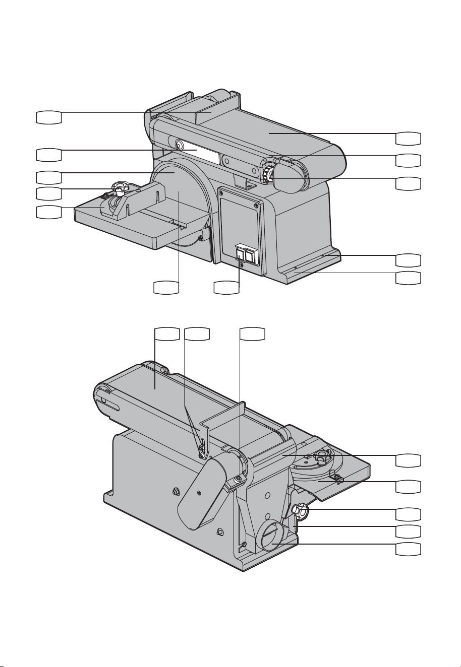
Work support
Belt tension lever
Sanding plate
Miter gauge locking knob
Miter gauge
Sanding disc
On/Off switch
Base
Mounting hole
Belt tracking adjusting knob
Belt bed
Sanding belt
Work support hex screw
Belt bed locking screw
Sanding drum guard
Worktable
Worktable locking knob
Bevel gauge
Dust extraction outlet
* Not all the accessories illustrated or described are included in standard delivery.
Component list
1
2
3
4
5
8
11
14
17
6
9
12
15
18
7
10
13
16
19
45
o
Miter gauge 3
Allen key 1
Sanding belt 1
Sanding disc 1
Use good quality accessories marked with a well-known brand name. Choose the type according to the
work you intend to undertake. Refer to the accessory packaging for further details. Store personnel can
assist you and offer advice.
Accessories

4
WARNING: Some dust created by
power sanding, sawing, grinding,
drilling and other construction activities
contains chemicals known to the state of
California to cause cancer, birth defects or
other reproductive harm. Some examples of
these chemicals are:
• Lead from lead-based paints,
• Crystalline silica from bricks and
cement and other masonry products,
• Arsenic and chromium from
chemically-treated lumber.
Your risk from these exposures varies,
depending on how often you do this type
of work. To reduce your exposure to these
chemical: work in a well ventilated area,
and work with approved safety equipment,
such as those dust masks that are specially
designed to lter out microscopic particles.
WARNING: This product can expose
you to chemicals including lead,
phthalate or bisphenol A which are known
to the State of California to cause cancer,
birth defects or other reproductive harm.
Wash your hands after use. For more
information go to www.P65Warnings.
ca.gov.
General power tool
safety warnings
A. GROUNDING INSTRUCTIONS
1. All grounded, cord-connected tools:
In the event of a malfunction or breakdown,
grounding provides a path of least resistance
for electric current to reduce the risk of
electric shock. This tool is equipped with an
electric cord having an equipment-grounding
conductor and a grounding plug. The plug
must be plugged into a matching outlet that is
properly installed and grounded in accordance
with all local codes and ordinances.
Donotmodifytheplugprovided–ifitwillnott
the outlet, have the proper outlet installed by a
qualiedelectrician.
Improper connection of the equipment-
grounding conductor can result in a risk of
electric shock. The conductor with insulation
having an outer surface that is green with
or without yellow stripes is the equipment-
grounding conductor. If repair or replacement
of the electric cord or plug is necessary, do not
connect the equipment-grounding conductor to
a live terminal.
Checkwithaqualiedelectricianorservice
personnel if the grounding instructions are
not completely understood, or if in doubt as to
whether the tool is properly grounded.
Use only 3-wire extension cords that
have 3-prong grounding plugs and 3-pole
receptacles that accept the tool’s plug.
Repair or replace damaged or worn cord
immediately.
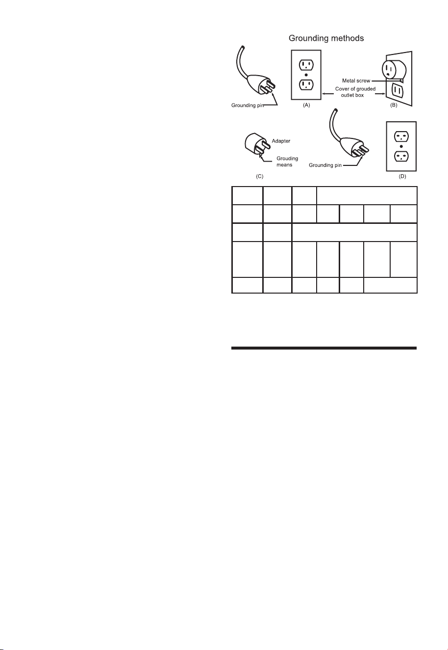
2. Grounded, cord-connected tools intended for
use on a supply circuit having a nominal rating
less than 150V:
This tool is intended for use on a circuit that has
an outlet that looks like the one illustrated in
Sketch A in Figure 1. The tool has a grounding
plug that looks like the plug illustrated in Sketch
A in Figure 1. A temporary adapter, which looks
like the adapter illustrated in Sketches B and C,
may be used to connect this plug to a 2-pole
receptacle as shown in Sketch B if a properly
grounded outlet is not available. The temporary
adapter should be used only until a properly
groundedoutletcanbeinstalledbyaqualied
electrician. The green-colored rigid ear, lug
and the like, extending from the adapter must
be connected to a permanent ground such as
a properly grounded outlet box.
3. Grounded, cord-connected tools intended for
use on a supply circuit having a nominal rating
between 150-250V, inclusive:
This tool is intended for use on a circuit that has
an outlet that looks like the one illustrated in
Sketch D in Figure 1. The tool has a grounding
plug that looks like the plug illustrated in Sketch
D in Figure 1. Make sure the tool is connected
toanoutlethavingthesameconguration
as the plug. No adapter is available or should
be used with this tool. If the tool must be
reconnected for use on a different type of
electric circuit, the reconnection should be
madebyqualiedservicepersonnel;andafter
reconnection, the tool should comply with all
local codes and ordinances.
4. Permanently connected tools:
This tool should be connected to a grounded
metalpermanentwiringsystem;ortoasystem
having an equipment-grounding conductor.

5
B. FOR ALL DOUBLE-INSULATED
TOOLS
1. Replacement parts
When servicing use only identical replacement
parts.
2. Polarized Plugs
To reduce the risk of electric shock, this
equipment has a polarized plug (one blade
iswiderthantheother).Thisplugwilltina
polarized outlet only one way. If the plug does
nottfullyintheoutlet,reversetheplug.Ifitstill
doesnott,contactaqualiedelectricianto
install the proper outlet. Do not change the plug
in any way.
C. FOR ALL TOOLS AS APPLICABLE
1. KEEP GUARDS IN PLACE and in working
order.
2. REMOVE ADJUSTING KEYS AND
WRENCHES. Form habit of checking to see
that keys and adjusting wrenches are removed
from tool before turning it on.
3. KEEP WORK AREA CLEAN. Cluttered
areas and benches invite accidents.
4. DON’T USE IN DANGEROUS
ENVIRONMENT. Don’t use power tools in
damp or wet locations, or expose them to rain.
Keep work area well lighted.
5. KEEP CHILDREN AWAY. All visitors
should be kept safe distance from work area.
6. MAKE WORKSHOP KID PROOF with
padlocks, master switches, or by removing
starter keys.
7. DON’T FORCE TOOL. It will do the job
better and safer at the rate for which it was
designed.
8. USE RIGHT TOOL. Don’t force tool or
attachment to do a job for which it was not
designed.
9. USE PROPER EXTENSION CORD.
Make sure your extension cord is in good
condition. When using an extension cord, be
sure to use one heavy enough to carry the
current your product will draw. An undersized
cord will cause a drop in line voltage resulting
in loss of power and overheating. Table 1
shows the correct size to use depending on
cord length and nameplate ampere rating. If in
doubt, use the next heavier gage. The smaller
the gage number, the heavier the cord.
10. WEAR PROPER APPAREL. Do not
wear loose clothing, gloves, neckties, rings,
bracelets, or other jewelry which may get
caught in moving parts. Nonslip footwear is
recommended. Wear protective hair covering
to contain long hair.
Exception: The reference to gloves may be
omitted from the instructions for a grinder.
11. ALWAYS USE SAFETY GLASSES. Also
use face or dust mask if cutting operation is
dusty. Everyday eyeglasses only have impact
resistant lenses, they are NOT safety glasses.
12. SECURE WORK. Use clamps or a vise to
hold work when practical. It’s safer than using
your hand and it frees both hands to operate
tool.
13. DON’T OVERREACH. Keep proper footing
and balance at all times.
14. MAINTAIN TOOLS WITH CARE. Keep
tools sharp and clean for best and safest
performance. Follow instructions for lubricating
and changing accessories.
15. DISCONNECT TOOLS beforeservicing;
when changing accessories, such as blades,
bits, cutters, and the like.
16. REDUCE THE RISK OF
UNINTENTIONAL STARTING. Make
sure switch is in off position before plugging in.
17. USE RECOMMENDED ACCESSORIES.
Consult the owner’s manual for recommended
accessories. The use of improper accessories
may cause risk of injury to persons.
18. NEVER STAND ON TOOL. Serious injury
could occur if the tool is tipped or if the cutting
tool is unintentionally contacted.
19. CHECK DAMAGED PARTS. Before
further use of the tool, a guard or other part
that is damaged should be carefully checked
to determine that it will operate properly and
perform its intended function – check for
alignment of moving parts, binding of moving
parts, breakage of parts, mounting, and any
other conditions that may affect its operation. A
guard or other part that is damaged should be
properly repaired or replaced.
20. DIRECTION OF FEED. Feed work into a
blade or cutter against the direction of rotation
of the blade or cutter only.
21. NEVER LEAVE TOOL RUNNING
UNATTENDED. TURN POWER OFF.
Don’t leave tool until it comes to a complete
stop.
Exception: The instructions for a bench grinder
need not contain the statement pertaining to
leaving the tool until it comes to a complete
stop.

6
Rating Volts Total length of cord in feet
Ampere
120V
240V
25f t .
50ft.
50f t.
100ft.
10 0 f t.
200 ft.
150 ft.
300 ft.
More
Than
Not
More
Than
AWG
0
6
10
6
10
12
18
18
16
16
16
16
16
14
14
14
12
12
12 16 14 12
Not
Recommended
1. For Your Own Safety Read Instruction Manual
Before Operating Sander
a) Wear eye protection.
b) Support workpiece with miter gage, backstop,
or worktable.
c) Maintain 1/16 inch maximum clearance
between table and sanding belt or disc.
d) Avoid kickback by sanding in accordance with
the directional arrows.
2. Avoid unintentional starting. Make sure you are
prepared to begin work before plugging in the
sander.
3. WARNING! People with pacemakers should
consult their physician(s) before using this
product.Electromagneticeldsinclose
proximity to a heart pacemaker could cause
interference to or failure of the pacemaker.
In addition, people with pacemakers should
adhere to the following:
i. Avoid operating power tools alone.
ii. Properly maintain and inspect all tools before
use to avoid electrical shock.
4. Never leave the sander unattended when it
is plugged into an electrical outlet. Turn off
the tool, and unplug it from its electrical outlet
before leaving.
Additional safety
warning for Sander

7
Voltage
Amps
Belt length
Belt table tilt range
Belt speed
Disc size
Disc speed
Table size
Table tilt range
Weight
Symbols
Technical specifications
Read the manual
Warning
Wear ear protection
Wear eye protection
Wear dust mask
No-load speed
Warning: do not expose to rain or use in damp locations
n
O
120 V~60 Hz
4.3 A
4˝ x 36˝
0
O
/ 90
O
1700 fpm
6 ˝
3600 /min
8-29/32˝ x 6-5/16˝
0-45
O
42 lbs
8
NOTE: Before using the tool, read the
instruction book carefully.
ASSEMBLY
WARNING: Remove the plug from
the socket before carrying out any
adjustment, servicing or maintenance.
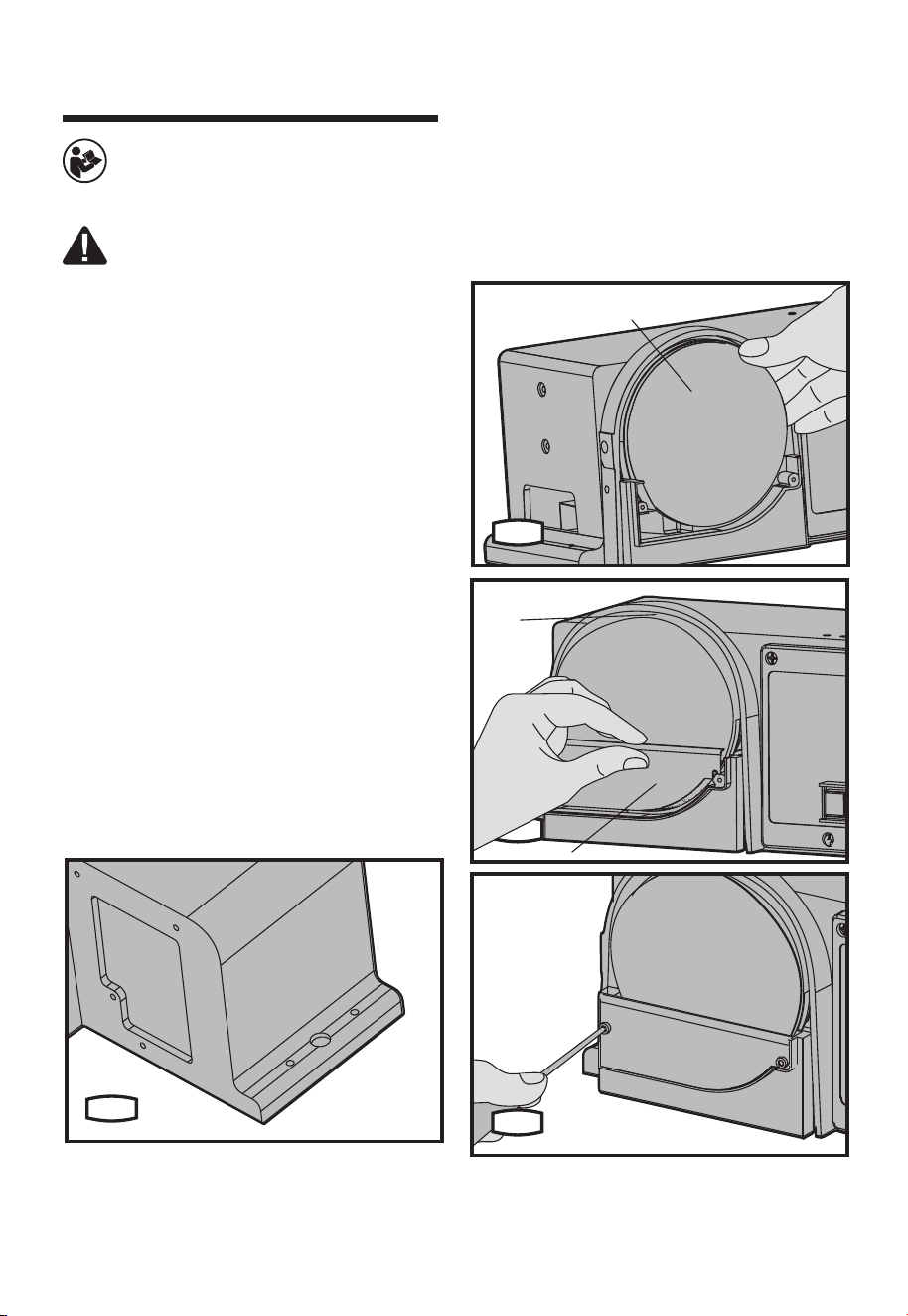
1. MOUNTING THE BELT/DISC SANDER TO
WORKBENCH (SEE FIG.A)
If belt/disc sander is to be used in a permanent
location,itshouldbefastenedsecurelytoarm
supporting surface such as a workbench.
If mounting to a workbench, holes should
be drilled through supporting surface of the
workbench.
1) The unit should be bolted securely using
M8 screws and hex nuts (not provided). Screw
length should be about 1.5” plus the thickness
of the bench top.
2) Locate and mark the holes where belt/disc
sander is to be mounted.
3) Drill 2 holes of 0.4” diameter though
workbench.
4) Place belt/disc sander on workbench aligning
holes drilled in workbench.
5) Insert two M8 screws and tighten hex nuts.
A
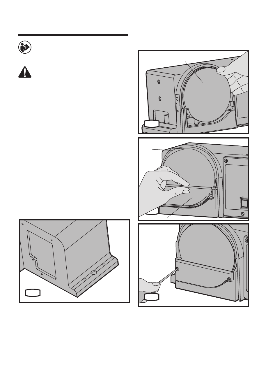
2. ASSEMBLING SANDING DISC AND
GUARD (SEE FIG.B1-B3)
1) Remove the backing from the sanding disc
(6). Align perimeter of disc with sanding plate
(3)andpressdiscrmlyintopositionalltheway
around.
2) Locate disc guard (a) and two M4.2 pan head
screws.
3) Position disc guard against lower 1/3 of disc,
aligning holes.
4) Using a Phillips screwdriver, fasten the pan
head screws securely, applying light pressure to
thread the holes.
6
B1
3
a
B2
B3
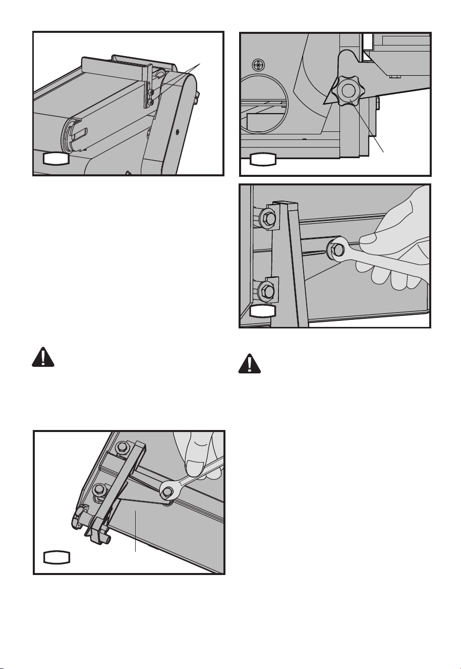
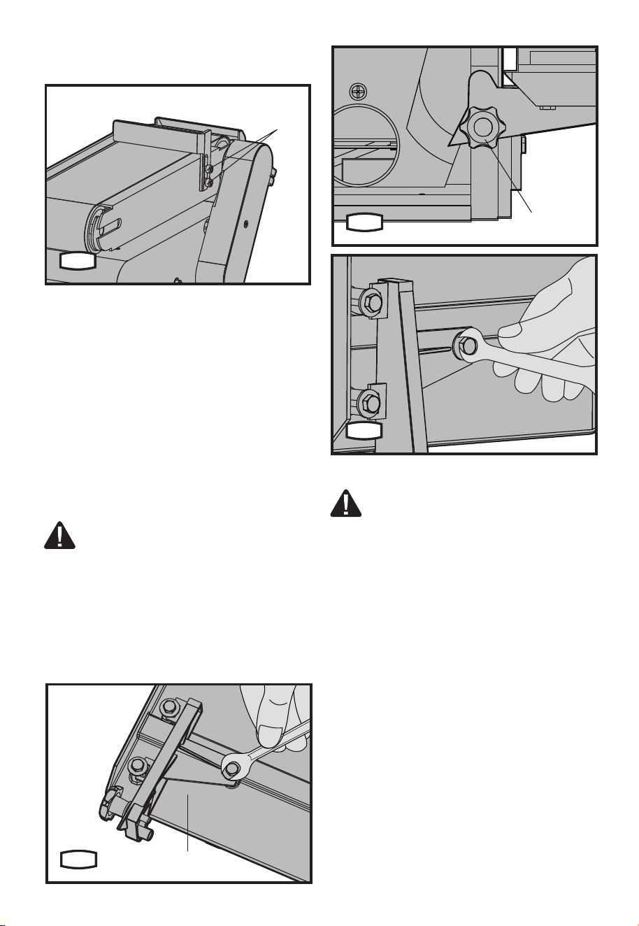
3. INSTALLING WORK SUPPORT (SEE
FIG.C)
1) Adjust the work support hex screw (13) on
side of belt/disc sander by using an allen key.
2) Hold work support in position and fasten.
Operation instructions
9
13
C
4. MOUNTING THE WORKTABLE (SEE FIG.
D1-D3)
1) Position the table support (b) against
worktable and align the holes.
2) Using 3 M6 hex screws, 3 lock washers and
3atwashersfastenthetablesupporttothe
work table.
3) Position the table support in the
corresponding holes on the side of the base.
Ensure that the 0.4” (9.5 mm) diameter index pin
aligns with the upper hole.
4) Place the washer on the end of the worktable
locking knob (17) threaded shaft and insert
shaft through the slot and into the threaded hole
of base.
WARNING: To avoid trapping the work
orngersbetweenthetableandsanding
surface, the table edge should be a minimum of
0.08” (2 mm) from sanding surface.
5) Loosen the 3 hex head screws at bottom
of table support and adjust table as required.
Adjust table as necessary and retighten screws.
b
D1
17
D2
D3
ADJUSTMENT
WARNING: Remove the plug from
the socket before carrying out any
adjustment, servicing or maintenance.
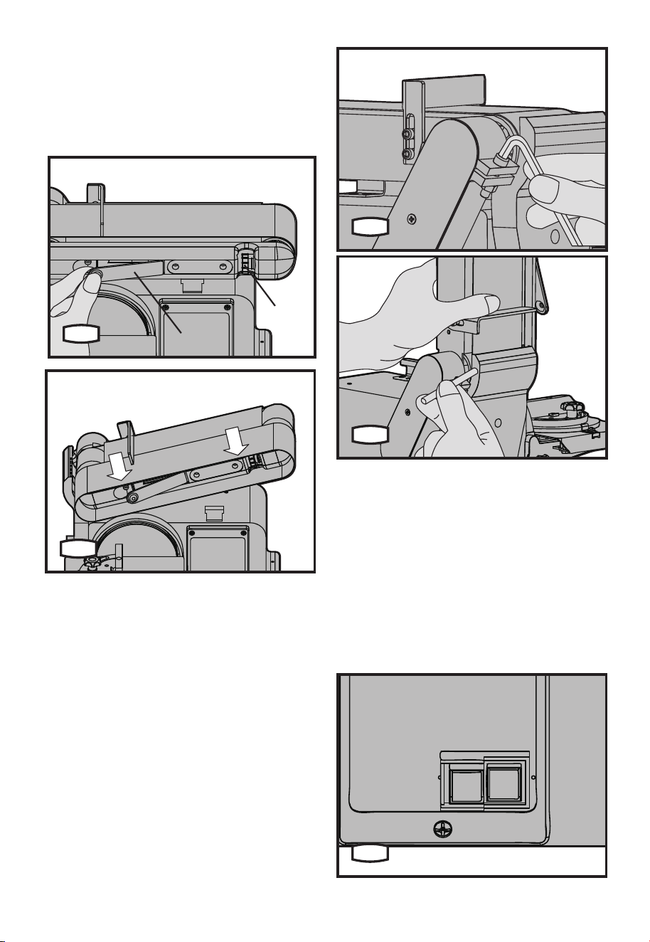
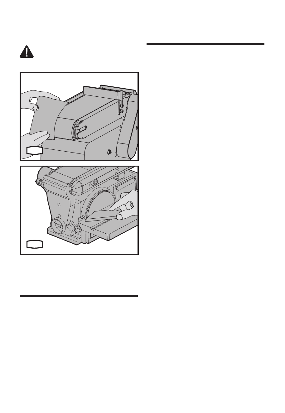
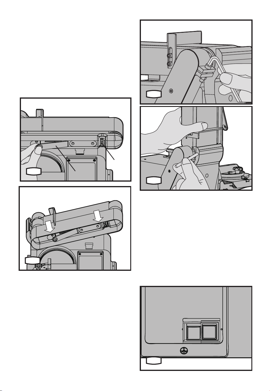
1. INSTALLING/ADJUSTING THE SANDING
BELT (SEE FIG.E1, E2)
On the smooth side of the sanding belt, you will
nda”directionalarrow”.Thesandingbeltmust
run in the direction of this arrow, so that the
splice does not come apart.
1) Pull the belt tension lever (2) to right to
release the belt tension.
2) Place the sanding belt (12) over the drums
with the directional arrow pointing towards the
left hand side. Make sure the belt is centered on
both drums.
3) Slide tension lever to left to apply belt
tension.
4) Tighten the belt bed locking screw (14) when
the bed is in desired position.
5) Plug in the power cord. Turn switch “On” and
immediately “OFF”, noting if the belt tends to
slide off the idler drum or drive drum. If it did not
tend to slide off it is TRACKING properly.
6) If the sanding belt moves toward the disc,
10
turn the tracking adjusting knob (10) clockwise
1/4 turn.
7) If the sanding belt moves away from the disc,
turn the tracking knob counterclockwise 1/4 turn.
8) Turn switch “ON” and immediately “OFF”
noting belt movement. Re-adjust tracking knob
if necessary.
E1
2
10
E2
2. POSITIONING THE BELT BED (SEE FIG.
F1, F2)
The belt bed locking screw locks the belt bed in
a vertical or horizontal position.
To adjust vertical position:
1) Remove work support.
2) Loosen the belt bed locking screw by using
an allen key.
3) Position the belt bed and retighten the hex
locking screw.
F1
F2
OPERATION
1. SWITCH ON/OFF (SEE FIG.G)
To turn the machine on, move the switch to the
“ON” position. To turn it off, move the switch to
the “OFF” position.
To “Lock-off” the machine:
When the machine is not in use and to prevent
unauthorized use, the switch should be locked
in the “OFF” position. To do this, pull the locking
key out of the ON/OFF switch and store the key
in a secure place. With the key removed, the
switch will not operate.
G
11
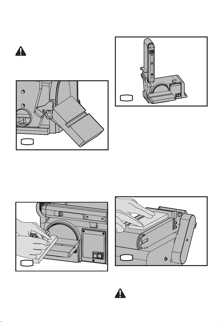
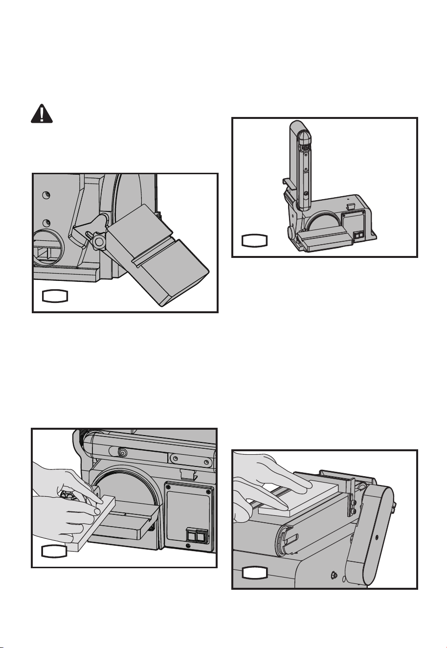
2. BEVEL SANDING (SEE FIG.H)
1) The worktable can be tilted from 0
o
to 45
o
for
bevel sanding.
2) Loosen the worktable locking knob and tilt
the worktable to the desired angle.
3) Retighten the worktable locking knob.
WARNING: To avoid trapping the work
orngersbetweenthetableandsanding
surface, the table should be repositioned on
the table support to retain a minimum of 0.08”
(2 mm) distance between sanding surface and
table.
H
3. MITER SANDING (SEE FIG.I)
1) Use of the miter gauge is recommended for
this operation.
2) Rest the workpiece against the edge of the
miter gauge.
3) Always move the work across the left hand
side of the sanding disc.
4) The table may be tilted for beveled work.
I
4. VERTICAL SANDING (SEE FIG.J)
1) Loosen the belt bed locking screw and raise
the belt bed to the vertical position. Retighten
the belt bed locking screw. (See Fig.F1)
2) Tighten the work support hex screw (13), and
hold the work support in position and fasten.
(See Fig.C)
3) Then your machine can sand vertically. (See
Fig.J)
J
5. SURFACE SANDING ON THE SANDING
BELT (SEE FIG.K)
When checking clearance between the belt
andworksupport,pressthebeltatagainstthe
metal beneath it.
1)Holdtheworkpiecermlywithbothhands,
keepingngersawayfromthesandingbelt.
2) Keep the end butted against the backstop
and move the work evenly across the sanding
belt. Use extra caution when sanding very thin
pieces.
3) When sanding long pieces, remove the work
support.
4) Apply only enough pressure to allow the
sanding belt to remove any material.
K
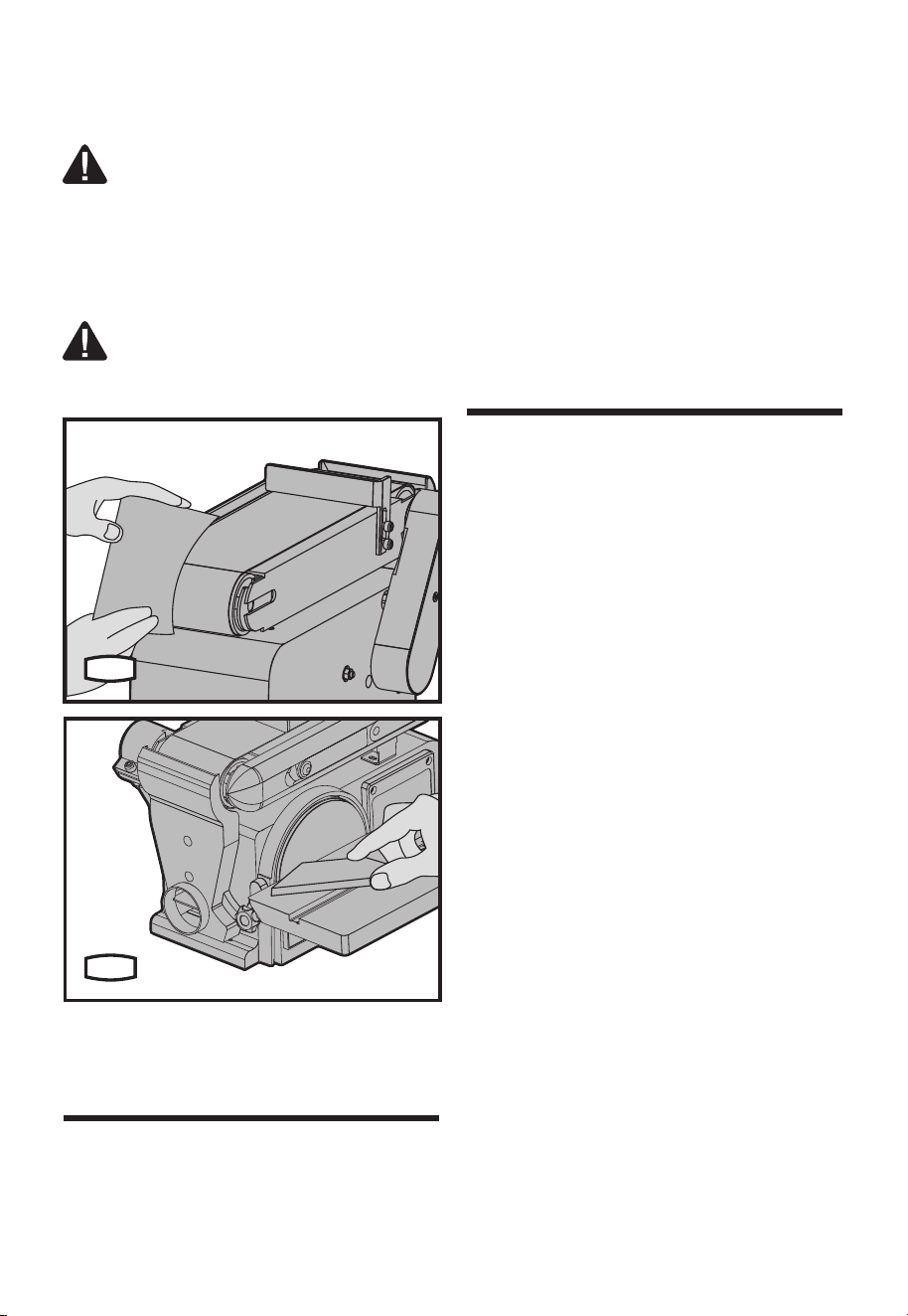
6. SANDING CURVED EDGES
1) Always sand inside curves on idler drum as
shown. (SEE FIG.M1)
WARNING:Never attempt to sand the
ends of a workpiece on the idler drum.
Applying the end of the workpiece to the idler
12
drumcouldcausetheworkpiecetoyupand
result in an injury.
2) Always sand outside curves on the left hand
side of the sanding disc. (SEE FIG.M2)
WARNING: Applying the workpiece to
the right side of the disc could cause
workpiecetoyup(kickback)andresultininjury.
M1
M2
Remove the plug from the socket before carrying
out any adjustment, servicing or maintenance.
There are no user serviceable parts in your power
tool. Never use water or chemical cleaners to
clean your power tool. Wipe clean with a dry cloth.
Always store your power tool in a dry place. Keep
the motor ventilation slots clean. Keep all working
controls free of dust. If you see some sparks
ashingintheventilationslots,thisisnormaland
will not damage your power tool.
If the supply cord is damaged, it must be replaced
by a special cord or assembly available from the
manufacturer or its service agent.
Troubleshooting
Although your new Belt / Disc sander is really very
simple to operate, if you do experience problems,
check the following:
1. Belt / Disc sander
Checkthatthereis“mains”atthesocket;test
with an electrical screwdriver or another electrical
appliance;checktheconnectionsintheplug;
correctandtightenpoorconnections;checkthe
fuse;ifsuspectreplacewithcorrectratingfuse.
2. Wheel wobbles or vibrates
Check that the lock nut is tight. Check that the
wheel is correctly located on the shaft and
locating washer. If excessive pressure has
been used or the wheel has “caught”, it may be
damaged causing it to vibrate. If there is any
evidence that the wheel is damaged, DO NOT
USE, remove it and replace with a new wheel.
Dispose of old wheels sensibly.
Handy hints
Your Belt / Disc sander is useful for wooden work
pieces. However this is not a heavy duty tool and
is designed primarily for light home and hobby
use.
At all times, do not force it or apply excessive
pressure to the wheel.
Try to use the tool rest for supporting and guiding
the workpiece.
Maintain tools with
care
Maintenance and
Troubleshooting

13
Printed in China
Warranty statement
PERFORMAX
®
Belt /Disc SANDER WARRANTY
30-DAY MONEY BACK GUARANTEE:
This PERFORMAX
®
brand power tool carries our 30-Day Money Back Guarantee. If you are not
completelysatisedwithyourPERFORMAX
®
brand power tool for any reason within thirty (30) days
from the date of purchase, return the tool with your original receipt to any MENARDS
®
retail store, and
we will provide you a refund – no questions asked.
2-YEAR LIMITED WARRANTY:
This PERFORMAX
®
brand power tool carries a 2-Year Limited Warranty to the original purchaser.
If, during normal use, this PERFORMAX
®
power tool breaks or fails due to a defect in material or
workmanship within two (2) years from the date of original purchase, simply bring this tool with the
original sales receipt back to your nearest MENARDS
®
retail store. At its discretion, PERFORMAX
®
agrees to have the tool or any defective part(s) repaired or replaced with the same or similar
PERFORMAX
®
product or part free of charge, within the stated warranty period, when returned by the
original purchaser with original sales receipt. Not withstanding the foregoing, this limited warranty does
not cover any damage that has resulted from abuse or misuse of the Merchandise. This warranty: (1)
excludes expendable parts including but not limited to blades, brushes, belts, bits, light bulbs, and/or
batteries;(2)shallbevoidifthistoolisusedforcommercialand/orrentalpurposes;and(3)doesnot
coveranylosses,injuriestopersons/propertyorcosts.Thiswarrantydoesgiveyouspeciclegalrights
and you may have other rights, which vary from state to state. Be careful, tools are dangerous
ifimproperlyusedormaintained.Seller’semployeesarenotqualiedtoadviseyouontheuseofthis
Merchandise. Any oral representation(s) made will not be binding on seller or its employees. The rights
under this limited warranty are to the original purchaser of the Merchandise and may not be transferred
to any subsequent owner. This limited warranty is in lieu of all warranties, expressed or implied including
warrantiesormerchantabilityandtnessforaparticularpurpose.Sellershallnotbeliableforany
special, incidental, or consequential damages. The sole exclusive remedy against the seller will be for
the replacement of any defects as provided herein, as long as the seller is willing or able to replace this
product or is willing to refund the purchase price as provided above. For insurance purposes, seller is
not allowed to demonstrate any of these power tools for you.
For questions / comments, technical assistance or repair parts –
Please Call Toll Free at: 1-888-686-1484 ( (M-F 8am–6pm)
SAVE YOUR RECEIPTS. THIS WARRANTY IS VOID WITHOUT THEM.

SKU 240-2972
Para preguntas / comentarios, asistencia técnica o partes de reparación.
Por favor llame al número telefónico gratuito al: 1-888-686-1484 (Lun-Vie 8am – 6pm)
LIJADORA DE BANDA / DISCO
Instrucciones de operación y seguridad
8
15
16
17
18
19
9
10
11
12
1
2
3
4
5
6
12 1413
7

16
Soporte de trabajo
Palanca de tensión de banda
Placa de lijado
Perilla de bloqueo de calibrador de inglete
Calibrador de esquina
Disco de lijado
2 Interruptor de encendido/apagado
Base
Oricio de montaje
Perilla de ajuste de rastreo de banda
Cama de banda
Banda de lijado
Tornillo hexagonal de soporte de trabajo
Tornillo de bloque de cama de banda
Protección de tambor de lijado
Mesa de trabajo
Perilla de bloqueo de mesa de trabajo
Calibrador de bisel
Salida de extracción de polvo
* No todos los accesorios ilustrados o descritos están incluidos en la entrega estándar.
Lista de componentes
1
2
3
4
5
8
11
14
17
6
9
12
15
18
7
10
13
16
19
45
o
Calibrador de inglete 3
Llave Allen 1
Banda de lijado 1
Disco de lijado 1
Use accesorios de buena calidad marcados con un nombre comercial reconocido. Elija el tipo de
acuerdo con el trabajo que pretende realizar. Consulte el empaque del accesorio respecto a detalles
adicionales. El personal de la tienda lo puede ayudar y ofrecer consejo.
Accesorios

17
ADVERTENCIA: Algún polvo creado
por lijado, aserrado, perforación
eléctricos, y otras actividades de
construcción contiene químicos que se
sabe en el estado de California que causan
cáncer, defectos de nacimiento y otros daños
reproductivos. Algunos ejemplos de estos
químicos son:
• Plomo a partir de pinturas a base de
plomo,
• Sílice cristalino de ladrillos y
cemento y otros productos de
albañilería,
• Arsénico y cromo a partir de madera
tratada químicamente.
Su riesgo a partir de estas exposiciones
varía, dependiendo de qué tan a menudo
realice este tipo de trabajo. Para reducir su
exposición a estos químicos: trabaje en un
área bien ventilada, y trabaje con equipo de
seguridad aprobado, tales como máscaras
de polvo que estén diseñadas especialmente
para ltrar partículas microscópicas.
ADVERTENCIA: Este producto puede
exponerlo a químicos incluyendo
plomo, ftalato o bisfenol A conocidos por
el estado de California que causan cáncer,
defectos de nacimiento u otros daños
reproductivos. Lávese las manos después
del uso. Para mayor información, visite www.
P65Warnings. ca.gov.
Advertencias generales
de seguridad de
herramientas eléctricas
A. INSTRUCCIONES DE CONEXIÓN A
TIERRA
1. Herramientas conectadas con cable, con
conexión a tierra:
En el caso de una falla o descompostura, la
conexión a tierra proporciona una trayectoria
de menor resistencia para la corriente eléctrica
para reducir el riesgo de descarga eléctrica.
Esta herramienta está equipada con un cable
eléctrico que tiene un conductor de conexión
a tierra del equipo y enchufe con conexión
a tierra. El enchufe se debe conectar en un
tomacorriente correspondiente que esté
instalado y conectado a tierra adecuadamente
de acuerdo con todos los códigos y
regulaciones locales.
Nomodiqueelenchufeprovisto–sino
se adapta al tomacorriente, pida que un
electricistacalicadoinstaleeltomacorriente
adecuado.
La conexión incorrecta del conductor de
tierra del equipo puede resultar en un
riesgo de descarga eléctrica. El conductor
conaislamientoquetieneunasupercie
exterior verde con o sin franjas amarillas es
el conductor de conexión a tierra del equipo.
Si es necesaria la reparación o reemplazo
del cable o enchufe eléctrico, no conecte el
conductor de conexión a tierra del equipo a
una terminal con corriente.
Revise con un electricista o personal de
serviciocalicadosinoentiendeporcompleto
las instrucciones de conexión a tierra, o i tiene
dudas si la herramienta está conectada a tierra
adecuadamente.
Sólo use cables de extensión de 3 alambres
que tengan enchufes de conexión a tierra
de 3 clavijas y receptáculos de 3 postes que
acepten el enchufe de la herramienta.
Repare o reemplace el cable dañado o
desgastado de inmediato.
2. Herramientas con cable conectadas a
tierra diseñadas para uso en un circuito de
suministroquetengaunaclasicaciónnominal
menor a 150V:
Esta herramienta está diseñada para uso
en un circuito que tiene un tomacorriente
queseveacomoelilustradoenlaGráca
A en la Figura 1. La herramienta tiene un
enchufe de conexión a tierra que se ve como
el enchufe ilustrado en el Diagrama A en
la Figura 1. Se puede usar un adaptador
temporal, que se parezca al ilustrado en
los Diagramas B y C, para conectar este
enchufe a un receptáculo de 2 polos si no
hay disponible un tomacorriente conectado a
tierra adecuadamente. El adaptador temporal
sólo se debe usar hasta que un electricista
calicadopuedainstalaruntomacorriente
conectado a tierra adecuadamente. La clavija
u oreja rígida de color verde o similares, que
se extienden desde el adaptador se deben
conectar a una tierra permanente tal como
una caja de tomacorriente conectada a tierra
adecuadamente.
3. Herramientas con cable conectadas a
tierra diseñadas para uso en un circuito de
suministroquetengaunaclasicaciónnominal

18
entre 150-250V, incluso:
Esta herramienta está diseñada para uso
en un circuito que tiene un tomacorriente
que se vea como el ilustrado en el Diagrama
D en la Figura 1. La herramienta tiene un
enchufe de conexión a tierra que se ve como
el enchufe ilustrado en el Diagrama D en la
Figura 1. Asegúrese que la herramienta esté
conectada a un tomacorriente que tenga la
mismaconguraciónqueelenchufe.Nohay
un adaptador disponible ni se debe usar con
esta herramienta. Si la herramienta se debe
volver a conectar para uso en un tipo diferente
de circuito eléctrico, la reconexión debe ser
realizadaporpersonaldeserviciocalicado;y
después de la reconexión, la herramienta debe
cumplir con todos los códigos y regulaciones
locales.
4. Herramientas conectadas permanentemente:
Esta herramienta se debe conectar a un
sistema de cableado conectado a tierra de
formapermanente;oaunsistemaquetenga
un conductor de conexión a tierra de equipo.
B. PARA TODAS LAS HERRAMIENTAS
CON AISLAMIENTO DOBLE
1. Partes de reemplazo
Cuando dé servicio, sólo use partes de
reemplazo idénticas.
2. Enchufes polarizados
Para reducir el riesgo de descarga eléctrica,
este equipo tiene un enchufe polarizado (una
clavija es más ancha que la otra). Este enchufe
se conectará a un tomacorriente polarizado de
una sola manera. Si el enchufe no se ajusta
completamente en el tomacorriente, voltee
el enchufe. Si sigue sin conectarse, póngase
encontactoconunelectricistacalicado
para instalar un tomacorriente adecuado. No
cambie el enchufe de ninguna manera.
C. PARA TODAS LAS HERRAMIENTAS
APLICABLES
1. MANTENGA LAS PROTECCIONES
EN SU LUGAR y en buenas condiciones de
operación.
2. RETIRE LAS LLAVES DE AJUSTE Y
LLAVES. Forme el hábito de revisar para
ver que llaves y llaves de tuercas de ajuste se
retiren de la herramienta antes de encenderla.
3. MANTENGA EL ÁREA DE TRABAJO
LIMPIA. Las áreas y bancos abarrotados
provocan accidentes.
4. NO LA USE EN UN AMBIENTE
PELIGROSO. No use herramientas
eléctricas en ubicaciones mojadas o húmedas,
o las exponga a la lluvia. Mantenga el área de
trabajo bien iluminada.
5. MANTENGA LEJOS A LOS NIÑOS.
Todos los visitantes deben mantener una
distancia segura desde el área de trabajo.
6. HAGA EL TALLER A PRUEBA DE
NIÑOS con candados, interruptores
maestros, o retirando las llaves de arranque.
7. NO FUERCE LA HERRAMIENTA. Hará
el trabajo mejor y con más seguridad en la
velocidad para la que está diseñada.
8. USE LA HERRAMIENTA CORRECTA.
No fuerce la herramienta o accesorio para
hacer un trabajo para el que no estén
diseñados.
9. USE EL CABLE DE EXTENSIÓN
ADECUADO. Asegúrese que su cable
de extensión esté en buenas condiciones.
Cuando use un cable de extensión, asegúrese
usarunolosucientementefuertepara
manejar la corriente que requerirá su producto.
Un cable de menor capacidad causará una
caída en el voltaje de línea que resulte en una
pérdida de energía y sobrecalentamiento.
La Tabla 1 muestra el tamaño correcto a
usar dependiendo de la longitud del cable
y la capacidad de amperes de la placa de
identicación.Sitienedudas,useelsiguiente
calibre mayor. Mientras menor es el número de
calibre, el cable es más pesado.
10. UTILICE ROPA ADECUADA. No use
ropa, guantes, corbatas sueltos, anillos,
brazaletes, u otra joyería que puedan
quedar atrapados en las partes móviles. Se
recomienda calzado anti-derrapante. Use
una cubierta de cabello de protección para
contener el cabello largo.
Excepción: La referencia a guantes se
puede omitir de las instrucciones para una
esmeriladora.
11. SIEMPRE USE GAFAS DE
SEGURIDAD. Además use una careta o
máscara para polvo si la operación de corte
produce polvo. Los lentes de uso diario sólo
tienen lentes resistentes a impacto, NO son
gafas de seguridad.
12. ASEGURE EL TRABAJO. Use
abrazaderas o una prensa para sostener el
trabajo cuando resulte práctico. Es más seguro
que usar su mano y mantiene ambas manos
libres para operar la herramienta.
19
13. NO SE ESTIRE EN EXCESO. Mantenga
el apoyo y equilibrio adecuados en todo
momento.
14. DÉ MANTENIMIENTO A LAS
HERRAMIENTAS CON CUIDADO.
Mantengasusherramientasaladasylimpias
para un mejor desempeño y más seguro. Siga
las instrucciones para lubricar y cambiar los
accesorios.
15. DESCONECTE LAS HERRAMIENTAS
antesdedarlesservicio;cuandocambie
los accesorios, tales como aspas, brocas,
cortadores, y similares.
16. REDUZCA EL RIESGO DE
ARRANQUE INADVERTIDO. Asegúrese
que el interruptor esté en posición apagada
antes de conectar la herramienta.
17. USE LOS ACCESORIOS
RECOMENDADOS. Consulte el manual
del propietario respecto a los accesorios
recomendados. El uso de accesorios
incorrectos puede causar el riesgo de lesiones
a las personas.
18. NUNCA SE PARE SOBRE LA
HERRAMIENTA. Podrían ocurrir lesiones
serias su se inclina la herramienta o si se hace
contacto inadvertidamente con la herramienta
de corte.
19. REVISE LAS PARTES DAÑADAS.
Antes del uso adicional de la herramienta,
se debe revisar la protección u otra parte
que esté dañada para determinar que
opere adecuadamente y realice su función
pretendida – revise la alineación de las
partes móviles, atascamiento de partes
móviles, ruptura de partes, montaje, y
cualquier otra condición que pueda afectar su
operación. Una protección u otra parte que
esté dañada se debe reparar o reemplazar
adecuadamente.
20. DIRECCIÓN DE ALIMENTACIÓN.
Alimente el trabajo en la aspa o cortador
contra la dirección de rotación del aspa o
cortador únicamente.
21. NUNCA DEJE LA HERRAMIENTA
EN OPERACIÓN SIN SUPERVISIÓN.
APAGUE LA ENERGÍA.
No deje la herramienta hasta que se pare
completamente.
Excepción: Las instrucciones para una
esmeriladora de banco no necesitan contener
la declaración respecto a dejar la herramienta
hasta que se detenga por completo.
Clasifi-
cación
Voltios Longitud total de cable en pies
Amperes
120 V
240V
25f t.
50ft.
50f t.
100ft.
10 0 f t .
200 ft.
150 ft.
300 ft.
Más de
No más
de
AWG
0
6
10
6
10
12
18
18
16
16
16
16
16
14
14
14
12
12
12 16 14 12 No recomendado
1. Por su propia seguridad, lea el manual de
instrucciones antes de operar la lijadora
a) Use protección para los ojos.
b) Soporte la pieza de trabajo con un calibrador
de inglete, tope, o mesa de trabajo.
c) Mantenga un espacio de 1/16 pulg. máximo
entre la mesa y la banda o disco de lijado.
d) Evite el retroceso por lijado de acuerdo con las
echasdedirección.
2. Evite el arranque inadvertido. Asegúrese de
estar preparado para comenzar a trabajar
antes de conectar la lijadora.
3. ¡ADVERTENCIA! Personas con marcapasos,
deben consultar a sus médicos antes de usar
este producto. Los campos electromagnético
en proximidad cercana a un marcapasos
cardíaco podría causar interferencia o falla
del mismo. Además, las personas con
marcapasos se deben apegar a lo siguiente:
i. Evite operar herramientas eléctricas mientras esté solo.
ii. Dé mantenimiento y revise todas las
herramientas adecuadamente antes del uso
para evitar descargas eléctricas.
4. Nunca deje la lijadora desatendida cuando
esté conectada a un tomacorriente eléctrico.
Apague la herramienta, y desconéctela de su
tomacorriente antes de salir.
Additional safety
warning for Sander

20
Símbolos
Technical specifications
Lea el manual
Advertencia
Use protección para los oídos
Use protección para los ojos
Use máscara de polvo
Velocidad sin carga
Advertencia: No lo exponga a la lluvia o use en ubicaciones húmedas
n
O
120 V~60 Hz
4.3 A
4˝ x 36˝
0
O
/ 90
O
1700 fpm
6 ˝
3600 /min
8-29/32˝ x 6-5/16˝
0-45
O
42 lbs
Voltaje
Amps
Longitud de banda
Rango de inclinación de mesa de banda
Velocidad de banda
Tamaño de disco
Velocidad de disco
Tamaño de mesa
Rango de inclinación de mesa
Peso
21
NOTA: Antes de usar la herramienta, lea
el instructivo cuidadosamente.
ENSAMBLE
ADVERTENCIA: Retire el enchufe del
receptáculo antes de realizar cualquier
ajuste, dar servicio o mantenimiento.
1. MONTAJE DE LIJADORA DE BANDA/
DISCO A BANCO DE TRABAJO (VEA LA
FIG.A)
Si la lijadora de banda/disco se va a usar en
una ubicación permanente, se debe asegurar
rmementeaunasuperciedesoportermetal
como un banco de trabajo.
Si lo instala en un banco de trabajo, se deben
perforaroriciosatravésdelasuperciede
soporte del banco de trabajo.
1)Launidadsedebeatornillarrmemente
con tornillos y tuercas hexagonales M8 (no
incluidos). La longitud del tornillo debe ser
de por lo menos 1.5” más el espesor de la
superciedelbanco.
2)Localiceymarquelosoriciosdondesevaa
instalar la lijadora de banda/disco.
3)Perfore2oriciosde0.4”dediámetroa
través del banco de trabajo.
4) Coloque la lijadora de banda/disco sobre
elbancodetrabajoalineandolosoricios
perforados en el banco de trabajo.
5) Inserte dos tornillos M8 y apriete las tuercas
hexagonales.
A
2. ENSAMBLE DE DISCO DE LIJADO Y
PROTECCIÓN (VEA LA FIG.B1-B3)
1) Retire el respaldo del disco de lijado (6).
Alinee el perímetro del disco con la placa de
lijado(3)ypresioneeldiscormementeen
posición completamente alrededor.
2) Localice la protección del disco (a) y dos
tornillos de cabeza cóncava M4.2.
3) Coloque la protección del disco contra el 1/3
inferiordeldisco,alineandolosoricios.
4) Con un destornillador Phillips, apriete os
tornillos de cabeza cóncava, aplicando presión
ligeraparaenroscarlosoricios.
6
B1
3
a
B2
B3
3. INSTALACIÓN DE SOPORTE DE
TRABAJO (VEA LA FIG.C)
1) Ajuste el tornillo hexagonal del soporte de
trabajo (13) en el lado de la lijadora de banda/
Instrucciones de operación
22
disco con una llave allen.
2) Sostenga el soporte de trabajo en posición y
apriete.
13
C
4. MONTAJE DE LA MESA DE TRABAJO
(VEA LA FIG. D1-D3)
1) Coloque el soporte de la mesa (b) contra la
mesadetrabajoyalineelosoricios.
2) Con los 3 tornillos hexagonales M6, 3 arandelas
de presión y 3 arandelas planas, apriete el soporte
de la mesa a la mesa de trabajo.
3)Coloqueelsoportedemesaenlosoricios
correspondientes sobre el lado de la base.
Asegúrese que el pasador índice de 0.4” (9.5
mm)diámetrosealineeconeloriciosuperior.
4) Coloque la arandela sobre el extremo del eje
roscado de la perilla de bloqueo de la mesa de
trabajo (17) e inserte el eje a través de la ranura
ydentrodeloricioroscadodelabase.
ADVERTENCIA: Para evitar atrapar
el trabajo o los dedos entre la mesa y
lasuperciedelijado,elbordedelamesa
debe estar a un máximo de 0.08” (2 mm) de la
superciedelijado.
5)Aojelos3tornillosdecabezahexagonaldel
soporte de la mesa y ajuste la mesa conforme
se necesite.
Ajuste la mesa conforme sea necesario para
volver a apretar los tornillos.
b
D1
17
D2
D3
AJUSTE
ADVERTENCIA: Retire el enchufe del
receptáculo antes de realizar cualquier
ajuste, dar servicio o mantenimiento.
1. INSTALACIÓN/AJUSTE DE BANDA DE
LIJADO (VEA LA FIG.E1, E2)
En el lado liso de la banda de lijado, encontrará
una”echadedirección”.Labandadelijado
debecorrerendireccióndeestaecha,de
forma que el empalme no se separe.
1) Jale la palanca de tensión de la banda (2) a
la derecha para liberar la tensión de la banda.
2) Coloque la banda de lijado (12) sobre los
tamboresconlaechadedirecciónapuntando
hacia el lado izquierdo. Asegúrese que la banda
esté centrada sobre ambos tambores.
3) Deslice la palanca de tensión a la izquierda
para aplicar tensión a la banda.
4) Apriete el tornillo de bloqueo de la plataforma
de la banda (14) cuando la plataforma esté en la
posición deseada.
5) Conecte el cable eléctrico. “Encienda”
el interruptor y “Apáguelo” de inmediato,
observando si la banda tiende a deslizarse
del tambor de polea intermedia o el tambor de
23
impulso. Si no se deslizó está FUNCIONANDO
adecuadamente.
6) Si la banda de lijado se mueve hacia el disco,
gire la perilla de ajuste de rastreo (10) en
sentido de las manecillas del reloj 1/4 de vuelta.
7) Si la banda de lijado se aleja del disco, gire
la perilla de rastreo en sentido contrario a las
manecillas del reloj 1/4 de vuelta.
8) “Encienda” el interruptor y “Apáguelo” de
inmediato observando el movimiento de la
banda. Vuelva a ajustar la perilla de rastreo si
es necesario.
E1
2
10
E2
2. COLOCACIÓN DE PLATAFORMA DE
BANDA (VEA LA FIG. F1, F2)
El tornillo de bloqueo de la plataforma de banda
asegura la plataforma de banda en posición
vertical u horizontal.
Para ajustar la posición vertical:
1) Retire el soporte del trabajo.
2)Aojeeltornillodebloqueodelaplataforma
de la banda con una llave allen.
3) Coloque la plataforma de la banda y vuelva a
apretar el tornillo de bloqueo hexagonal.
F1
F2
OPERACIÓN
1. ENCENDIDO/APAGADO (VEA LA FIG.G)
Para encender la máquina, mueva el interruptor
a la posición “ON” (encendido). Para apagarla,
mueva el interruptor a la posición “OFF”
(apagado).
Para “Bloquear en apagado” la máquina:
Cuando la máquina no esté en uso y para evitar su
uso no autorizado, el interruptor se debe bloquear
en la posición “OFF” (apagado). Para hacer esto,
jale la llave de bloqueo fuera del interruptor ON/OFF
y guarde la llave en un lugar seguro. Con la llave
retirada, el interruptor no funcionará.
G
24
2. LIJADO DE BISEL (VEA LA FIG.H)
1) La mesa de trabajo se puede inclinar de 0
o
a
45
o
para lijado de bisel.
2)Aojelaperilladebloqueodelamesade
trabajo e inclínela al ángulo deseado.
3) Vuelva a apretar la perilla de bloqueo de la
mesa de trabajo.
ADVERTENCIA: Para evitar atrapar el
trabajo o los dedos entre la mesa y la
superciedelijado,lamesasedebeponer
a colocar sobre el soporte de la mesa para
conservar un máximo de 0.08” (2 mm) de
distanciaentrelasuperciedelijadoylamesa.
H
3. LIJADO DE INGLETE (VEA LA FIG.I)
1) Se recomienda el uso del calibrador de
inglete para esta operación.
2) Repose la pieza de trabajo contra el borde
del calibrador de inglete.
3) Siempre mueva el trabajo a través del lado
izquierdo del disco de lijado.
4) La mesa se puede inclinar para trabajo
biselado.
I
4. LIJADO VERTICAL (VEA LA FIG.J)
1)Aojeeltornillodebloqueodelaplataforma
de la banda y levante la plataforma de la banda
a la posición vertical. Vuelva a apretar el tornillo
de bloqueo de la plataforma de la banda. (Vea
la Fig.F1)
2) Apriete el tornillo hexagonal del soporte de
trabajo (13), y sostenga el soporte de trabajo en
posición y apriete. (Vea la Fig.C)
3) Entonces su máquina puede lijar
verticalmente. (Vea la Fig.J)
J
5. LIJADO DE SUPERFICIE SOBRE BANDA
DE LIJADO (VEA LA FIG.K)
Cuando revise el espacio entre la banda y el
soporte de trabajo, presione la banda plana
contra el metal debajo de ella.
1)Sostengalapiezadetrabajormementecon
ambas manos, manteniendo los dedos alejados
de la banda de lijado.
2) Mantenga el extremo apoyado contra el tope
y mueva el trabajo uniformemente a través de
la banda de lijado. Tenga precaución adicional
cuando lije piezas muy delgadas.
3) Cuando soporte piezas largas, retire el
soporte de trabajo.
4)Apliquesólosucientepresiónparapermitir
que la banda de lijado retire cualquier material.
K
25
6. LIJADO DE BORDES CURVOS
1) Siempre lije dentro de las curvas con el
tambor de polea intermedia como se muestra.
(VEA LA FIG.M1)
ADVERTENCIA: Nunca intente lijar los
extremos de una pieza de trabajo sobre el
tambor de polea intermedia. Aplicar el extremo
de la pieza de trabajo al tambor de la polea
intermedia podría causar que la pieza de trabajo
sea expulsada y resultará en una lesión.
2) Siempre lije las curvas exteriores sobre el lado
izquierdo del disco de lijado. (VEA LA FIG.M2)
ADVERTENCIA: Aplicar la pieza de
trabajo al lado derecho del disco podría
causar que la pieza de trabajo sea expulsada
(retroceso) y resultar en lesiones.
M1
M2
Retire el enchufe del receptáculo antes de realizar
cualquier ajuste, dar servicio o mantenimiento.
No hay partes a las que el usuario pueda dar
servicio en su herramienta eléctrica. Nunca
use agua o limpiadores químicos para limpiar
su herramienta eléctrica. Limpie con una tela
seca. Siempre guarde su herramienta eléctrica
en un lugar seco. Mantenga limpias las ranuras
de ventilación del motor. Mantenga todos los
controles de operación libres de polvo. Si ve
algunas chispas que salen de las ranuras de
ventilación, esto es normal y no dañará su
herramienta eléctrica.
Si el cable de suministro está dañado, se debe
reemplazar con un cable especial o ensamble a
partir del fabricante o su agente de servicio.
Solución de problemas
Aunque su nueva lijadora de banda / disco es
muy simple de operar, si experimenta problemas,
revise lo siguiente:
1. Lijadora de banda / disco
Revise que haya “electricidad” en el
tomacorriente;pruebeconundestornillador
eléctricouotroaparatoeléctrico;reviselas
conexionesenelenchufe;corrijayapriete
conexionesdecientes;reviseelfusible;si
tiene sospecha, reemplace con el fusible de la
clasicacióncorrecta.
2. La rueda oscila o vibra
Revise que la tuerca de bloqueo esté apretada.
Revise que la rueda esté colocada correctamente
sobre el eje y la arandela de localización. Si se
usa presión excesiva o la rueda es “atrapada”,
se puede dañar causando que vibre. Si hay
cualquier evidencia de que la rueda esté dañada,
NO LA USE, retírela y reemplácela por una
nueva rueda. Deseche las ruedas anteriores
adecuadamente.
Consejos útiles
Su lijadora de banda / disco es útil para piezas
de trabajo de madera. Sin embargo, ésta no
es una herramienta de servicio pesado y está
diseñada principalmente para uso doméstico y de
pasatiempos ligero.
En ningún momento fuerce o aplique presión
excesiva a la rueda.
Intente usar el soporte de la herramienta para
apoyar y guiar la pieza de trabajo.
Dé mantenimiento a las
herramientas con cuidado
Mantenimiento y
solución de problemas

26
Printed in China
Declaración de garantía
GARANTÍA DE PERFORMAX
®
7’’ LIJADORA / PULIDORA
GARANTÍA DE DEVOLUCIÓN DE DINERO DE 30 DÍAS:
Esta herramienta eléctrica de la marca PERFORMAX
®
tiene nuestra Garantía de devolución de dinero
de 30 DÍAS. Si no está completamente satisfecho con su herramienta eléctrica marca PERFORMAX
®
por cualquier razón dentro de treinta (30) días desde la fecha de compra, regrese la herramienta con su
recibo original a cualquier tienda al menudeo MENARDS
®
, y le proporcionaremos un reembolso – sin
hacer ninguna pregunta.
GARANTÍA LIMITADA DE 2 AÑOS:
Esta herramienta eléctrica marca PERFORMAX
®
tiene nuestra Garantía Limitada de 2 Años para
el comprador original. Si, durante el uso normal, esta herramienta eléctrica PERFORMAX
®
se
descompone o falla debido a un defecto en material o mano de obra dentro de dos (2) años desde
la fecha de la compra original, simplemente lleve esta herramienta con el recibo de ventas original
de regreso a su tienda al menudeo MENARDS
®
más cercana. A su criterio, PERFORMAX
®
acuerda
que la herramienta o cualquier parte defectuosa se repare o reemplace con el mismo producto o
parte PERFORMAX
®
o similar libre de cargo, dentro del periodo de garantía mencionado, cuando
sea devuelta por el comprador original con el recibo de ventas original. Sin importar lo presente,
esta garantía limitada no cubre ningún daño que haya resultado a partir de abuso o mal uso de
la Mercancía. Esta garantía: (1) excluye partes desechables que incluyen, sin limitarse a aspas,
cepillos,bandasbrocas,focos,y/obaterías;(2)seanularásiestaherramientaseusaparapropósitos
comercialesy/oderenta;y(3)nocubreningunapérdida,lesionesapersonas/dañoalapropiedado
costos.Estagarantíaleotorgaderechoslegalesespecícosypuedetenerotrosderechos,quevarían
de un estado a otro. Tenga cuidado, las herramientas son peligrosas si se usan incorrectamente o se
lesdamantenimientoinadecuado.Losempleadosdelvendedornoestáncalicadosparaaconsejarlo
sobre el uso de esta Mercancía. Cualquier representación verbal realizada no será vinculante para el
vendedor o sus empleados Los derechos bajo esta garantía limitada son para el comprador original de
la Mercancía y no se pueden transferir a ningún propietario subsecuente. Esta garantía limitada está en
lugar de todas las garantías, expresas o implícitas incluyendo garantías o comerciabilidad o adecuación
para un propósito particular. El vendedor no será responsable por cualquier daño especial, incidental o
en consecuencia. El único remedio exclusivo contra el vendedor será el reemplazo de cualquier defecto
como se indica en el presente, siempre y cuando el vendedor desee o pueda reemplazar este producto
o desee reembolsar el precio de compra como se indica anteriormente. Para propósitos de seguro, no
se permite que el vendedor demuestre ninguna de estas herramientas eléctricas para usted.
Para preguntas / comentarios, asistencia técnica o partes de reparación -
Por favor llame al número telefónico gratuito al: 1-888-686-1484 ( (Lunes-Viernes 8am–6pm)
CONSERVE SUS RECIBOS. ESTA GARANTÍA ES NULA SIN ELLOS.