Loading ...
Loading ...
Loading ...
Page 12
The xed base is designed with a ne-
adjustment system. When the bit is lowered
to the approximate position desired (coarse
setting), the system can then be micro-
adjusted to the precise depth.
FIG. 6
Fine-
adjustment
dial
Depth-indicator
ring
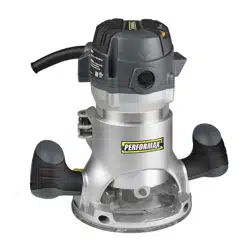
COARSE ADJUSTMENT:
Depressing the coarse-adjustment button
allows you to quickly lower or raise the
cutter bit to an approximate depth setting.
FINE ADJUSTMENTS:
NOTICE: Be sure that the worm gear
system is engaged before making ne
adjustments. Test it by rotating the ne-
adjustment dial to check that the bit
lowers and raises. If it does not, press in
the coarse-adjustment button and turn
the ne-adjustment dial until the gears
engage, then reset zero “0” on the depth-
indicator ring.
The depth-indicator ring located on the
ne-adjustment dial is marked in 1/64”
increments. Turning the ne-adjustment dial
clockwise 180º (1/2 turn), lowers the cutter
bit 1/16”. One full turn clockwise 360° (zero
“0” to zero “0”) lowers the bit 1/8”.
The system allows a maximum of 17 full 360º
revolutions clockwise, to lower the cutter bit
a total of 2 1/8 inch (54mm).
The depth-indicator ring may be reset to zero
“0” without moving the ne-adjustment dial.
This allows the user to begin adjustments
from any reference point desired.
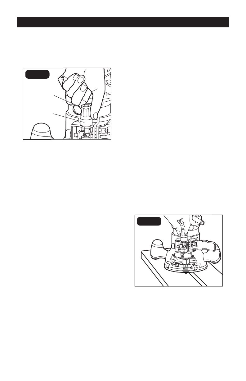
ADJUSTING DEPTH (FIG. 7)
1. Disconnect the plug from the power
supply.
2. Place the router on a at surface with
the back of the xed base facing you.
Open the motor clamp.
3. With the cutter bit already installed,
press in the coarse-adjustment button
and lower the motor into the base until
the cutter bit is close to the at surface
on which the base is sitting. Turn the
ne-adjustment dial until the cutter bit
“just” touches the at surface on which
the base is sitting. Then lock the motor
clamp.
4. Place the router on two level pieces of
wood, positioned so that the cutter bit
can be lowered below the sub-base
(FIG. 7).
5. Turn the ne-adjustment dial clockwise
to lower the bit to the desired depth of
cut. Turn the dial counterclockwise to
raise the cutter bit.
6. Once the depth of cut is set, close the
motor clamp securely.
FIG. 7
DEEP CUTS
The proper cutting depth for each pass,
is always determined by the material, the
cutter bit size and type, and the power of
the motor.
ASSEMBLY
Loading ...
Loading ...
Loading ...