
Loading ...
Loading ...
Loading ...
Page 9
WARNING:
If any part is broken
or missing, DO NOT attempt to plug in the
power cord or operate the tool until the
broken or missing part is replaced. Failure to
do so could result in possibly serious injury.
WARNING:
Do not attempt to
modify this tool or create accessories not
recommended for use with this tool. Any
such alteration or modication is misuse
and could result in a hazardous condition
leading to possible serious injury.
WARNING:
Your tool should
never be connected to the power source
when you are assembling parts, making
adjustments, installing or removing
blades, cleaning, or when it is not in
use. Disconnecting the tool will prevent
accidental starting, which could cause
serious personal injury.
CONTENTS
Router, xed base, collets, collet wrench,
dust-extraction adaptor and instruction
manual.
UNPACKING
1. Carefully remove the tool and any
accessories from the carton. Make sure
that all items listed in the packing list are
included.
2. Inspect the tool carefully to make sure
that no breakage or damage occurred
during shipping.
3. Do not discard the packing material
until you have carefully inspected and
satisfactorily operated the tool.
SELECTING THE COLLET
This router comes with 1/2”collet and 1/4”
collet sleeve that accept cutter bits with 1/2”
and 1/4” shanks, respectively. The 1/2” collet
is installed on the tool; the 1/4” collet sleeve
can be installed inside of the 1/2” collet.
INSTALLING THE 1/4” COLLET
SLEEVE (FIG. 1-2)
1. Disconnect the plug from the power
supply.
2. Remove the router motor from the
base; refer to the section “REMOVING
MOTOR FROM BASE”.
3. Set the router motor upside down on its
top cap, with the collet pointing up.
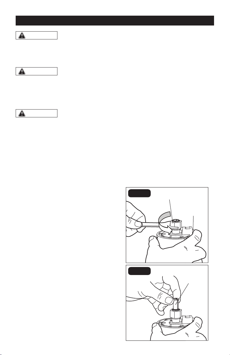
4. Press the spindle-lock button to engage
and lock the spindle shaft and collet nut
(FIG. 1).
5. Place the collet wrench on the collet nut
and turn it counterclockwise to loosen
the collet nut slightly to accept the
cutter bit shank.
6. Insert the 1/4” collet sleeve into the 1/2”
collet assembly as far as it will go (FIG. 2).
7. With the 1/4” collet sleeve inserted
and the spindle-lock button pressed
in to engage the shaft, place the collet
wrench on the collet nut and turn it
clockwise until the 1/4” collet sleeve is
tightened on the 1/2” collet nut.
FIG. 1
Collet nut
Spindle-
lock button
FIG. 2
1/4” Collet
ASSEMBLY
Loading ...
Loading ...
Loading ...