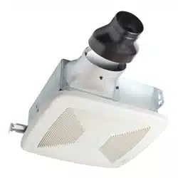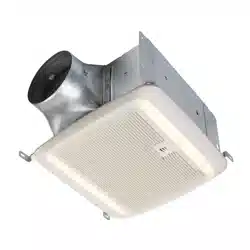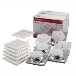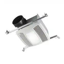
QTXEN110HFLT
Humidity Sensing
Fan/Fluorescent Light/
Night Light
READ AND SAVE THESE INSTRUCTIONS
WARNING
TO REDUCE THE RISK OF FIRE, ELECTRIC SHOCK, OR INJURY TO PER-
SONS, OBSERVE THE FOLLOWING:
1. Use this unit only in the manner intended by the manufacturer. If you
have questions, contact the manufacturer at the address or telephone
number listed in the warranty.
2. Before servicing or cleaning unit, switch power off at service panel
and lock the service disconnecting means to prevent power from being
switched on accidentally. When the service disconnecting means cannot
be locked, securely fasten a prominent warning device, such as a tag, to
the service panel.
3. Installation work and electrical wiring must be done by a qualified per-
son(s) in accordance with all applicable codes and standards, including
fire-rated construction codes and standards.
4. Sufficient air is needed for proper combustion and exhausting of gases
through the flue (chimney) of fuel burning equipment to prevent back-
drafting. Follow the heating equipment manufacturer’s guideline and
safety standards such as those published by the National Fire Protection
Association (NFPA), and the American Society for Heating, Refrigeration
and Air Conditioning Engineers (ASHRAE), and the local code authorities.
5. When cutting or drilling into wall or ceiling, do not damage electrical
wiring and other hidden utilities.
6. Ducted fans must always be vented to the outdoors.
7. Acceptable for use over a tub or shower when connected to a GFCI (Ground
Fault Circuit Interrupter) - protected branch circuit.
8. This unit must be grounded.
CAUTION
1. For general ventilating use only. Do not use to exhaust hazardous or explosive
materials and vapors.
2. This product is designed for installation in ceilings up to a 12/12 pitch (45
degree angle). Duct connector must point up. DO NOT MOUNT THIS PROD-
UCT IN A WALL.
3. To avoid motor bearing damage and noisy and/or unbalanced impellers, keep
drywall spray, construction dust, etc. off power unit.
4. Please read specification label on product for further information and
requirements.
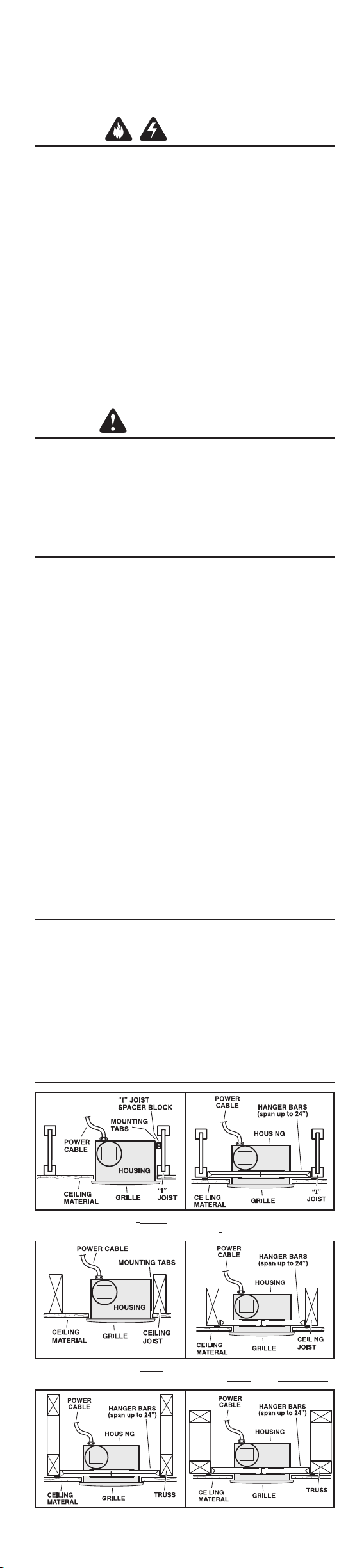
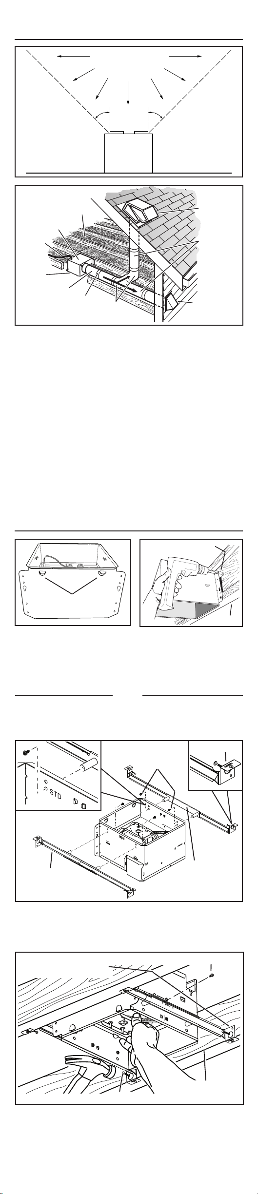
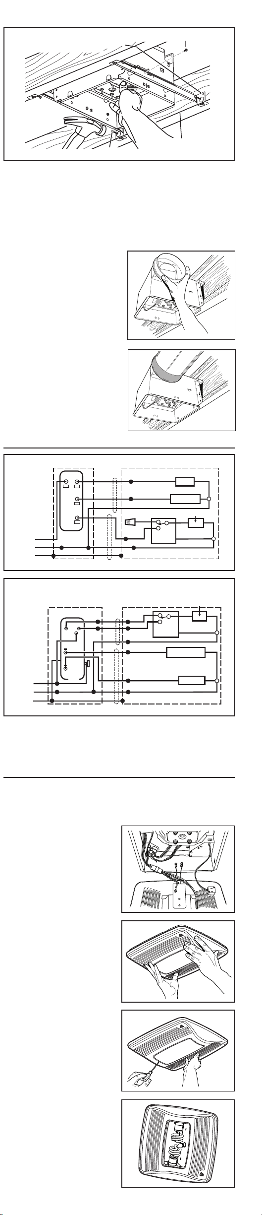
TYPICAL INSTALLATIONS
PLAN THE INSTALLATION
INSTALL HOUSING & DUCT
1a. Mount housing to joist or I-joist.
Use a pliers to bend housing TABS out to 90
0
. Hold housing in place so that
the housing tabs contact the bottom of the joist. The housing mounts with
four (4) screws or nails. Screw or nail housing to joist through lowest holes
in each mounting flange, then through highest holes. NOTE: Mounting to
I-JOIST (shown) requires use of SPACERS (included) between the highest
hole of each mounting flange and the I-joist.
TABS
SPACER
(use for mounting to I-Joist)
I-JOIST
*Purchase
separately.
INSULATION*
(Place around and
over Fan Housing.)
ROOF CAP*
(with built-in
damper)
FAN
HOUSING
POWER
CABLE*
6-IN. ROUND
DUCT*
6-IN.
ROUND
ELBOWS*
Seal gaps
around
Housing.
Seal duct
joints with
tape.
OR
Keep duct
runs short.
WALL CAP*
(with built-in
damper)
OR
1b. Mount housing anywhere between trusses, joists, or I-joists using hanger bars.
Sliding hanger bars are provided to allow for accurate positioning of housing
anywhere between framing. They can be used on all types of framing (I-joist,
standard joist, and truss construction) and span up to 24”.
HANGER
BAR (4)
SCREWS (4)
MOUNTING
CHANNEL (2)
TAB
Housing mounted to I-joists.
Housing mounted anywhere be-
tween trusses using hanger bars.
Housing mounted anywhere be-
tween I-joists using hanger bars.
Housing mounted to joists.
Housing mounted anywhere
between joists using hanger bars.
Housing mounted anywhere be-
tween trusses using hanger bars.
Cooking
Equipment
Floor
COOKING AREA
Do not install above or
inside this area.
45
o
45
o
NOT FOR USE IN
A COOKING AREA.
Attach the MOUNTING CHANNELS to the housing using the screws
supplied. Make sure TABS face “up” as shown. Use the set of channel
mounting holes (marked “STD”) to mount the housing flush with the
bottom of the drywall. Use the other set of holes (not marked) to mount
the housing flush with the top of the drywall.
99045939A
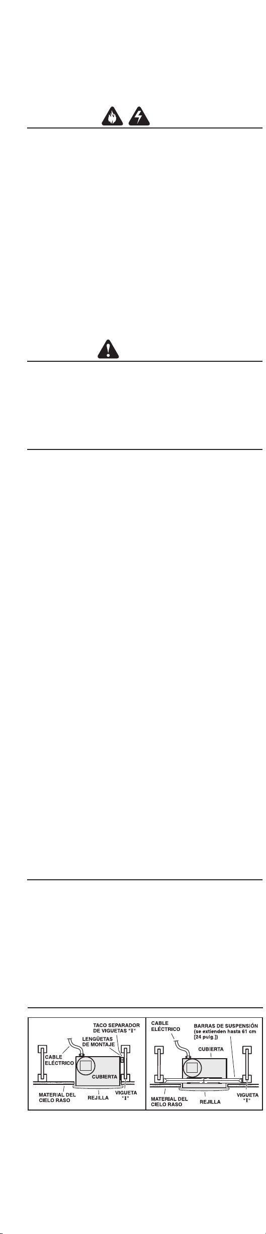
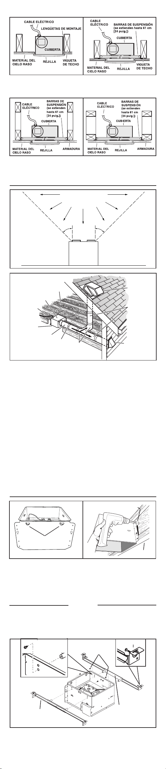
1. Connect electrical wiring.
Run 120 VAC house wiring to installation location. Use proper UL ap-
proved connector to secure house wiring to wiring plate. Connect wires
as shown in wiring diagrams.
CONNECT WIRING
2. Attach damper/duct
connector.
Snap damper / duct
connector onto hous-
ing. Make sure con-
nector is flush with top
of housing and damper
flap falls closed.
3. Install 6-inch round
ductwork.
Connect 6-inch round
ductwork to damper /
duct connector. Run
ductwork to a roof cap
or wall cap. Tape all
ductwork connections
to make them secure
and air tight.
INSTALL GRILLE
1. Finish ceiling.
Install ceiling material. Cut out around housing.
2. Plug in wiring.
Plug wiring into the proper receptacles.
3. Attach grille to
housing.
Squeeze grille springs
and insert them into
slots on each side of
housing.
4. Push grille against
ceiling.
Extend hanger bars to the width of the framing.
Hold ventilator in place with the hanger bar tabs wrapping around the bottom
edge of the framing.
Nail ventilator to framing or fasten with screws (not provided) through
holes near nails.
* To ensure a noise-free mount: Secure hanger bars together with screws or
use a pliers to crimp mounting channels tightly around hanger bars.
*
SCREW (2)
HOLE FOR OPTIONAL
SCREW MOUNTING (4)
NAIL (4)
BOTTOM EDGE
OF FRAMING
Register this product at www.broan.com/
register. For Warranty Statement, or to
order Service Parts: go to nutone.com and
type the Model in the “Model Search” field
at the top of the page. Broan, 926 W. State
Street, Hartford, WI 53027 800-637-1453
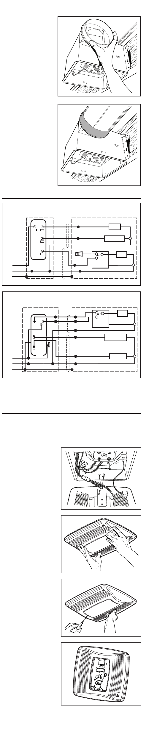
5. Remove light lens.
Carefully insert a
small flat-blade
screwdriver
between grille and
lens. Pry lens out.
6. Install light bulbs.
Fluorescent bulbs
supplied. Purchase
a 4W incandescent
night-light bulb. In-
sert bulbs into their
sockets. Replace
lens.
OPERATION
The humidity control and fan can be operated separately. Do not use a dimmer
switch to operate the humidity control or light. See “Connect Wiring” for details.
SENSOR OPERATION
This humidity-sensing
fan responds to: (a) rapid to moderate humidity increases and
(b) humidity above a 50%-80% relative humidity (RH) set-point. (a) and (b) are set
with “HUMIDITY” adjustment. Fan may occasionally turn on when environmental
conditions change. If the fan continuously responds to changing environmental
conditions, “HUMIDITY” adjustment may be required (see section below).
STATUS INDICATOR
This indicator can only be seen by looking directly at it. Normal mode is 5-seconds
on and off. If it blinks rapidly for 5-seconds and then off, check sensor connections
on grille and fan housing.
MANUAL ON WITH TIMED OFF
For odor or vapor control, the fan can be energized by cycling its wall-mounted switch
if one is installed. Once the fan has been turned on in this manner, it will remain on
for the set “MINUTES” period. To manually energize the fan:
1. Go to Step 2 if switch is already on; otherwise, turn switch on for more than 1 second.
2. Switch off for less than 1 second.
3. Switch back on and fan will turn on.
HUMIDITY ADJUSTMENT
“HUMIDITY” has been factory set for most shower applications. If the fan is in a tub
area or is used for dampness control, the “HUMIDITY” may need to be decreased
toward 50% RH. If the control is responding too often to changing environmental
conditions, adjustment toward 80% RH may be required. To adjust the “HUMIDITY”:
1. Turn power off at electrical service panel.
2. Through the grille, locate the “HUMIDITY” screwdriver slot.
3. Using a small, flat-blade screwdriver, carefully rotate “HUMIDITY” adjustment
toward 50 or 80.
4. Turn power on and check operation by turning on shower or other humidity
source until fan turns on.
5. Repeat above steps if necessary.
CLEANING & MAINTENANCE
For quiet and efficient operation, long life, and attractive appearance - lower or remove
grille and vacuum interior of unit with a dusting brush attachment.
The motor is permanently lubricated and never needs oiling. If the motor bearings
are making excessive or unusual noises, replace the motor/blower wheel assembly.
SENSOR CLEANING
The humidity sensor is mounted in the grille. The sensor will operate most reliably
when cleaned occasionally as follows:
1. Disconnect power at service entrance.
2. Remove the grille. Use a dry dustcloth, clean toothbrush, or lightly vacuum to
clean sensor and grille. DO NOT USE ABRASIVE CLOTH, STEEL WOOL PADS,
OR SCOURING POWDERS.
3. DO NOT USE cleaning sprays, solvents, or water on or near the sensor!
1. Choose the installation location.
The location of your humidity sensing fan is very important. Use the following
guidelines for best operation:
• Locate unit above (GFCI protected circuit required) or within 5 feet of shower
head.
• Locate unit away from heating or cooling sources which can affect humidity levels.
• Do not locate near window. Unit may respond to the outdoor humidity level.
• Unit must be installed in ceiling to properly sense moisture.
• Locate unit only on flat ceilings up to 12 feet high for proper sensing.
• The ducting from this fan to the outside of the building has a strong effect on
the air flow, noise and energy use of the fan. Use the shortest, straightest duct
routing possible for best performance, and avoid installing the fan with smaller
ducts than recommended. Insulation around the ducts can reduce energy loss
and inhibit mold growth. Fans installed with existing ducts may not achieve their
rated airflow.
• Use a roof cap or wall cap that has a built-in damper to reduce backdrafts.
• Plan to supply the unit with proper line voltage and appropriate power cable.
2. Plan the wiring.
• Plan to supply the unit with proper line voltage and appropriate power cable.
Power cable should be routed to the switch box first and then to the unit (See
“CONNECT WIRING” on page 3).
• Do not operate this unit with a speed controlDamage to the sensor unit will result.
• Light or night-light may be installed with a wall-mounted motion control.
MODEL 66V, 66W
3-FUNCTION CONTROL (PURCHASE SEPARATELY)
LIGHT
(ON/OFF)
COM
NIGHT LIGHT
(ON/OFF)
FAN
(AUTO/OFF)
120
VAC
LINE
IN
SWITCH BOX
WHT
GRD
BLK
BLU
RED
WHT
UNIT
ORG
BLK
WHT
GRD
BLK
RED
LIGHT
NIGHT LIGHT
WHT
WHT
BLK
WHT
BRN
HUMIDITY
CONTROL
FAN
MODEL 77DV, 77DW
4-FUNCTION CONTROL (PURCHASE SEPARATELY)
FAN
(ON/OFF/AUTO)
120
VAC
LINE
IN
SWITCH BOX
GRD
RED
RED
BLU
UNIT
RED
BLU
WHT
GRD
WHT
BLK
BLK
RED
WHT
BLK
NIGHT LIGHT
(ON/OFF)
LIGHT
(ON/OFF)
COM
COM
BLK
BLK
WHT
ORG
WHT
BLK
WHT
BRN
HUMIDITY
CONTROL
FAN
WHT
NIGHT LIGHT
LIGHT
WIRING OPTION #1
WIRING OPTION #2 - Fan can be turned ON, OFF, or set to operate automatically.
QTXEN110HFLT
Humidity Sensing
Fan/Fluorescent Light/
Night Light
READ AND SAVE THESE INSTRUCTIONS
WARNING
TO REDUCE THE RISK OF FIRE, ELECTRIC SHOCK, OR INJURY TO PER-
SONS, OBSERVE THE FOLLOWING:
1. Use this unit only in the manner intended by the manufacturer. If you
have questions, contact the manufacturer at the address or telephone
number listed in the warranty.
2. Before servicing or cleaning unit, switch power off at service panel
and lock the service disconnecting means to prevent power from being
switched on accidentally. When the service disconnecting means cannot
be locked, securely fasten a prominent warning device, such as a tag, to
the service panel.
3. Installation work and electrical wiring must be done by a qualified per-
son(s) in accordance with all applicable codes and standards, including
fire-rated construction codes and standards.
4. Sufficient air is needed for proper combustion and exhausting of gases
through the flue (chimney) of fuel burning equipment to prevent back-
drafting. Follow the heating equipment manufacturer’s guideline and
safety standards such as those published by the National Fire Protection
Association (NFPA), and the American Society for Heating, Refrigeration
and Air Conditioning Engineers (ASHRAE), and the local code authorities.
5. When cutting or drilling into wall or ceiling, do not damage electrical
wiring and other hidden utilities.
6. Ducted fans must always be vented to the outdoors.
7. Acceptable for use over a tub or shower when connected to a GFCI (Ground
Fault Circuit Interrupter) - protected branch circuit.
8. This unit must be grounded.
CAUTION
1. For general ventilating use only. Do not use to exhaust hazardous or explosive
materials and vapors.
2. This product is designed for installation in ceilings up to a 12/12 pitch (45
degree angle). Duct connector must point up. DO NOT MOUNT THIS PROD-
UCT IN A WALL.
3. To avoid motor bearing damage and noisy and/or unbalanced impellers, keep
drywall spray, construction dust, etc. off power unit.
4. Please read specification label on product for further information and
requirements.
TYPICAL INSTALLATIONS
PLAN THE INSTALLATION
INSTALL HOUSING & DUCT
1a. Mount housing to joist or I-joist.
Use a pliers to bend housing TABS out to 90
0
. Hold housing in place so that
the housing tabs contact the bottom of the joist. The housing mounts with
four (4) screws or nails. Screw or nail housing to joist through lowest holes
in each mounting flange, then through highest holes. NOTE: Mounting to
I-JOIST (shown) requires use of SPACERS (included) between the highest
hole of each mounting flange and the I-joist.
TABS
SPACER
(use for mounting to I-Joist)
I-JOIST
*Purchase
separately.
INSULATION*
(Place around and
over Fan Housing.)
ROOF CAP*
(with built-in
damper)
FAN
HOUSING
POWER
CABLE*
6-IN. ROUND
DUCT*
6-IN.
ROUND
ELBOWS*
Seal gaps
around
Housing.
Seal duct
joints with
tape.
OR
Keep duct
runs short.
WALL CAP*
(with built-in
damper)
OR
1b. Mount housing anywhere between trusses, joists, or I-joists using hanger bars.
Sliding hanger bars are provided to allow for accurate positioning of housing
anywhere between framing. They can be used on all types of framing (I-joist,
standard joist, and truss construction) and span up to 24”.
HANGER
BAR (4)
SCREWS (4)
MOUNTING
CHANNEL (2)
TAB
Housing mounted to I-joists.
Housing mounted anywhere be-
tween trusses using hanger bars.
Housing mounted anywhere be-
tween I-joists using hanger bars.
Housing mounted to joists.
Housing mounted anywhere
between joists using hanger bars.
Housing mounted anywhere be-
tween trusses using hanger bars.
Cooking
Equipment
Floor
COOKING AREA
Do not install above or
inside this area.
45
o
45
o
NOT FOR USE IN
A COOKING AREA.
Attach the MOUNTING CHANNELS to the housing using the screws
supplied. Make sure TABS face “up” as shown. Use the set of channel
mounting holes (marked “STD”) to mount the housing flush with the
bottom of the drywall. Use the other set of holes (not marked) to mount
the housing flush with the top of the drywall.
99045939A
1. Connect electrical wiring.
Run 120 VAC house wiring to installation location. Use proper UL ap-
proved connector to secure house wiring to wiring plate. Connect wires
as shown in wiring diagrams.
CONNECT WIRING
2. Attach damper/duct
connector.
Snap damper / duct
connector onto hous-
ing. Make sure con-
nector is flush with top
of housing and damper
flap falls closed.
3. Install 6-inch round
ductwork.
Connect 6-inch round
ductwork to damper /
duct connector. Run
ductwork to a roof cap
or wall cap. Tape all
ductwork connections
to make them secure
and air tight.
INSTALL GRILLE
1. Finish ceiling.
Install ceiling material. Cut out around housing.
2. Plug in wiring.
Plug wiring into the proper receptacles.
3. Attach grille to
housing.
Squeeze grille springs
and insert them into
slots on each side of
housing.
4. Push grille against
ceiling.
Extend hanger bars to the width of the framing.
Hold ventilator in place with the hanger bar tabs wrapping around the bottom
edge of the framing.
Nail ventilator to framing or fasten with screws (not provided) through
holes near nails.
* To ensure a noise-free mount: Secure hanger bars together with screws or
use a pliers to crimp mounting channels tightly around hanger bars.
*
SCREW (2)
HOLE FOR OPTIONAL
SCREW MOUNTING (4)
NAIL (4)
BOTTOM EDGE
OF FRAMING
Register this product at www.broan.com/
register. For Warranty Statement, or to
order Service Parts: go to nutone.com and
type the Model in the “Model Search” field
at the top of the page. Broan, 926 W. State
Street, Hartford, WI 53027 800-637-1453
5. Remove light lens.
Carefully insert a
small flat-blade
screwdriver
between grille and
lens. Pry lens out.
6. Install light bulbs.
Fluorescent bulbs
supplied. Purchase
a 4W incandescent
night-light bulb. In-
sert bulbs into their
sockets. Replace
lens.
OPERATION
The humidity control and fan can be operated separately. Do not use a dimmer
switch to operate the humidity control or light. See “Connect Wiring” for details.
SENSOR OPERATION
This humidity-sensing
fan responds to: (a) rapid to moderate humidity increases and
(b) humidity above a 50%-80% relative humidity (RH) set-point. (a) and (b) are set
with “HUMIDITY” adjustment. Fan may occasionally turn on when environmental
conditions change. If the fan continuously responds to changing environmental
conditions, “HUMIDITY” adjustment may be required (see section below).
STATUS INDICATOR
This indicator can only be seen by looking directly at it. Normal mode is 5-seconds
on and off. If it blinks rapidly for 5-seconds and then off, check sensor connections
on grille and fan housing.
MANUAL ON WITH TIMED OFF
For odor or vapor control, the fan can be energized by cycling its wall-mounted switch
if one is installed. Once the fan has been turned on in this manner, it will remain on
for the set “MINUTES” period. To manually energize the fan:
1. Go to Step 2 if switch is already on; otherwise, turn switch on for more than 1 second.
2. Switch off for less than 1 second.
3. Switch back on and fan will turn on.
HUMIDITY ADJUSTMENT
“HUMIDITY” has been factory set for most shower applications. If the fan is in a tub
area or is used for dampness control, the “HUMIDITY” may need to be decreased
toward 50% RH. If the control is responding too often to changing environmental
conditions, adjustment toward 80% RH may be required. To adjust the “HUMIDITY”:
1. Turn power off at electrical service panel.
2. Through the grille, locate the “HUMIDITY” screwdriver slot.
3. Using a small, flat-blade screwdriver, carefully rotate “HUMIDITY” adjustment
toward 50 or 80.
4. Turn power on and check operation by turning on shower or other humidity
source until fan turns on.
5. Repeat above steps if necessary.
CLEANING & MAINTENANCE
For quiet and efficient operation, long life, and attractive appearance - lower or remove
grille and vacuum interior of unit with a dusting brush attachment.
The motor is permanently lubricated and never needs oiling. If the motor bearings
are making excessive or unusual noises, replace the motor/blower wheel assembly.
SENSOR CLEANING
The humidity sensor is mounted in the grille. The sensor will operate most reliably
when cleaned occasionally as follows:
1. Disconnect power at service entrance.
2. Remove the grille. Use a dry dustcloth, clean toothbrush, or lightly vacuum to
clean sensor and grille. DO NOT USE ABRASIVE CLOTH, STEEL WOOL PADS,
OR SCOURING POWDERS.
3. DO NOT USE cleaning sprays, solvents, or water on or near the sensor!
1. Choose the installation location.
The location of your humidity sensing fan is very important. Use the following
guidelines for best operation:
• Locate unit above (GFCI protected circuit required) or within 5 feet of shower
head.
• Locate unit away from heating or cooling sources which can affect humidity levels.
• Do not locate near window. Unit may respond to the outdoor humidity level.
• Unit must be installed in ceiling to properly sense moisture.
• Locate unit only on flat ceilings up to 12 feet high for proper sensing.
• The ducting from this fan to the outside of the building has a strong effect on
the air flow, noise and energy use of the fan. Use the shortest, straightest duct
routing possible for best performance, and avoid installing the fan with smaller
ducts than recommended. Insulation around the ducts can reduce energy loss
and inhibit mold growth. Fans installed with existing ducts may not achieve their
rated airflow.
• Use a roof cap or wall cap that has a built-in damper to reduce backdrafts.
• Plan to supply the unit with proper line voltage and appropriate power cable.
2. Plan the wiring.
• Plan to supply the unit with proper line voltage and appropriate power cable.
Power cable should be routed to the switch box first and then to the unit (See
“CONNECT WIRING” on page 3).
• Do not operate this unit with a speed controlDamage to the sensor unit will result.
• Light or night-light may be installed with a wall-mounted motion control.
MODEL 66V, 66W
3-FUNCTION CONTROL (PURCHASE SEPARATELY)
LIGHT
(ON/OFF)
COM
NIGHT LIGHT
(ON/OFF)
FAN
(AUTO/OFF)
120
VAC
LINE
IN
SWITCH BOX
WHT
GRD
BLK
BLU
RED
WHT
UNIT
ORG
BLK
WHT
GRD
BLK
RED
LIGHT
NIGHT LIGHT
WHT
WHT
BLK
WHT
BRN
HUMIDITY
CONTROL
FAN
MODEL 77DV, 77DW
4-FUNCTION CONTROL (PURCHASE SEPARATELY)
FAN
(ON/OFF/AUTO)
120
VAC
LINE
IN
SWITCH BOX
GRD
RED
RED
BLU
UNIT
RED
BLU
WHT
GRD
WHT
BLK
BLK
RED
WHT
BLK
NIGHT LIGHT
(ON/OFF)
LIGHT
(ON/OFF)
COM
COM
BLK
BLK
WHT
ORG
WHT
BLK
WHT
BRN
HUMIDITY
CONTROL
FAN
WHT
NIGHT LIGHT
LIGHT
WIRING OPTION #1
WIRING OPTION #2 - Fan can be turned ON, OFF, or set to operate automatically.
ADVERTENCIA
PARA REDUCIR EL RIESGO DE INCENDIOS, DESCARGAS ELÉCTRICAS O LE-
SIONES PERSONALES, OBSERVE LAS SIGUIENTES PRECAUCIONES:
1. Use la unidad sólo de la manera indicada por el fabricante. Si tiene preguntas,
comuníquese con el fabricante a la dirección o al número telefónico que se incluyen
en la garantía.
2. Antes de dar servicio a la unidad o de limpiarla, interrumpa el suministro eléctrico
en el panel de servicio y bloquee los medios de desconexión del servicio para evitar
que la electricidad se reanude accidentalmente. Cuando no sea posible bloquear los
medios de desconexión del servicio, fije firmemente un dispositivo de advertencia
(por ejemplo, una etiqueta) en un lugar prominente del panel de servicio.
3. El trabajo de instalación y el cableado eléctrico deben ser realizados por una o más
personas calificadas, y deben cumplir con todos los códigos y normas correspon-
dientes, incluidos los códigos y normas de construcción específicos de protección
contra incendios.
4. Se necesita suficiente aire para que se lleve a cabo la combustión y descarga ade-
cuadas de los gases a través del tubo de humos (chimenea) del equipo quemador
de combustible, con el fin de evitar los contratiros. Siga las directrices y normas
de seguridad del fabricante del equipo de calentamiento, tales como las publicadas
por la Asociación Nacional de Protección contra Incendios (National Fire Protection
Association, NFPA), la Sociedad Americana de Ingenieros de Calefacción, Refrig-
eración y Aire Acondicionado (American Society for Heating, Refrigeration and Air
Conditioning Engineers, ASHRAE) y las autoridades de los códigos locales.
5. Al cortar o perforar a través de la pared o del cielo raso, no dañe el cableado eléctrico
ni otros servicios ocultos.
6. Los ventiladores con conductos deben siempre conectarse hacia el exterior.
7. Es aceptable utilizar este producto sobre una regadera o tina si se conecta a un
circuito secundario protegido por un GFCI (interruptor accionado por pérdida de
conexión a tierra) (instalación del techo solamente).
8. Esta unidad debe conectarse a tierra.
PRECAUCIÓN
1. Sólo para usarlo en ventilación general. No lo use para descargar materiales ni
vapores peligrosos o explosivos.
2. Este producto se diseña para la instalación en techos hasta una echada de 12/12
(ángulo de 45 grados). NO MONTE ESTE PRODUCTO EN UNA TECHO.
3. Para evitar daños a los cojinetes del motor y rotores ruidosos y/o no equilibrados,
mantenga la unidad de accionamiento al resguardo de rocío de yeso, polvo de la
construcción, etc.
4. Lea la etiqueta de especificaciones del producto para ver información y requisitos
adicionales.
Registre este producto en www.broan.
com/register. Para Declaración de
garantía, o para pedir piezas de servicio:
vaya a nutone.com y escriba el modelo
en el campo “Model Search” en la parte
superior de la página. Broan, 926 W. State
Street, Hartford, WI 53027 800-637-1453
QTXEN110HFLT
Ventilador con sensor
de humedad / Lámpara
uorescente / Lámpara
de noche
LEA Y CONSERVE ESTAS INSTRUCCIONES
OPERACIÓN
El control de humedad y el ventilador pueden funcionar separadamente. No utilice
un reductor de intensidad para hacer funcionar el control de humedad o la lámpara
(vea los detalles en la sección “Conexión eléctrica”).
OPERACIÓN DEL SENSOR
Este ventilador detector de humedad responde ante: (a) incrementos de humedad
rápidos a moderados, y (b) humedad superior a un punto de referencia de humedad
relativa de 50% a 80%. Las opciones (a) y (b) se configuran con el ajuste humedad
“HUMIDITY”. Ocasionalmente se puede encender el ventilador cuando cambian las
condiciones ambientales. Si el ventilador responde continuamente a las condiciones
ambientales cambiantes, es posible que se requiera ajustar la humedad “HUMIDITY”
(vea la sección a continuación).
INDICADOR DE ESTADO
Este indicador sólo se puede ver si se le observa de frente. El modo normal es de 5
segundos encendido y apagado. Si parpadea rápidamente durante 5 segundos y luego
se apaga, revise las conexiones del sensor en la rejilla y en la caja del ventilador.
ENCENDIDO MANUAL Y APAGADO PROGRAMADO
Para el control de olores o vapores, el ventilador puede activarse ciclando el interruptor
montado en la pared, si se tiene instalado. Una vez que se ha encendido de esta manera,
el ventilador permanecerá encendido durante el periodo establecido en minutos
“MINUTES”. Para encender manualmente el ventilador:
1. Si el interruptor de alimentación ya está encendido, proceda con el paso 2; de otra
manera, encienda el interruptor durante más de 1 segundo.
2. Apague el interruptor de alimentación durante menos de 1 segundo.
3. Vuelva a encender el interruptor de alimentación; el ventilador se encenderá.
AJUSTE DE LA HUMEDAD
La humedad “HUMIDITY” viene ajustada de fábrica para la mayoría de las aplicaciones
de regadera. Si el ventilador se encuentra en el área de la tina o se está usando para el
control de la humedad, es posible que se necesite disminuir la humedad “HUMIDITY” a
una humedad relativa de 50%. Si el control está respondiendo con demasiada frecuencia
a condiciones ambientales cambiantes, quizás sea necesario ajustar la humedad relativa
a 80%. Para ajustar la humedad “HUMIDITY”:
1. Apague la unidad en el panel de servicio eléctrico.
2. A través de la rejilla, localice la ranura de destornillador marcada como humedad
“HUMIDITY”.
3. Usando un destornillador pequeño de punta plana, gire cuidadosamente el ajuste
de humedad “HUMIDITY” hacia 50 u 80.
4. Encienda la unidad y revise el funcionamiento abriendo la regadera u otra fuente de
humedad hasta que el ventilador se encienda.
5. Repita los pasos anteriores si es necesario.
AJUSTE DEL TEMPORIZADOR
Este ventilador con sensor de humedad tiene un temporizador que el usuario puede
ajustar de 5 a 60 minutos; está configurado de fábrica en 20 minutos. El temporizador
controla el tiempo en que se mantiene encendido el ventilador (a) después de un
aumento en la humedad, y (b) si el nivel de humedad está por debajo del ajuste de
humedad “HUMIDITY” realizado por el usuario, o después de que se activó al ciclar el
interruptor de encendido.
Para ajustar el temporizador:
1. Desconecte la energía en el panel de servicio eléctrico.
2. A través de la rejilla, localice la ranura de destornillador de los minutos “MINUTES”.
3. Usando un destornillador pequeño de punta plana, gire cuidadosamente el ajuste
de los minutos “MINUTES” hasta la posición deseada (de 5 a 60 minutos).
4. Revise la operación ciclando el interruptor de alimentación de acuerdo con
las instrucciones de la sección “ENCENDIDO MANUAL CON APAGADO
PROGRAMADO” o encendiendo una fuente de humedad hasta que el ventilador se
prenda.
5. Revise el ajuste del temporizador con un reloj después de apagar la fuente de
humedad, si la encendió en el Paso 4.
6. Repita los pasos anteriores si es necesario.
LIMPIEZA Y MANTENIMIENTO
Para lograr un funcionamiento silencioso y eficiente como también larga vida y una
apariencia atractiva del producto, baje o retire la rejilla y aspire el interior de la unidad
con el accesorio del cepillo para sacudir polvo.
El motor está permanentemente lubricado y nunca necesitará aceite. Si los cojinetes
del motor están haciendo ruido excesivo o inusitado, reemplace el conjunto del motor/
rueda del ventilador.
LIMPIEZA DEL SENSOR
El sensor de humedad está montado en la rejilla. El funcionamiento del sensor será más
fiable si se limpia ocasionalmente. Para ello, haga lo siguiente:
1. Desconecte la energía en la entrada de servicio.
2. Quite la rejilla. Limpie el sensor y la rejilla con un paño sacudidor seco o un
cepillo de dientes limpio, o aspírelos ligeramente. NO USE PAÑOS ABRASIVOS,
ALMOHADILLAS DE LANA DE ACERO NI POLVOS ABRASIVOS.
3. ¡NO USE sprays limpiadores, solventes ni agua en o cerca del sensor!
INSTALACIONES TÍPICAS
Montaje de la cubierta en
viguetas “I”.
Montaje de la cubierta en cual-
quier parte entre armaduras por
medio de barras de suspensión.
Montaje de la cubierta en cual-
quier parte entre las viguetas
“I” por medio de barras de
suspensión.
Montaje de cubierta en
viguetas.
Montaje de la cubierta en cual-
quier parte entre las viguetas por
medio de barras de suspensión.
Montaje de la cubierta en cual-
quier parte entre armaduras por
medio de barras de suspensión.
PLANIFICACIÓN DE LA INSTALACIÓN
Equipo
para cocinar
Piso
ÁREA QUE COCINA
No instale sobre o dentro
de esta área.
45
o
45
o
NO PARA EL
USO EN UN
ÁREA QUE COCINA.
*Comprar por separado.
AISLACIÓN*
(Colocar alrededor y sobre
el compartimiento para el ventilador).
CAPUCHÓN
PARA TEJADO*
(con regulador
de tiro
incorporado)
VENTILADOR
COMPARTIMIENTO
CABLE DE
ALIMENTACIÓN*
CONDUCTO CIRCULAR
DE 6 PULG.*
CODOS
CIRCULARES
DE 6 PULG.*
Sellar las
cavidades
alrededor del
compartimiento.
Sellar las uniones
del conducto
con cinta.
O
Asegurarse
de que los
conductos
sean cortos.
CAPUCHÓN
DE PARED*
(con regulador
de tiro incorporado)
O BIEN
INSTALE LA CUBIERTA Y EL CONDUCTO
1a. Instale la cubierta en las viguetas o viguetas “I”.
Con un alicate, doble las LENGÜETAS de la cubierta a 90°. Sostenga la cubierta
en su lugar de manera que las lengüetas de la cubierta hagan contacto con
la parte inferior de la vigueta. Para el montaje de la cubierta se utilizan cuatro
(4) tornillos o clavos. Atornille o clave la cubierta a la vigueta a través de los
orificios más bajos de cada brida de montaje, y seguidamente a través de los
más altos. NOTA: Para el montaje en la VIGUETA “I”, tal como se ilustra, se
requiere utilizar SEPARADORES (incluidos) entre el orificio más alto de cada
brida de montaje y la vigueta “I”.
1b. Instale la cubierta en cualquier parte entre las armaduras, viguetas o
viguetas “I” por medio de barras de suspensión.
Se proporcionan barras de suspensión deslizantes para facilitar la colocación
adecuada de la cubierta en cualquier parte entre la estructura. Estas barras se
adaptan a toda clase de estructuras (construcciones de viguetas “I”, viguetas
estándar y armaduras) y se extienden a un máximo de 61 cm (24 pulg.).
Fije los CANALES DE MONTAJE a la cubierta con los TORNILLOS incluidos. Asegúrese
de que las LENGÜETAS estén de cara hacia arriba, tal como se muestra. Utilice el juego
de orificios de montaje del canal (marcados como “STD”) para montar la cubierta al
ras con la parte inferior de la tablarroca. Utilice el otro juego de orificios (sin marca)
para montar la cubierta al ras con la parte superior de la tablarroca.
VIGUETA “I”
SEPARADOR (se usa para
el montaje a la vigueta “I”)
LENGÜETA
BARRA DE SUS-
PENSIÓN (4)
TORNILLOS (4)
LENGÜETA
STD
CANAL DE
MONTAJE (2)
Abra las BARRAS DE SUSPENSIÓN hasta el ancho de la estructura.
Sostenga el ventilador en su sitio envolviendo las lengüetas de la barra
de suspensión alrededor del BORDE INFERIOR DE LA ESTRUCTURA.
CLAVE el ventilador a la estructura o sujételo con tornillos (no incluidos)
a través de los ORIFICIOS que están cerca de los clavos.
*
Para lograr un montaje silencioso: acople y fije las barras de suspensión
con TORNILLOS, o doble los canales de montaje con un alicate bien
justos alrededor de las barras de suspensión.
2. Acople el conector del regulador
de tiro/conducto.
Conecte a presión el conector del
regulador de tiro/conducto en
la cubierta. Asegúrese de que el
conector esté al ras con la parte
superior de la cubierta y que la
aleta del regulador caiga cerrada.
3. Instale el conducto redondo de
6 pulgadas.
Conecte el conducto redondo
de 6 pulgadas al conector del
regulador/conducto. Extienda
el conducto hacia una tapa de
techo o tapa de pared. Encinte
todas las conexiones de los con-
ductos para fijarlas y hacerlas
herméticas al aire.
CLAVO (4)
BORDE INFERIOR DE
LA ESTRUCTURA
ORIFICIO PARA MONTAJE
CON TORNILLO OPCIONAL (4)
*
TORNILLO (2)
INSTALE LA REJILLA
3. Acople la rejilla a la
cubierta.
Apriete los resortes de la
rejilla e insértelos en las
ranuras que se encuentran a
cada lado de la cubierta.
4. Empuje la rejilla contra el
cielo raso.
1. Termine el cielo raso.
Instale el material del cielo raso. Recorte alrededor de la cubierta.
2. Conecte el cableado.
Conecte el cableado a los tomacorrientes adecuados.
4. Conecte los cables eléctricos.
Extienda el cableado de la casa de 120 V CA al lugar de la instalación.
Utilice una conexión aprobada por UL para afianzar el cableado de la
casa a la placa de cableado. Conecte los cables tal como se ilustra en
los diagramas de cableado.
CONEXIÓN ELÉCTRICA
5. Saque la lente de la
lámpara.
Con cuidado, inserte
un destornillador plano
pequeño entre la parilla y
la lente de lámpara. Haga
palanca con el destornil-
lador y saque la lente.
6. Instale las bombillas.
Se incluye las bombillas
fluorescentes. Compre
una bombilla de noche
incandescente de 4W.
Inserte las bombillas a
su receptáculos. Vuelva a
colocar la lente.
1. Elija el lugar de instalación.
La ubicación de su ventilador con sensor de humedad es muy importante. Siga estos
linea-mientos para obtener el mejor funcionamiento:
• Coloque la unidad sobre o dentro de una distancia de 1.5 m
(5 pies) de la cabeza de la regadera (se requiere un circuito protegido con un GFCI).
• Ubique la unidad lejos de fuentes de calefacción o enfriamiento que puedan afectar
los niveles de humedad.
• No la ponga cerca de una ventana. La unidad puede responder a los niveles de
humedad del exterior.
• La unidad se debe instalar en el cielo raso para
detectar adecuadamente la humedad.
• Ubique la unidad sólo en cielos rasos planos con altura de hasta 3.6 m (12 pies)
para obtener una detección
adecuada de humedad.
• Los conductos desde este ventilador hacia el exterior del edificio tienen un gran
efecto sobre el flujo de aire, el ruido y el uso de energía del ventilador. Utilice el
tramo de conductos más corto y recto posible para obtener un desempeño óptimo
y evite instalar el ventilador con conductos menores que los recomendados. El
aislamiento alrededor de los conductos puede reducir la pérdida de energía e inhibir
el desarrollo de moho. Los ventiladores instalados en conductos existentes podrían
no obtener el flujo de aire nominal.
2. Planique la conexión eléctrica.
• Alimente la unidad con la tensión de línea y el cable eléctrico apropiados. El cable
eléctrico debe tenderse primero hacia la caja de interruptores y seguidamente a la
unidad (consulte la sección “CONEXIÓN ELÉCTRICA” de la página 3).
• No utilice esta unidad con un control de velocidad porque se podría dañar el sensor.
• La lámpara o la lámpara de noche podría instalarse con un control de movimiento
montado en la pared.
COM
BLANCO
TIERRA
NEGRO
AZUL
ROJO
BLANCO
NARANJA
NEGRO
BLANCO
TIERRA
NEGRO
ROJO
LÁMPARA
LÁMPARA DE
NOCHE
BLANCO
BLANCO
NEGRO
BLANCO
CAFÉ
MODELO 66V, 66W
CONTROL DE 3 FUNCIONES (SE COMPRA POR SEPARADO)
VENTILADOR
(AUTO/APAGADO)
LÁMPARA DE
NOCHE
(ENCENDIDO/
APAGADO)
CAJA DEL
CONMUTADOR
LÍNEA
DE
ENTRADA
DE
12O V CA
UNIDAD
CONTROL DE
HUMEDAD
VENTILADOR
LÁMPARA
(ENCENDIDO/
APAGADO)
TIERRA
ROJO
ROJO
AZUL
ROJO
BLU
BLANCO
TIERRA
BLANCO
NEGRO
NEGRO
ROJO
BLANCO
NEGRO
COM
COM
NEGRO
NEGRO
BLANCO
NARANJA
BLANCO
NEGRO
BLANCO
CAFÉ
BLANCO
LÁMPARA DE NOCHE
LÁMPARA
MODELO 77DV, 77DW
CONTROL DE 4 FUNCIONES (SE COMPRA POR SEPARADO)
VENTILADOR
(ENCENDIDO/
APAGADO/AUTO)
LÁMPARA
(ENCENDIDO/
APAGADO)
LÁMPARA DE
NOCHE
(ENCENDIDO/
APAGADO)
LÍNEA
DE
ENTRADA
DE
12O V CA
CAJA DEL
CONMUTADOR
UNIDAD
CONTROL DE
HUMEDAD
VENTILADOR
OPCIÓN DE CONEXIÓN n.º 1
OPCIÓN DE CONEXIÓN n.º 2: El ventilador se puede encenderse, apagarse o
ajustarse para que funcione automáticamente.