Page 1
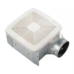
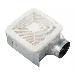
MODEL QTX110HFLT
QTX SERIES HEATER / FAN /
FLUORESCENT LIGHT / NIGHT LIGHT
READ AND SAVE THESE INSTRUCTIONS
IMPORTANT INSTRUCTIONS
READ ALL INSTRUCTIONS BEFORE INSTALLING OR
USING THIS HEATER.
To reduce the risk of fire, electric shock, or injury to persons, observe the fol-
lowing:
1. Use this unit only in the manner intended by the manufacturer. If you have
questions, contact the manufacturer at the address or telephone number
listed in the warranty.
2. Before servicing or cleaning unit, switch power off at service panel and lock
the service disconnecting means to prevent power from being switched on
accidentally. When the service disconnecting means cannot be locked,
securely fasten a prominent warning device, such as a tag, to the service
panel.
3. Installation work and electrical wiring must be done by a qualified person(s)
in accordance with all applicable codes and standards, including fire-rated
construction codes and standards.
4. When cutting or drilling into wall or ceiling, do not damage electrical wiring
and other hidden utilities.
5. This heater is hot when in use. To avoid burns, do not let bare skin touch
hot surfaces. Keep combustible materials, such as furniture, pillows, bed-
ding, papers, clothes, etc. and curtains at least 3 feet (0.9 m) from the front
of the heater.
6. Extreme caution is necessary when any heater is used by or near children
or invalids and whenever the heater is left operating and unattended.
7. Do not operate any heater after it malfunctions. Disconnect power at ser-
vice panel and have heater inspected by a reputable electrician before
reusing.
8. Do not use outdoors.
9. To disconnect heater, turn controls to off, and turn off power to heater cir-
cuit at main disconnect panel (or operate internal disconnect switch, if
provided).
10. Do not insert or allow foreign objects to enter any ventilation or exhaust
opening, as this may cause an electric shock or fire, or damage the heater.
11. To prevent a possible fire, do not block air intakes or exhaust in any man-
ner.
12. A heater has hot and arcing or sparking parts inside. Do not use it in areas
where gasoline, paint, or flammable vapors or liquids are used or stored.
13. Use this heater only as described in this manual. Any other use not recom-
mended by the manufacturer may cause fire, electric shock, or injury to
persons.
14. This product must be grounded.
15. Do not install heater in a tub or shower enclosure.
16. This product is designed for installation in ceilings up to a 12/12 pitch. Duct
connector must point up. DO NOT MOUNT THIS PRODUCT IN A WALL.
17. Install heater in ceiling only - at least 6 inches from any wall.
18. Do not connect heater to dimmer switch or speed control.
19. Provide a separate 20 AMP circuit. Use 12 GA. power cable of type which
meets code. Use supply wiring rated for at least 90
O
C.
20. For greatest efficiency, install heater so heat is directed toward tub or shower
area. Avoid directing toward walls or windows.
SAVE THESE INSTRUCTIONS
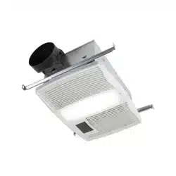
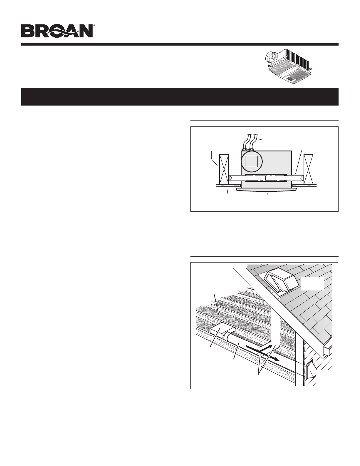
TYPICAL INSTALLATION
HOUSING
CEILING
JOIST, TRUSS,
OR I-JOISTS
MOUNTING
CHANNELS
GRILLE
CEILING
MATERIAL
POWER
CABLES
Housing mounted directly to joists, trusses, or I-joists.
Up to 24-inches on-center.
PLANNING
The unit will operate most quietly and efficiently when located
where the shortest possible duct run and minimum number of
elbows will be needed.
Use a roof cap or wall cap that has a built-in damper to reduce
backdrafts.
Plan to supply the unit with proper line voltage and appropriate
power cable.
ROOF
CAP
*
6-IN. ROUND
ELBOW(S)
*
6-IN.
ROUND
DUCT
*
WALL
CAP
*
*
Purchase
separately
INSULATION
(Can be placed
around and over
fan housing.)
FAN
HOUSING
Page 2
MODEL QTX110HFLT
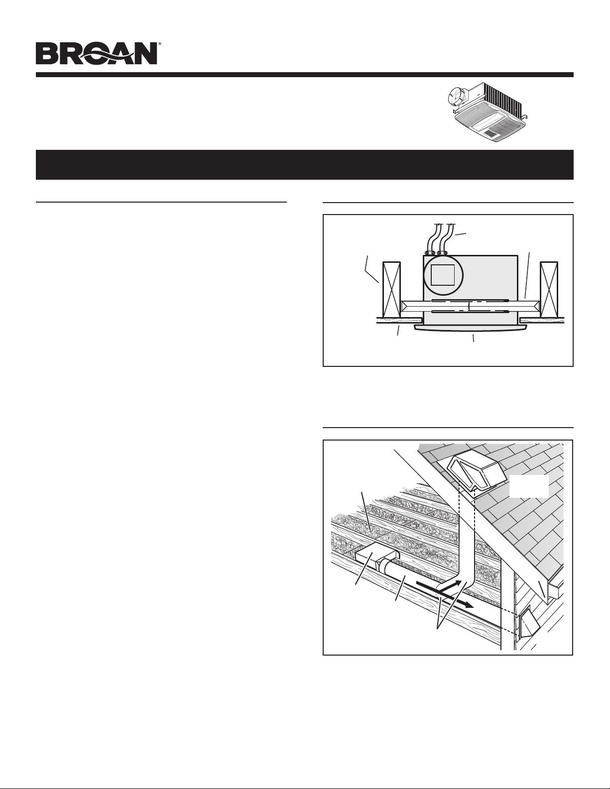
2. Mount hous-
ing.
Secure hous-
ing to ceiling
structure with (4)
mounting screws.
Make sure bottom
of housing will be
flush with finished
ceiling material.
1. Insert
mounting
brackets.
Slide the (4)
mounting brack-
ets into the chan-
nels on each end
of the housing.
3. Attach
damper
/ duct
connector
to housing.
Snap damper /
duct connector
onto housing.
Make sure con-
nector is flush
with top of hous-
ing and damper
flap falls closed.
4. Install
6-inch
round duct-
work.
Connect 6-inch
round ductwork
to damper / duct
connector. Run
ductwork to a
roof cap or wall
cap. Tape all
ductwork con-
nections to make them secure and air tight.
INSTALLATION
WARNING: To reduce the risk of fire, do not store or use
gasoline or other flammable vapors and liquids in the vicinity
of the heater.
CAUTION: High temperature, risk of fire, keep electrical cords,
drapery, furnishings, and other combustibles at least 3 feet
(0.9 m) from the front of the heater and away from the side
and rear.
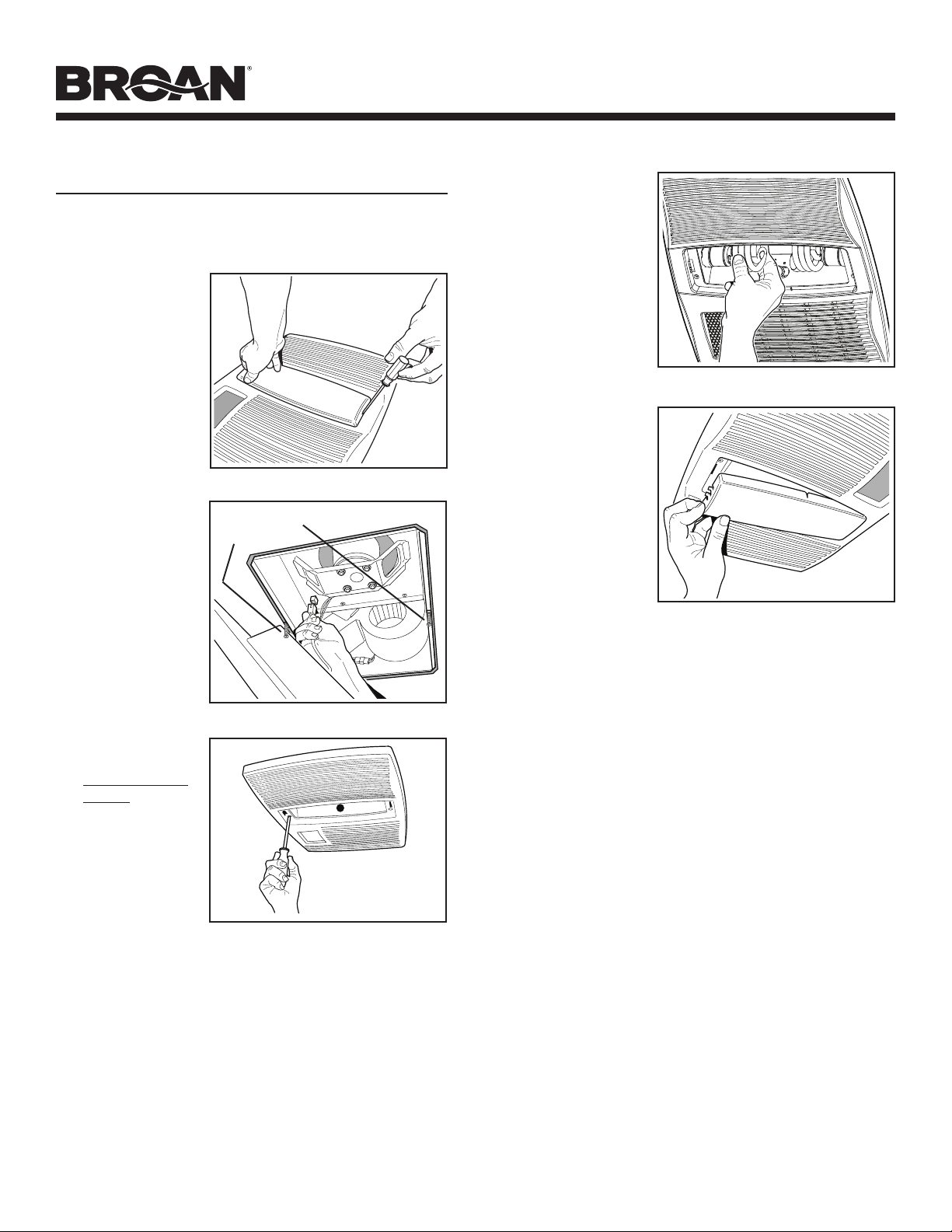
5. Connect electrical wiring.
Run 120 VAC house wiring to installation location. Use
proper UL approved connectors to secure house wiring to
wiring plate. Connect wires as shown in wiring diagram(s).
CONNECT WIRING
GREEN
WHITE
to
WHITE
HEAT (2-position rocker)
LIGHT (red)
NIGHT LIGHT (blue)
(3-position rocker)
4-FUNCTION CONTROL
GROUND
120 VAC LINE IN
BLACK to BLUE
BLACK to RED
BLACK to BLACKS
FAN (2-position rocker)
RED
WIRING PLATE
FROM VENTILATOR
VENTILATOR
HOUSING
LIGHT
&
FAN
HEAT
&
NIGHT LIGHT
BLACK to BLUE
(Light)
WHITE to WHITE with red stripe
RED to RED
(Fan)
RED to BLACK
(Heat)
BLACK to YELLOW
(Night Light)
WHITE to WHITE
RED
CAUTION
RATING SPECIFICATIONS
The three-position
rocker switch is rated
5 A @ 125VAC. Use this
switch for Lights ONLY.
Each two-position rocker
switch is rated 15 A @ 120VAC. Use these switches for Heat and Vent.
The total load on this control must not exceed 20 A @ 120VAC.
Broan 4-Function
Control shown
(purchase separately)
Installation work and electrical wiring must be done by a quali-
fied person(s) in accordance with all applicable codes and stan-
dards, including fire-rated construction codes and standards.
Page 3
MODEL QTX110HFLT
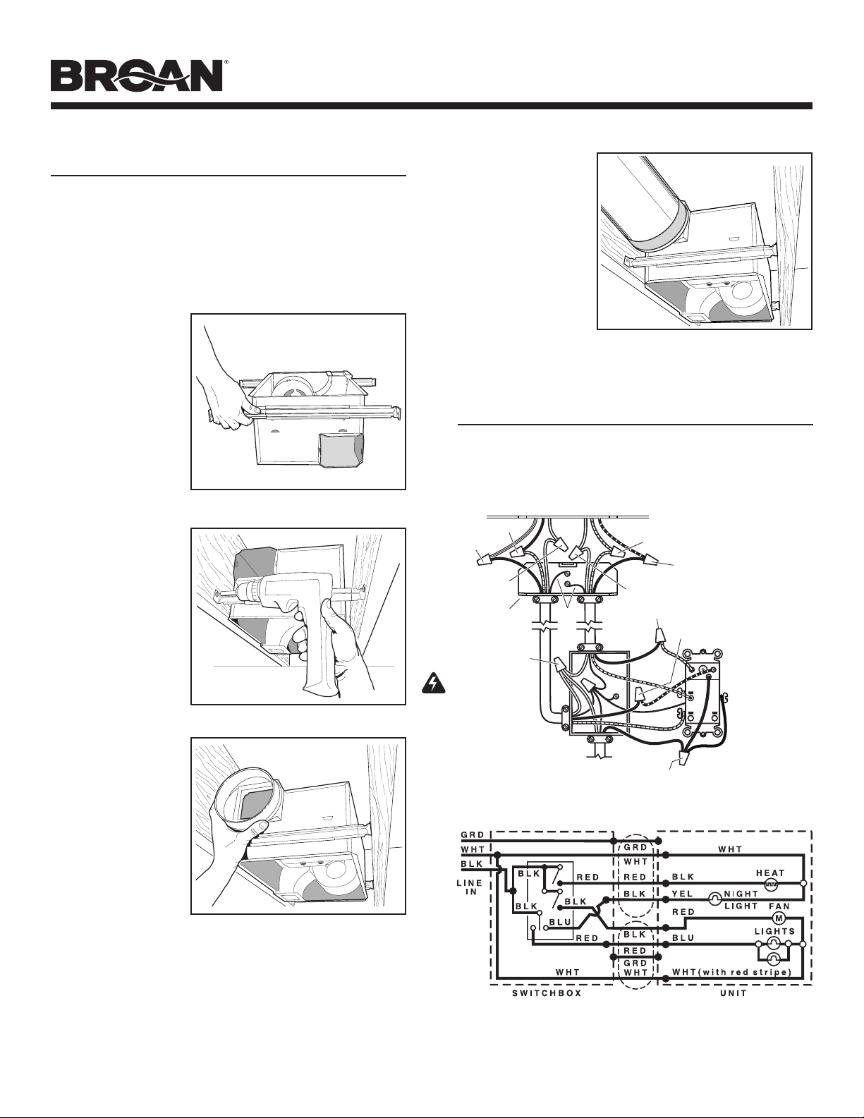
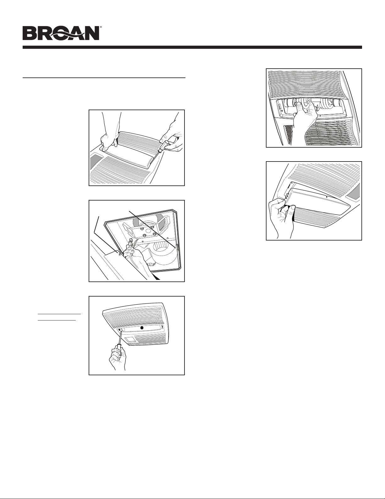
8. Plug-in
light.
Hold grille as-
sembly up near
housing. Connect
light plug from
grille assembly to
receptacle inside
of housing.
9. Attach grille.
Remove the (2)
grille mounting
screws from the
sides of the hous-
ing. (See Step 8
illustration.) Use
these screws to
attach the grille
to the housing as
shown.
To avoid damage
to the grille: DO NOT OVERTIGHTEN SCREWS. Tighten
screws only until grille is snug against ceiling material.
10. Install
bulbs.
The unit
accepts (2)
18-Watt 3500K
(maximum),
GU24 based
fluorescent
bulbs and (1)
7-Watt night
light bulb.
GRILLE MOUNTING
SCREWS
INSTALL GRILLE & BULBS
7. Remove
light lens
from grille.
Insert a small
flat-bladed screw-
driver into the slot
at one end of the
light lens. Care-
fully pry the lens
out.
6. Finish ceiling.
Install ceiling material. Cut out ceiling material closely
around housing.
11. Attach
light lens.
Hook the tabs
on one end of
the lens into the
slot in the grille.
Lift other end
of lens up and
snap into place.
Page 4
MODEL QTX110HFLT
OPERATION
Before using heater, make sure heater has been properly installed
according to installation steps beginning with the "TYPICAL IN-
STALLATION" section on page 1.
Use a 4-Function Control to operate the heater, fan, light, and
night light separately. See “Connect Wiring” for details.

Page 5
MODEL QTX110HFLT
MAINTENANCE
The following maintenance and cleaning tasks can be performed
by the user. All other servicing must be performed by an autho-
rized technician If you have any questions, please consult with
our customer service department at: 800-558-1711.
TO REPLACE BULB
Replace light bulbs with (2) 18-Watt 3500K (maximum), GU24
based fluorescent lamps and (1) 7-Watt night light bulb.
LUBRICATION
The heater is permanently lubricated and never needs oiling or
disassembly.
CLEANING
Clean heater once a month as follows:
1. Turn off power at service panel.
2. Make sure heating element is cool.
3. Use a soft brush attachment to gently vacuum grille openings
or wipe grille clean with a soft cloth.
4. Restore power.
CAUTION: METAL AND ELECTRICAL PARTS SHOULD NEVER
BE IMMERSED IN WATER.
BROAN-NUTONE THREE YEAR LIMITED WARRANTY
Broan-NuTone warrants to the original consumer purchaser of its products that such products will be
free from defects in materials or workmanship for a period of three years from the date of original pur-
chase. THERE ARE NO OTHER WARRANTIES, EXPRESS OR IMPLIED, INCLUDING, BUT NOT LIMITED
TO, IMPLIED WARRANTIES OF MERCHANTABILITY OR FITNESS FOR A PARTICULAR PURPOSE.
During this three-year period, Broan-NuTone will, at its option, repair or replace, without charge, any
product or part which is found to be defective under normal use and service.
THIS WARRANTY DOES NOT EXTEND TO FLUORESCENT LAMP STARTERS AND TUBES. This
warranty does not cover (a) normal maintenance and service or (b) any products or parts which
have been subject to misuse, negligence, accident, improper maintenance or repair (other than by
Broan-NuTone), faulty installation or installation contrary to recommended installation instructions.
The duration of an implied warranty is limited to the three-year period as specified for the express
warranty. Some states do not allow limitation on how long an implied warranty lasts, so the above
limitation may not apply to you.
BROAN-NUTONE’S OBLIGATION TO REPAIR OR REPLACE, AT BROAN-NUTONE’S OPTION, SHALL
BE THE PURCHASER’S SOLE AND EXCLUSIVE REMEDY UNDER THIS WARRANTY. BROAN-NUTONE
SHALL NOT BE LIABLE FOR INCIDENTAL, CONSEQUENTIAL OR SPECIAL DAMAGES ARISING OUT OF
OR IN CONNECTION WITH PRODUCT USE OR PERFORMANCE. Some states do not allow the exclusion
or limitation of incidental or consequential damages, so the above limitation may not apply to you.
This warranty gives you specific legal rights, and you may also have other rights, which vary from
state to state. This warranty supersedes all prior warranties.
To qualify for warranty service, you must (a) notify Broan-NuTone at the address or telephone number
stated below, (b) give the model number and part identification and (c) describe the nature of any
defect in the product or part. At the time of requesting warranty service, you must present evidence
of the original purchase date.
Broan-NuTone LLC Hartford, Wisconsin www.broan.com 800-558-1711
WARRANTY
Page 6
MODEL QTX110HFLT
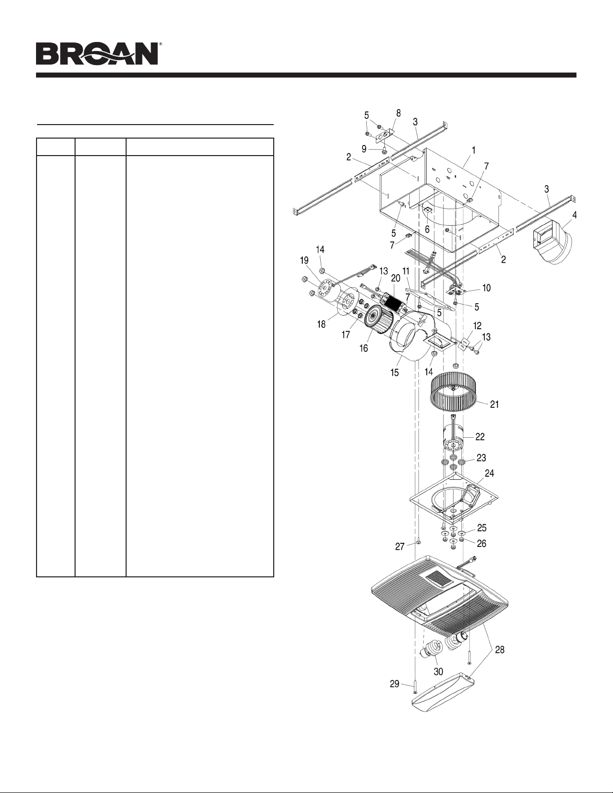
SERVICE PARTS
Key No. Part No. Description
1 97016470 Housing
2 98007763 Slide Channel (2 req.)
3 98003036 Support Angle (4 req.)
4 97016450 Duct Connector
5 99170245 Screw #8-18 X .375 (8 req.)
6 93260454 Nut, Sheet Metal #8-18 (Partition)
(2 req.)
7 99260512 Nut, Sheet Metal #8-18 (Grille)
(3 req.)
8 98010091 Cover/KO Panel
9 99150471 Screw, Ground (2 req.)
10 97018049 Wire Panel/Harness Assembly
11 98010090 Wire Compartment
12 98010089 Mounting Bracket-Heater
13 99150415 Screw #8-18 X .250 (4 req.)
14 99260488 Nut, Hex #10-24 (5 req.)
15 97016564 Heater Scroll
16 99020283 Wheel-Heater
17 99260423 Nut, Hex #8-32 (4 req.)
18 98010088 Motor Mount
19 99080558 Motor-Heater
20 97020888 Heating Element
(includes Key No. 7)
97020889 Heater Scroll Assembly
(includes Key Nos. 12 thru 20)
21 99020284 Wheel-Fan
22 99080556 Motor-Fan
23 99100491 Isolator (4 req.)
24 97016471 Partition
25 99250959 Washer (4 req.)
26 99260558 Nut, Hex Lock #8-32 (4 req.)
97016567 Blower Assembly
(includes Key Nos. 21 thru 26)
27 93150459 Screw #8-18 X .500 (2 req.)
28 97018035 Grille Assembly
29 99150622
Screw, Grille #8-18 X 2.000 (2 req.)
30 99271381 Lamp, Fluorescent
18 W, 3500K, GU24 (2 req.)
99045042C
Página 7
MODELO QTX110HFLT
SERIE QTX CALEFACTOR / VENTILADOR /
LUZ FLUORESCENTE / LUZ DE NOCHE
LEA Y CONSERVE ESTAS INSTRUCCIONES
INSTRUCCIONES IMPORTANTES
LEA TODAS LAS INSTRUCCIONES ANTES DE INSTALAR
O USAR ESTE CALENTADOR.
Para reducir el riesgo de incendios, descargas eléctricas o lesiones personales, observe
las siguientes precauciones:
1. Use la unidad solo de la manera indicada por el fabricante. Si tiene preguntas,
comuníquese con el fabricante a la dirección o al número telefónico que se incluye
en la garantía.
2. Antes de dar servicio a la unidad o de limpiarla, interrumpa el suministro eléctrico
en el panel de servicio y bloquee los medios de desconexión del servicio para evitar
que la electricidad se reanude accidentalmente. Cuando no sea posible bloquear
los medios de desconexión del servicio, fije firmemente una señal de advertencia
(como una etiqueta) en un lugar visible del panel de servicio.
3. El trabajo de instalación y el cableado eléctrico deben estar a cargo de personal
capacitado, de acuerdo con todos los códigos y normas correspondientes,
incluidos los códigos y normas de construcción específicos sobre protección contra
incendios.
4. Al cortar o perforar a través de la pared o del cielo raso, tenga cuidado de no dañar
el cableado eléctrico ni otros servicios ocultos.
5. Este calentador se calienta cuando se usa. Para evitar quemaduras, no deje que
la piel desnuda toque las superficies calientes. Mantenga materiales combustibles
como muebles, almohadas, ropa de cama, papeles, ropa, etc., así como las
cortinas, por lo menos a 3 pies (0.9 m) de la parte delantera del calentador.
6. Es necesario tener extremo cuidado cuando se use un calentador cerca de niños o
personas inválidas, y siempre que el calentador se deje funcionando y sin atención.
7. No haga funcionar ningún calentador después de que presente una falla.
Desconecte la energía eléctrica en el panel de servicio y pida que un electricista
acreditado inspeccione el calentador antes de volverlo a usar.
8. No lo use en exteriores.
9. Para desconectar el calentador, mueva los controles a la posición de apagado y
desconecte la energía eléctrica al circuito del calentador en el panel de desconexión
principal (o active el interruptor de desconexión interna, si existe).
10. No inserte ni permita que objetos extraños entren en la abertura de ventilación
o de escape, pues esto puede ocasionar una descarga eléctrica, un incendio o
daños al calentador.
11. Para prevenir un posible incendio, no bloquee la entrada o salida del aire de ninguna
manera.
12. El calentador tiene piezas calientes y que pueden generar arcos eléctricos o
chispas en el interior. No lo use en áreas donde se use o almacene gasolina,
pintura o vapores o líquidos flamables.
13. Use este calentador solamente como se describe en este manual. Cualquier otro
uso no recomendado por el fabricante puede ocasionar un incendio, una descarga
eléctrica o lesiones a personas.
14. Este producto debe ser conectado a tierra.
15. No instale esta unidad sobre una bañera o ducha.
16. Este producto se diseña para la instalación en techos hasta una echada de 12/12.
Conector de conductor debe señalar hacia arriba. NO MONTE ESTE PRODUCTO
EN UNA TECHO.
17. Instálelo únicamente en techos, a distancias mínimas de 6 pulg. (15 cm) de
cualquier pared.
18. No conecte el calentador a un variador de luz o control de velocidad.
19. Proporcione un circuito por separado de 20 A. Utilice un cable eléctrico calibre
12 de un tipo conforme al código. Utilice un cable eléctrico clasificado para por lo
menos 90
O
C.
20. Para asegurar una mayor eficiencia, instale el calentador de manera que el calor
esté dirigido hacia el área de la bañera o ducha. Evite dirigir el calor hacia paredes
o ventanas.
GUARDE ESTAS INSTRUCCIONES
INSTALACIÓN TÍPICA
CUBIERTA
RANURAS
DE MONTAJE
REJILLA
VIGA DE TECHO,
TIRANTE O
VIGA EN I
MATERIAL DEL
CIELO RASO
CABLES DE
ELECTRICIDAD
La cubierta se monta directamente sobre las
vigas, tirantes o vigas en I.
Hasta 24 pulgadas en centro.
PLANIFICACIÓN
El ventilador funcionará con más eficiencia y menos ruido si se
ubica en un sitio donde requiera el tramo de conducto más corto
posible y un mínimo número de codos.
Instale una tapa de techo o de pared que tenga un regulador de
tiro incorporado a fin de reducir los contratiros.
Alimente la unidad con el voltaje de línea y el cable eléctrico
apropiados.
CODO REDONDO
DE 6 PULG.
*
CUBIERTA DE
VENTILADOR
CONDUCTO
REDONDO DE
6 PULG.
*
* Se compran
por separado
TAPA
DE
PARED *
TAPA DE
TECHO *
AISLAMIENTO
(Puede ser colo-
cado alrededor y
sobre de la cubierta
del ventilador.)
Página 8
MODELO QTX110HFLT
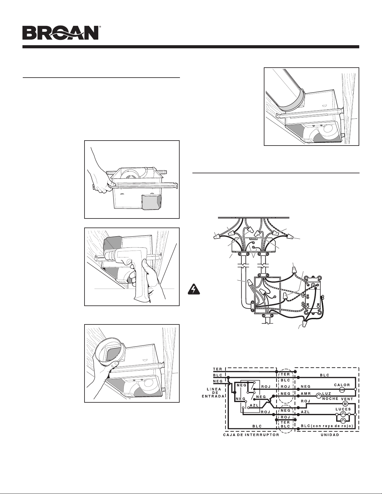
INSTALACIÓN
2. Monte la
cubierta.
Fije la cubierta a la
estructura del cielo
raso con cuatro (4)
tornillos de mon-
taje. Asegúrese de
que la parte infe-
rior de la cubierta
esté a nivel con el
material terminado
del cielo raso.
1. Inserte los
soportes de
montaje.
Deslice los (4) so-
portes de montaje
en las ranuras en
cada extremo de la
cubierta.
3. Acople el
conector del
regulador
de tiro/con-
ducto a la
cubierta.
Conecte a presión
el conector del
regulador de tiro/
conducto en la cu-
bierta. Asegúrese
de que el conector esté al ras con la parte superior de la
cubierta y que la aleta del regulador caiga cerrada.
4. Instale el conducto
redondo de 6 pulg.
Conecte el conducto
redondo de 6 pulg. al
conector del regulador
/ conducto. Extienda
el conducto hacia una
tapa de techo o tapa
de pared. Encinte
todas las conexiones
de los conductos para
fijarlas y hacerlas
herméticas al aire.
ADVERTENCIA: Para reducir el riesgo de incendio, no almacene
ni use gasolina u otros vapores y líquidos flamables en las
cercanías del calentador.
PRECAUCIÓN: Temperatura alta, el riesgo de incendio, mantenga
los cables eléctricos, cortinas, muebles y otros materiales
combustibles por lo menos 3 pies (0,9 m) del frente del calentador
y lejos de la cara y la parte trasera.
5. Conecte los cables eléctricos.
Extienda el cableado de la casa de 120 VCA al lugar de la in-
stalación. Utilice conexiones aprobadas por UL para asegurar el
cableado de la casa a la placa de cableado. Conecte los cables tal
como se ilustra en los diagramas de cableado.
CONEXIÓN ELÉCTRICA
BLANCO
a
BLANCO
CALENTADOR
(interruptor 2-posición)
LUZ (rojo)
LUZ DE NOCHE (azul)
(3-position rocker)
CONTROL DE
4 FUNCIONNES
TIERRA
LINEA DE ENTRADA
120 VCA
NEGRO a AZUL
NEGRO a ROJO
NEGRO a NEGROS
VENTILADOR
(interruptor 2-posición)
ROJO
ROJO
PLACA DE CABLE
DE VENTILADOR
CAJA DEL VENTILADOR
LUZ
Y
VENTILADOR
CALENTADOR
Y
LUZ DE NOCHE
NEGRO a AZUL
(Luz)
ROJO a ROJO
(Ventilador)
ROJO a NEGRO
(Calentador)
NEGRO a AMARILLO
(Luz de noche)
BLANCO a BLANCO
BLANCO a BLANCO con raya de rojo
CUIDADO
ESPECIFICACIONES
DEL GRADO
El interruptor de eje
de balancín de tres
posiciones es clasificado
5 A @ 125VCA. Utilice
este interruptor para las luces SOLAMENTE.
El interruptor de eje de balancín de dos posiciones es clasificado 15
A @ 120VCA. Utilice estos interruptores para el calor y el ventilador.
La carga total en este control no debe excederse 20 A @ 120VCA.
Broan control para
4-funciones ilustrado
(comprar separado)
El trabajo de instalación y el cableado eléctrico deben estar a cargo
de personal capacitado, de acuerdo con todos los códigos y normas
correspondientes, incluidos los códigos y normas de construcción
especícos sobre protección contra incendios.
Página 9
MODELO QTX110HFLT
8. Conecte el
foco.
Sostenga el
conjunto de la
rejilla cerca de la
cubierta. Conecte
el foco del con-
junto de la rejilla al
receptáculo dentro
de la cubierta.
9. Fije la rejilla.
Quite los dos (2)
tornillos de mon-
taje de la rejilla
de los lados de
la cubierta. (Vea
la ilustración de
paso 8.) Utilice
estos tornillos
para fijar la rejilla
a la cubierta, tal
como se muestra.
Para evitar daños
en la rejilla: NO APRIETE DE MÁS LOS TORNILLOS. Apriete
los tornillos hasta que la rejilla esté firmemente ceñida contra
el material del cielo raso.
10. Instale los
focos.
La unidad acepta
dos (2) focos
fluorescentes de
18 watts 3500K
(máximo), base
de GU24 y un
(1) foco de luz
nocturna de
7 watts.
TORNILLOS DE MONTAJE DE
LA REJILLA
INSTALE LA REJILLA Y LOS FOCOS
7. Quite la lente
del foco de la
rejilla.
Inserte un pequeño
destornillador
plano en la rejilla
en un extremo de
la lente del foco.
Haga palanca con
cuidado para retirar
la lente.
6. Termine el cielo raso.
Instale el material del cielo raso. Recorte el material del cielo
raso de cerca alrededor de la cubierta.
11. Fije la lente
de la luz.
Enganche las
lengüetas por
un extremo de
la lente en la
ranura de la rejilla.
Levante el otro
extremo de la
lente y fíjela en su
lugar.

Page 10
MODEL QTX110HFLT
OPERACIÓN
Antes de usar el calentador, asegúrese de que esté instalado adecuada-
mente, de acuerdo con los pasos de instalación indicados en “INSTA-
LACIÓN TYPICA” en la página 7.
Utilice un control de 4 funciones para operar el calefactor, el ventilador,
la luz y la luz nocturna por separado (vea los detalles en la sección
“Conexión eléctrica”).
Page 11
MODEL QTX110HFLT
GARANTIA
GARANTIA BROAN-NUTONE LIMITADA POR TRES AÑOS
Broan-NuTone garantiza al consumidor comprador original de sus productos que dichos productos
carecerán de defectos en materiales o en mano de obra por un período de tres años a partir de la
fecha original de compra. NO EXISTEN OTRAS GARANTIAS, EXPLICITAS O IMPLICITAS, INCLUY-
ENDO, PERO NO LIMITADAS A, GARANTIAS IMPLICITAS DE COMERCIALIZACION O APTITUD
PARA UN PROPOSITO PARTICULAR.
Durante el período de tres años, y a su propio criterio, Broan-NuTone reparará o reemplazará, sin
costo alguno cualquier producto o pieza que se encuentre defectuosa bajo condiciones normales
de servicio y uso.
ESTA GARANTIA NO SE APLICA A TUBOS Y ARRANCADORES DE LAMPARAS FLUORESCENTES.
Esta garantía no cubre (a) mantenimiento y servicio normales o (b) cualquier producto o piezas que
hayan sido utilizadas de forma errónea, negligente, que hayan causado un accidente, o que hayan
sido reparadas o mantenidas inapropiadamente (por otras compañías que no sean Broan-NuTone),
instalación defectuosa, o instalación contraria a las instrucciones de instalación recomendadas.
La duración de cualquier garantía implícita se limita a un período de tres años como se especifica
en la garantía expresa. Algunos estados no permiten limitaciones en cuanto al tiempo de expiración
de una garantía implícita, por lo que la limitación antes mencionada puede no aplicarse a usted.
LA OBLIGACION DE BROAN-NUTONE DE REPARAR O REEMPLAZAR, SIGUIENDO EL CRITERIO
DE BROAN-NUTONE, DEBERA SER EL UNICO Y EXCLUSIVO RECURSO LEGAL DEL COMPRADOR
BAJO ESTA GARANTIA. BROAN-NUTONE NO SERA RESPONSABLE POR DAÑOS INCIDENTALES,
CONSIGUIENTES, O POR DAÑOS ESPECIALES QUE SURJAN A RAIZ DEL USO O DESEMPEÑO
DEL PRODUCTO. Algunos estados no permiten la exclusión o limitación de daños incidentales o
consiguientes, por lo que la limitación antes mencionada puede no aplicarse a usted.
Esta garantía le proporciona derechos legales específicos, y usted puede también tener otros
derechos, los cuales varían de estado a estado. Esta garantía reemplaza todas las garantías anteriores.
Para calificar en la garantía de servicio, usted debe (a) notificar a Broan-NuTone al domicilio o al
número de teléfono abajo, (b) dar el número del modelo y la identificación de la pieza, y (c) describir
la naturaleza de cualquier defecto en el producto o pieza. En el momento de solicitar servicio cubierto
por la garantía, usted debe de presentar evidencia de la fecha original de compra.
Broan-NuTone LLC Hartford, Wisconsin www.broan.com 800-558-1711
MANTENIMIENTO
El usuario puede realizar las siguientes tareas de mantenimiento
y limpieza. Todos los demás servicios los debe realizar un técnico
autorizado. Si tiene preguntas, consulte a nuestro departamento
de servicio al cliente llamando al: 800-558- 1711.
PARA REEMPLAZAR LA LAMPARA
Reemplace las lámparas con dos (2) lámparas fluorescentes de
18 watts 3500K (máximo), base de GU24 y un (1) foco de luz
nocturna de 7 watts.
LUBRICACIÓN
El calentador está permanentemente lubricado y nunca necesi-
tará ponerle aceite ni desarmarlo.
LIMPIEZA
Limpie el calentador una vez al mes tal como sigue:
1. Apague la energía eléctrica en el panel de servicio.
2. Asegúrese de que el elemento de calefacción esté frío.
3. Use un aditamento de cepillo suave para aspirar suavemente
aberturas de la rejilla o limpie la rejilla con un paño suave.
4. Restaure la energía eléctrica.
CUIDADO: LAS PIEZAS METALICAS Y ELECTRICAS NUNCA
SE DEBEN SUMERGIR EN AGUA.

Página 12
MODELO QTX110HFLT
PIEZAS DE REPUESTO
Clave No.
Pieza No. Descripción
1 97016470 Cubierta
2 98007763 Ranura de deslizamiento
(se req. 2)
3 98003036 Ángulo de soporte (se req. 4)
4 97016450 Conector del conducto
5 99170245 Tornillo, #8-18 x 0.375 (se req. 8)
6 93260454 Tuerca de chapa #8-18 (División)
(se req. 2)
7 99260512 Tuerca de chapa #8-18 (Rejilla)
(se req. 3)
8 98010091 Cubierta/ Panel KO
9 99150471 Tornillo de conexión a tierra
(se req. 2)
10 97018049 Conjunto del panel de
cableado/arnés
11 98010090 Compartimiento de cables
12 98010089 Soporte de montaje-Calefactor
13 99150415 Tornillo, #8-18 x 0.250 (se req. 4)
14 99260488 Tuerca hexagonal #10-24
(se req. 5)
15 97016564 Desplazador del calefactor
16 99020283 Disco-Calefactor
17 99260423 Tuerca hexagonal #8-32
(se req. 4)
18 98010088 Montaje del motor
19 99080558 Motor-Calefactor
20 97020888 Elemento de calefacción
(incluye clave no. 7)
97020889 Conjunto del desplazador del
calefactor (incluye clave nos.
12 á 20)
21 99020284 Disco-Ventilador
22 99080556 Motor-Ventilador
23 99100491 Aislante (se req. 4)
24 97016471 División
25 99250959 Arandela (se req. 4)
26 99260558 Tuerca hexagonal de
seguridad #8-32 (se req. 4)
97016567 Conjunto del ventilador
(incluye clave nos. 21 á 26)
27 93150459 Tornillo, #8-18 x 0.500 (se req. 2)
28 97018035 Conjunto de la rejilla
29 99150622
Tornillo de la rejilla, #8-18 x
2.000
(se req. 2)
30 99271381
Lámpara, fluorescente, 18 W,
3500K, base de GU24 (se req. 2)
99045042C