Loading ...
Loading ...
Loading ...
PRODUCTDAMAGEHAZARD
Failuretofollowthiscautionmayresultin productor
propertydamage.
AbrazingshieldMUSTbeusedwhentubingsetsarebeing
brazedtotheunitconnectionstopreventdamagetotheunit
surfaceandcondensatepanfittingcaps.
Unitshavesweatsuctionandliquidtubeconnections.Make
suctiontubeconnectionfirst.
1.Cuttubingtocorrectlength.
2.Inserttubeintosweatconnectiononunituntilitbottoms.
3.Brazeconnectionusingsilverbearingornon-silverbearing
brazingmaterials.Donotusesolder(materialswhichmelt
below800°F/ 427°C). Consult local code requirements.
4. Evacuate coil and tubing system to 500 microns using deep
vacuum method.
PRODUCT DAMAGE HAZARD
Failure to follow this caution may result in product or
property damage.
Wrap a wet cloth around rear of fitting to prevent damage to
TXV and factory-made joints.
Step 6 -- Refrigerant Flow-Control Device
Tire FX4C and FY4A are equipped with PuronCR) refrigerant TXV.
Use outdoor units designed for Purnn(A) refrigerant only.
PRODU('T OPERATION HAZARD
Failure to follow this caution may result in improper product
operation.
If using a TXV in conjunction with a single-phase
reciprocating compressor, a compressor start capacitor and
relay are required. Consult outdoor unit pre-sale literature for
start assist kit part number.
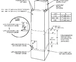
Step 7 -- Condensate Drains
To connect drains, the cap openings must be removed. Use a knife
to start the opening near the tab and using pliers, pull the tab to
remove the disk. Clean the edge of the opening if necessary and
install the condensate line. Finally caulk around the lines where
they exit the fitting to retain the low leak rating of the unit.
UNIT OR PROPERTY DAMAGE HAZARD
Failure to fnllow this caution may result in product or
property damage.
The conversion of the fan coil to downflow requires special
procedures for the condensate drains on both A-coil and
slope units. The vertical drains have an overflow hole
between the primary and secondary drain holes. This hole is
plugged for all applications except downflow, but must be
used for downflow. During the conversion process, remove
the plastic cap covering the vertical drains only and discard.
Remove the plug from the overflow hole and discard. At
completion of the downflow installation, caulk around the
vertical pan fitting to door joint to retain the low air leak
performance of the unit.
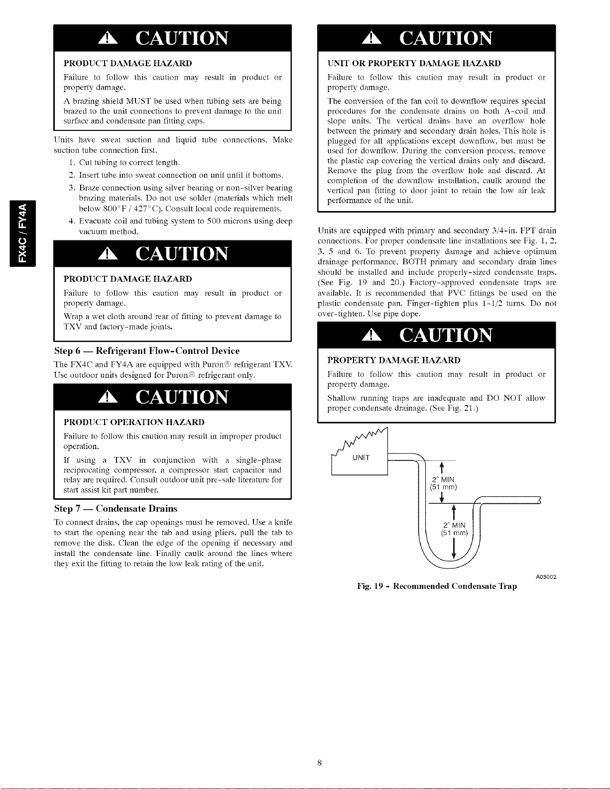
Units are equipped with primary and secondary 3/4-in. FPT drain
connections. For proper condensate line installations see Fig. 1, 2.
3, 5 and 6. To prevent property damage and achieve optimum
drainage performance. BOTH primary and secondary drain lines
should be installed and include properly-sized condensate traps.
(See Fig. 19 and 20.) Factory-approved condensate traps are
available. It is recommended that PVC fittings be used on the
plastic condensate pan. Finger-tighten plus 1-1/2 turns. Do not
over-tighten. Use pipe dope.
PROPERTY DAMAGE HAZARD
Failure to follow this caution may result in product or
property damage.
Shallow running traps are inadequate and DO NOT allow
proper condensate drainage. (See Fig. 21.)
UNIT
f
2" MIN
(51 mm)
Fig. 19 - Recommended Condensate Trap
A03002
Loading ...
Loading ...
Loading ...