Loading ...
Loading ...
Loading ...
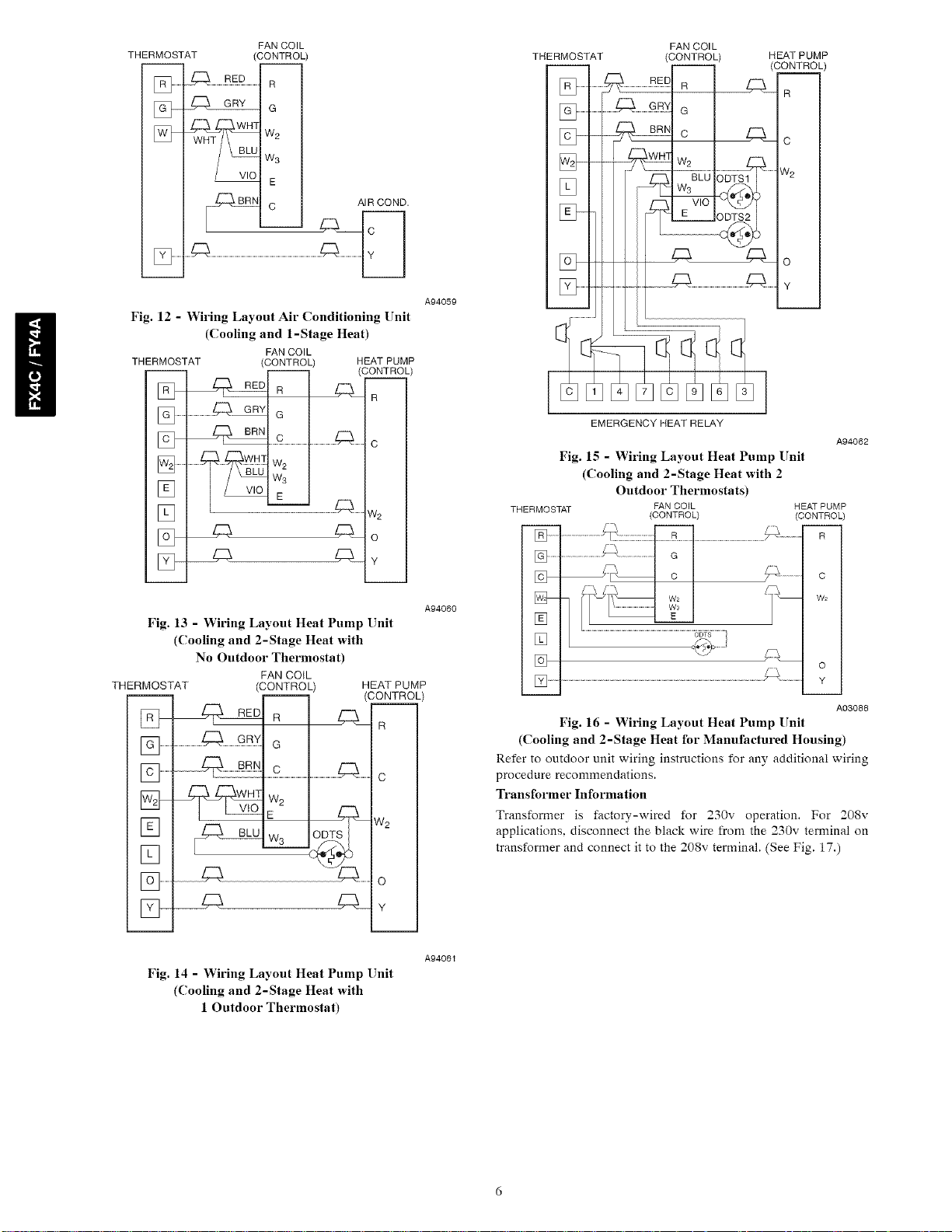
THERMOSTAT
] .............
] ............
FAN COIL
(CONTROL)
...............R
WriT WH3 W2
BLU W3
C AIR COND.
Fig. 12 - Wiring Layout Air Conditioning Unit
(Cooling and 1-Stage Heat)
FAN COIL
THERMOSTAT (CONTROL) HEAT PUMP
] .........
] .........
[]
[]
_R
.........................Z_, GRY G
...........w:
_77x
5:5 z_
CONTRL)
R
C
W2
O
Y
A94059
A94060
Fig, 13 - Wiring Layout Heat Pump Unit
(Cooling and 2-Stage Heat with
No Outdoor Thermostat)
FAN COiL
THERMOSTAT (CONTROL) HEAT PUMP
-- -- (CONTROL)
R
[] ..........................................G
[] ............. ........................................................c
_- _-,WHT W
] ..........
] ............. O
[Z]__ Z:a_y
Fig. 14 - Wiring Layout Heat Pump Unit
(Cooling and 2-Stage Heat with
1 Outdoor Thermostat)
A94061
[]
FAN COl L
(CONTROL)
R
G
_-Nc L:_
H_ W2
BL--UoSTS 1_ .........
E VlO
HEAT PUMP
(CONTROL)
C:5_ R
c
_v2
o
Y
EMERGENCY HEAT RELAY
A94062
Fig. 16 - Wiring Layout Heat Pump Unit
(Cooling and 2-Stage Heat for Manufactured Housing)
Refer to outdoor unit wiring instructions for any additional wiring
procedure recommendations.
Transformer Information
Transformer is factory-wired for 230v operation. For 208v
applications, disconnect the black wire from the 230v terminal on
transformer and connect it to the 208v terminal. (See Fig. 17.)
A03088
Fig. 15 - Wiring Layout Heat Pump Unit
(Cooling and 2-Stage Heat with 2
Outdoor Thermostats)
THERMOSTAT FAN COIL HEAT PUMP
(CONTROL) (CONTROL)
] ................................................... .............
] .........
[]
Loading ...
Loading ...
Loading ...