Loading ...
Loading ...
Loading ...
AIRFLOW PERFORMANCE TABLES
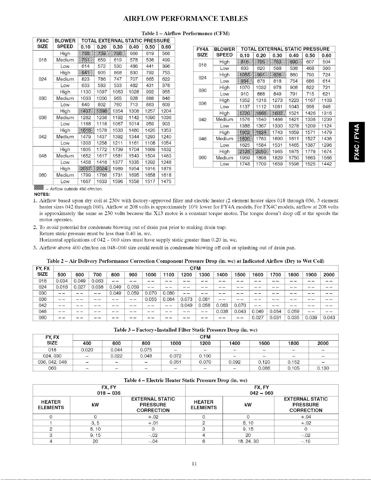
Table 1 - Airflow Performance (CFM)
FX4C BLOWER TOTAL EXTERNAL STATIC PRESSURE
SIZE SPEED 0.10 0.20 0.30 0.40 0.50 0.60
High 666 619 566
018 Medium } 578 538 499
Low 614 572 530 486 441 396
High } 905 868 630 792 753
024 Medium 823 786 747 707 665 622
Low 633 583 533 482 431 378
High 1130 1097 1063 1028 992 955
030 Medium 1033 1000 965 928 888 846
Low 840 802 760 713 663 609
High 2_3 1354 1308 1257 1204
036 Medium 1282 1238 1192 1142 1090 1036
Low 1168 1118 1067 1014 959 903
High 1578 1533 1480 1420 1353
042 Medium 1479 1437 1392 1344 1293 1240
Low 1303 1258 1211 1161 1108 1054
High 1805 1772 1739 1704 1669 1632
048 Medium 1652 1617 1581 1543 1504 1463
Low 1458 1418 1377 1335 1292 1248
High 202 1989 1954 1916 1878
060 Medium 1799 1766 1731 1695 1658 1618
Low 1667 1633 1596 1558 1517 1475
- Airflow outside 450 cfm/ton.
NOTES:
FY4A BLOWER TOTAL EXTERNAL STATIC PRESSURE
SIZE SPEED 0.10 0.20 0.30 0.40 0.50 0.60
018 High _ _ , _90::[: 607 504
Low 633 620 588 538 468 380
024 High 99'1 9_ 860 793 724
Low 878 616 754 666 614
030 High 1070 1032 978 908 822 721
Low 910 888 849 791 715 621
036 High 1352 1316 1273 1223 1167 1103
Low 1137 1112 1081 1043 998 946
High 72 1521 1426 1316
042 Medium 1576 1540 1488 1421 1338 1239
Low 1388 1367 1330 1278 1209 1124
High 1743 1659 1571 1479
048 Medium !88 i763 1690 1611 1527 1436
Low 1625 1584 1531 1465 1387 1296
High 1965 1875 1778 1674
060 Medium 1959 1898 1829 1750 1663 1566
Low 1748 1709 1659 1598 1525 1442
1. Airflow based upon dry coil at 230v with factory-approved filter and electric heater (2 element heater sizes 018 through 036, 3 element
heater sizes 042 through 060). Airflow at 208 volts is approximately 10% lower for FY4A models. For FX4C models, airflow at 208 volts
is approximately the same as 230 volts because the X13 motor is a constant torque motor. The torque doesn't drop off at the speeds the
motor operates.
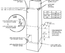
2. To avoid potential for condensate blowing out of drain pan prior to making drain trap:
Return static pressure must be less than 0.40 in. wc.
Horizontal applications of 042 - 060 sizes must have supply static greater than 0.20 in. wc.
3. Airflow above 400 cfm/ton on 048-060 size could result in condensate blowing off coil or splashing out of drain pan.
Table 2 - Air Delivery Performance Correction Component Pressm-e Drop (in. wc) at Indicated Airflow (Dry to Wet Coil)
FY, FX CFM
SIZE 500 600 700 800 900 1000 1100 1200 1300 1400 1500 1600 1700 1800 1900 2000
018 0.034 0.049 0.063 ..........................
024 0.016 0.027 0.038 0.049 0.059 ......................
030 ...... 0.049 0.059 0.070 0.080 ..................
036 .......... 0.055 0.064 0.073 0.081 ..............
042 .............. 0.049 0.056 0.063 0.070 ..........
048 .................. 0.038 0.043 0.049 0.054 0.059 ....
060 ...................... 0.027 0.031 0.035 0.039 0.043
Table 3 - Factol3,-Installed Filter Static Pressure Drop (in. wc)
CFM
600 800 1000 1200 1400
0.044 0.075 - -
0.022 0.048 0.072 0.100
- - 0.051 0.070 0.092
F¥, FX
SIZE 400 1600 1800 2000
018 0.020 -
024, 030 - - -
036, 042,048 - 0.120 0.152 -
060 - 0.086 0.105 0.130
Table 4 - Electric Heater Static Pressure Drop (in. wc)
FX, FY FX, FY
018 - 036 042 - 060
EXTERNAL STATIC EXTERNAL STATIC
HEATER HEATER
kW PRESSURE kW PRESSURE
ELEMENTS ELEMENTS
CORRECTION CORRECTION
0 0 +.02 0 0 +.04
1 3, 5 +.01 2 8, 10 +.02
2 6,10 0 3 9,15 0
3 9, 15 .02 4 20 .02
4 20 .04 6 18, 24, 30 .10
11
Loading ...