Loading ...
Step 2 -- Mount Unit
Unit can stand or lie on floor, or hang from ceiling or wall. Allow
space for wiring, piping, and servicing unit.
IMPORTANT: When unit is installed over a finished ceiling
and/or living area, building codes may require a field-supplied
secondary condensate pan to be installed under the entire unit.
Some localities may allow as an alternative, the running of a
separate, secondary condensate line. Consult local codes for
additional restrictions or precautions.
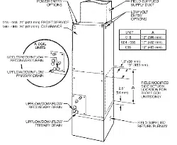
A. Upflow Installation
If return air is to be ducted through a floor, set unit on floor over
opening and use 1/8 to 1/4" (3 to 6 mm) thick fireproof resilient
gasket between duct, unit, and floor.
Side return is a field option on slope coil models. Cut opening per
dimensions. (See Fig. 1.) A field-supplied bottom closure is
required.
A07565
Fig. 1 - Slope Coil Unit in Upflew Application
B. Downflow Installation
In this application, field conversion of the evaporator is required
using accessory downflow kit along with an accessory base kit.
Use fireproof resilient gasket, 1/8 to 1/4" (3 to 6 mm) thick,
between duct, unit, and floor.
UNIT OR PROPERTY DAMAGE HAZARD
Failure to follow this caution may result in product or property
damage.
The conversion of the fan coil to downflow requires special
procedures for the condensate drains on both A-coil and slope
units. The vertical drains have an overflow hole between the
primary and secondary drain holes. This hole is plugged for all
applications except downflow, but must be used for downflow.
During the conversion process, remove the plastic cap
covering the vertical drains only and discard. Remove the plug
from the overflow hole and discard. At completion of the
downflow installation, caulk around the vertical pan fitting to
door joint to retain the low air leak performance of the unit.
NOTE: To convert units for downflow applications, refer to
Installation Instructions supplied with kit for proper installation.
For slope fan coils, use kit Part No. KFADC0201SLP. For A-coils,
use kit Part No. KFADC0401ACL. Use fireproof resilient gasket.
1/8 to 1/4" (3 to 6 mm) thick, between duct, unit, and floor.
NOTE: Gasket kit number KFAHD0101SLP is also required for
all downflow applications to maintain low air leak/low sweat
performance.
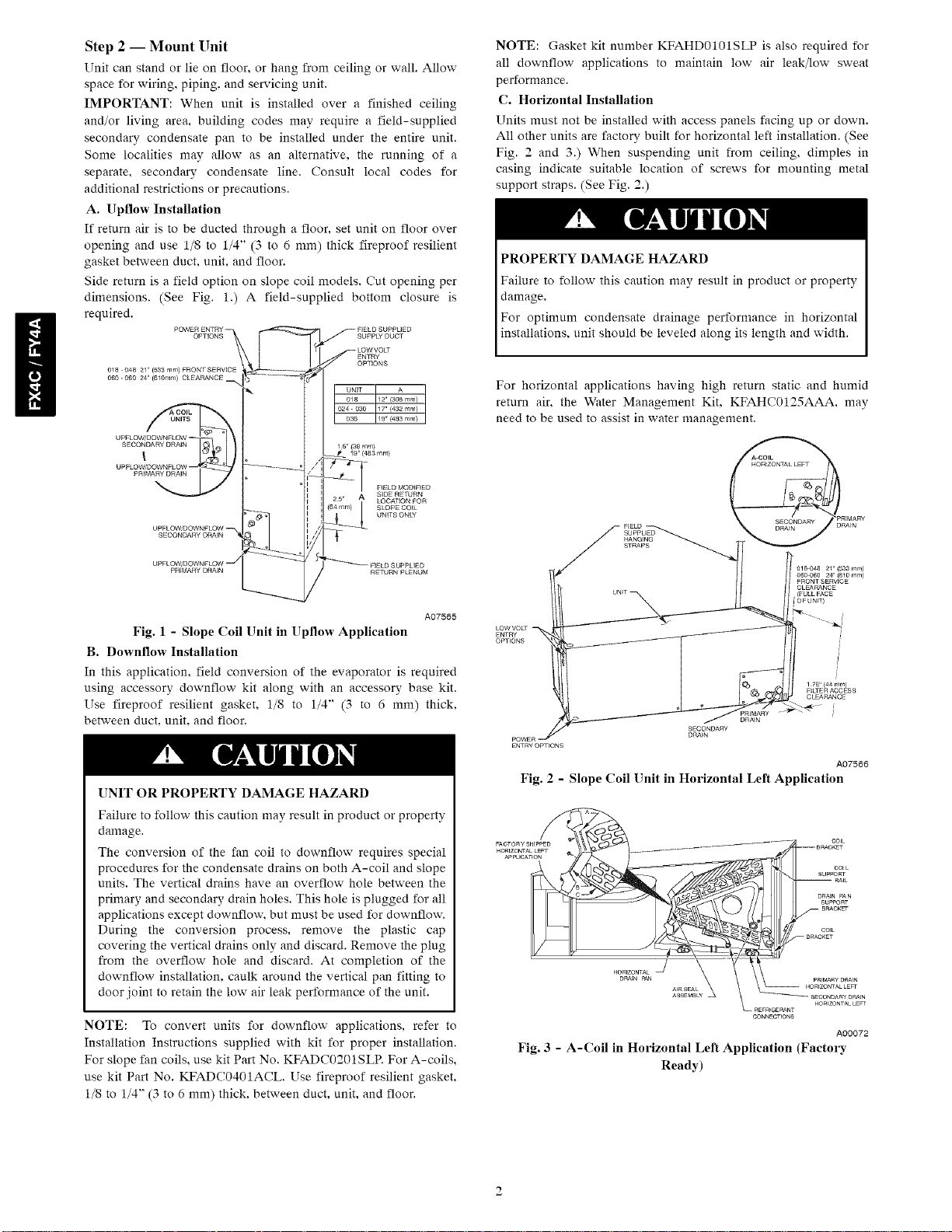
C. Horizontal Installation
Units must not be installed with access panels facing up or down.
All other units are factory built for horizontal left installation. (See
Fig. 2 and 3.) When suspending unit from ceiling, dimples in
casing indicate suitable location of screws for mounting metal
support straps. (See Fig. 2.)
PROPERTY DAMAGE HAZARD
Failure to follow this caution may result in product or property
damage.
For optimum condensate drainage performance in horizontal
installations, unit should be leveled along its length and width.
For horizontal applications having high return static and humid
return air, the Water Management Kit. KFAHC0125AAA. may
need to be used to assist in water management.
ENTRY
OPTIONS
HANGING
STRAPS
SECONDARY
DRA_N
018048 21" {833 ram)
060 060 24" (610 rnm)
FRONTSERVICE
CLEARANCE
{FULLFACE
[©FUNT
i
1 75" {44 ram)
F_LTE R ACCESS
CLEARANCE
DRA_N
A07566
Fig. 2 - Slope Coil Unit in Horizontal Left Application
cot L
SUPPORT
RAtL
DRAENPAN
SUPPORT
CONNECTIONS
A00072
Fig. 3 - A-Coil in Horizontal Left Application (Factory
Ready)
Loading ...
Loading ...
Loading ...