Loading ...
Loading ...
Loading ...
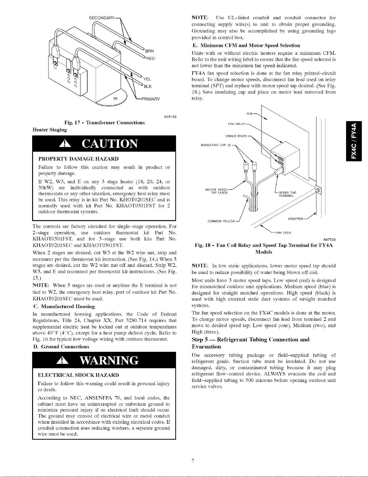
RED
NOTE: Use UL-listed conduit and conduit connector for
connecting supply wire(s) to unit to obtain proper grounding.
Grounding may also be accomplished by using grounding lugs
provided in control box.
E. Minimum CFM and Motor Speed Selection
Units with or without electric heaters require a minimum CFM.
Refer to the unit wiring label to ensure that the fan speed selected is
not lower than the minimum fan speed indicated.
FY4A fan speed selection is done at the fan relay printed-circuit
board. To change motor speeds, disconnect fan lead used on relay
terminal (SPT) and replace with motor speed tap desired. (See Fig.
18.) Save insulating cap and place on motor lead removed from
relay.
Fig. 17 - Transformer Connections
Heater Staging
A05182
PROPERTY DAMAGE HAZARD
Failure to follow this caution may result in product or
property damage.
If W2, W3, and E on any 3 stage heater (18, 20. 24, or
30kW) are individually connected as with outdoor
thermostats or any other situation, emergency heat relay must
be used. This relay is in kit Part No. KHOT0201SEC and is
normally used with kit Part No. KHAOT0301FST for 2
outdoor thermostat systems.
The controls are factory circuited for single-stage operation. For
2-stage operation, use outdoor thermostat kit Part No.
KHAOT0301FST. and for 3-stage use both kits Part No.
KHAOT0201SEC and KHAOT0301FST.
When 2 stages are desired, cut W3 at the W2 wire nut. strip and
reconnect per the thermostat kit instruction. (See Fig. 14.) When 3
stages are desired, cut the W2 wire nut off and discard. Strip W2,
W3, and E and reconnect per thermostat kit instructions. (See Fig.
15.)
NOTE: When 3 stages are used or anytime the E terminal is not
tied to W2, the emergency heat relay, part of outdoor kit Part No.
KHAOT0201SEC must be used.
C. Manufactured Housing
In manufactured housing applications, the Code of Federal
Regulations, Title 24, Chapter XX, Part 3280.714 requires that
supplemental electric heat be locked out at outdoor temperatures
above 40°F (4°C), except for a heat pump defrost cycle. Refer to
Fig. 16 for typical low voltage wiring with outdoor thermostat.
D. Ground Connections
ELECTRICAL SHOCK HAZARD
Failure to follow this warning could result in personal injury
or death.
According to NEC, ANSI/NFPA 70, and local codes, the
cabinet must have an uninterrupted or unbroken ground to
minimize personal injury if an electrical fault should occur.
The ground may consist of electrical wire or metal conduit
when installed in accordance with existing electrical codes. If
conduit connection uses reducing washers, a separate ground
wire must be used.
FAN RELAY_
A97529
Fig. 18 - Fan Coil Relay and Speed Tap Terminal for FY4A
Models
NOTE: In low static applications, lower motor speed tap should
be used to reduce possibility of water being blown off coil.
Most units have 3 motor speed taps. Low speed (red) is designed
for mismatched outdoor unit applications. Medium speed (blue) is
designed for straight matched operations. High speed (black) is
used with high external static duct systems of straight matched
systems.
The fan speed selection on the FX4C models is done at the motor.
To change motor speeds, disconnect fan lead from terminal 2 and
move to desired speed tap; Low speed (one), Medium (two), and
High (three).
Step 5 -- Refrigerant Tubing Connection and
Evacuation
Use accessory tubing package or field-supplied tubing of
refrigerant grade. Suction tube must be insulated. Do not use
damaged, dirty, or contaminated tubing because it may plug
refrigerant flow-control device. ALWAYS evacuate the coil and
field-supplied tubing to 500 microns before opening outdoor unit
service valves.
Loading ...
Loading ...
Loading ...