Loading ...
Loading ...
Loading ...
IGNITIONSWITCH
Turn the key to the START position to start the
engine. When the engine is running, let the key return
' to the ON position. To stop the engine, turn the key to
the left to the OFF position and remove it to prevent
accidental starting. See figure 6.
LIGHTSWITCH(Optional)
Push the light switch to turn on the lights. The lights
will only operate when the engine is running. See
figure 6.
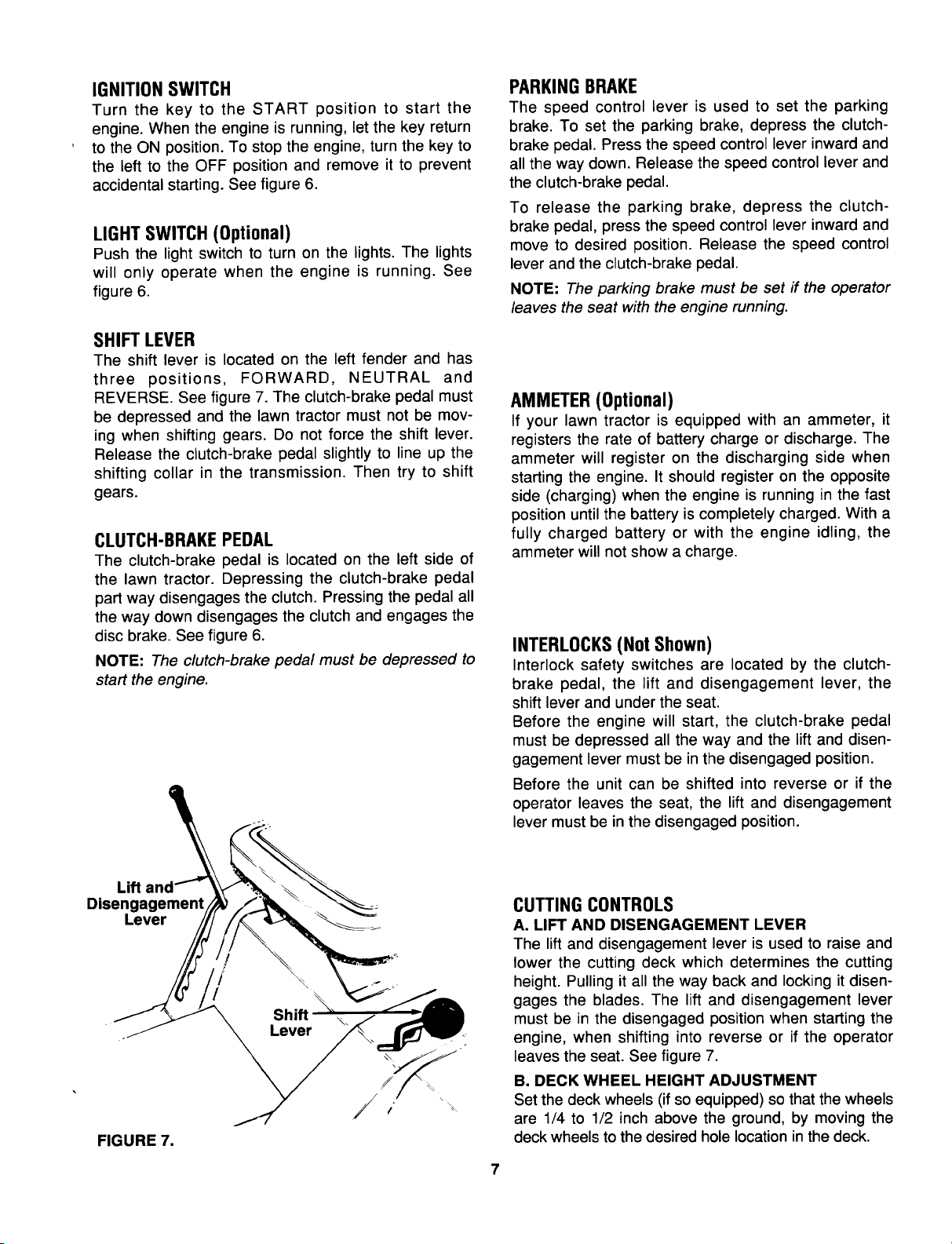
SHIFTLEVER
The shift lever is located on the left fender and has
three positions, FORWARD, NEUTRAL and
REVERSE. See figure 7. The clutch-brake pedal must
be depressed and the lawn tractor must not be mov-
ing when shifting gears. Do not force the shift lever.
Release the clutch-brake pedal slightly to line up the
shifting collar in the transmission. Then try to shift
gears.
CLUTCH-BRAKEPEDAL
The clutch-brake pedal is located on the left side of
the lawn tractor. Depressing the clutch-brake pedal
part way disengages the clutch. Pressing the pedal all
the way down disengages the clutch and engages the
disc brake. See figure 6.
NOTE: The clutch-brake pedal must be depressed to
start the engine.
PARKINGBRAKE
The speed control lever is used to set the parking
brake. To set the parking brake, depress the clutch-
brake pedal. Press the speed control lever inward and
all the way down. Release the speed control lever and
the clutch-brake pedal.
To release the parking brake, depress the clutch-
brake pedal, press the speed control lever inward and
move to desired position. Release the speed control
lever and the clutch-brake pedal.
NOTE: The parking brake must be set if the operator
leaves the seat with the engine running.
AMMETER(Optional)
If your lawn tractor is equipped with an ammeter, it
registers the rate of battery charge or discharge. The
ammeter will register on the discharging side when
starting the engine. It should register on the opposite
side (charging) when the engine is running in the fast
position until the battery is completely charged. With a
fully charged battery or with the engine idling, the
ammeter will not show a charge.
INTERLOCKS(NotShown)
Interlock safety switches are located by the clutch-
brake pedal, the lift and disengagement lever, the
shift lever and under the seat.
Before the engine will start, the clutch-brake pedal
must be depressed all the way and the lift and disen-
gagement lever must be in the disengaged position.
Before the unit can be shifted into reverse or if the
operator leaves the seat, the lift and disengagement
lever must be in the disengaged position.
Lift
Disengagement
Lever
FIGURE 7.
CUTTING CONTROLS
A. LIFT AND DISENGAGEMENT LEVER
The lift and disengagement lever is used to raise and
lower the cutting deck which determines the cutting
height. Pulling it all the way back and locking it disen-
gages the blades. The lift and disengagement lever
must be in the disengaged position when starting the
engine, when shifting into reverse or if the operator
leaves the seat. See figure 7.
B. DECK WHEEL HEIGHT ADJUSTMENT
Set the deck wheels (if so equipped) so that the wheels
are 1/4 to 1/2 inch above the ground, by moving the
deck wheels to the desired hole location in the deck.
Loading ...
Loading ...
Loading ...