Loading ...
Loading ...
Loading ...
8. Depress the clutch-brake pedal forward
stop on the clutch-brake pedal asser
solidly against the underside of the fram_
9. Remove the hairpin clip and flat washer
rod attached to the back of the spee(
lever.
until the
lbly hits
from the
I control
10. Place the speed control lever in parki_
position.
11. Thread the ferrule on the rod until the fer
into the bottom end of the slot in the sp
trol lever, then thread the ferrule down o
one full turn (to shorten).
12. Position speed control lever as follows:
_g brake
"ule slips
._edcon-
1the rod
a. 7-speed units: Place speed control lever in
second position.
b. 5-speed units: Place speed control lever in
first position.
13. Place ferrule into speed control lever _;Iot, and
secure with flat washer and hairpin clip. Release
the clutch-brake pedal.
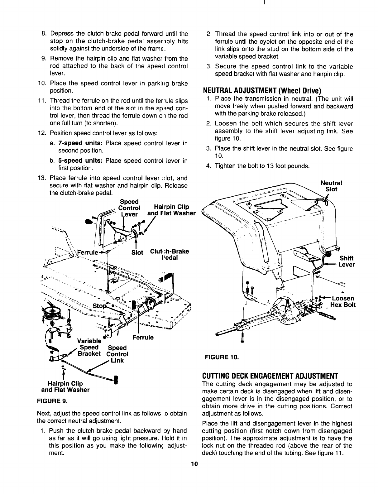
Speed
Control Hal rpin Clip
_" Lever and Flat Washer
Slot Clut,
,h-Brake
I'edal
Ferrule
Speed
Control
Link
Hairpin Clip
and Flat Washer
FIGURE 9.
Next, adjust the speed control link as follows o obtain
the correct neutral adjustment.
1. Push the clutch-brake pedal backward _y hand
as far as it will go using light pressure. Itold it in
this position as you make the followin( adjust-
ment.
10
2. Thread the speed control link into or out of the
ferrule until the eyelet on the opposite end of the
link slips onto the stud on the bottom side of the
variable speed bracket.
3. Secure the speed control link to the variable
speed bracket with flat washer and hairpin clip.
NEUTRALADJUSTMENT (Wheel Drive)
1. Place the transmission in neutral. (The unit will
move freely when pushed forward and backward
with the parking brake released.)
2. Loosen the bolt which secures the shift lever
assembly to the shift lever adjusting link. See
figure 10.
3. Place the shift lever in the neutral slot. See figure
10.
4. Tighten the bolt to 13 foot pounds.
Neutral
Slot
Shift
Lever
Hex Bolt
FIGURE 10.
CUTTING DECKENGAGEMENTADJUSTMENT
The cutting deck engagement may be adjusted to
make certain deck is disengaged when lift and disen-
gagement lever is in the disengaged position, or to
obtain more drive in the cutting positions. Correct
adjustment as follows.
Place the lift and disengagement lever in the highest
cutting position (first notch down from disengaged
position). The approximate adjustment is to have the
lock nut on the threaded rod (above the rear of the
deck) touching the end of the tubing. See figure 11.
Loading ...
Loading ...
Loading ...