Loading ...
Loading ...
Loading ...
Steering
Wheel Ca
Hex
Bolt
Steering
Shaft
FIGURE 1.
Screws
Seat
Pivot
Bracket
1
FIGURE 2.
\
Steering
Bellow
Hex Nuts
Cupped
Washers
Machine
Screws
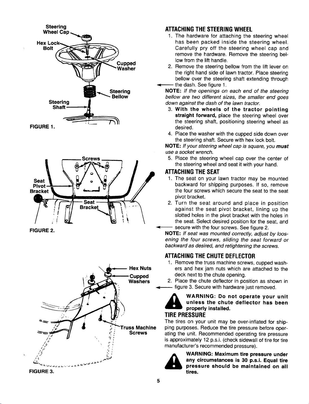
ATTACHINGTHE STEERING WHEEL
1. The hardware for attaching the steering wheel
has been packed inside the steering wheel.
Carefully pry off the steering wheel cap and
remove the hardware. Remove the steering bel-
low from the lift handle.
2. Remove the steering bellow from the lift lever on
the right hand side of lawn tractor. Place steering
bellow over the steering shaft extending through
the dash. See figure 1.
NOTE: If the openings on each end of the steering
bellow are two different sizes, the smaller end goes
down against the dash of the lawn tractor.
3. With the wheels of the tractor pointing
straight forward, place the steering wheel over
the steering shaft, positioning steering wheel as
desired.
4. Place the washer with the cupped side down over
the steering shaft. Secure with hex lock bolt.
NOTE: If your steering wheel cap is square, you must
use a socket wrench.
5. Place the steering wheel cap over the center of
the steering wheel and seat it with your hand.
ATTACHINGTHE SEAT
1. The seat on your lawn tractor may be mounted
backward for shipping purposes. If so, remove
the four screws which secure the seat to the seat
pivot bracket.
2. Turn the seat around and place in position
against the seat pivot bracket, lining up the
slotted holes in the pivot bracket with the holes in
the seat. Select desired position for the seat, and
secure with the four screws. See figure 2.
NOTE: If seat was mounted correctly, adjust by loos-
ening the four screws, sliding the seat forward or
backward as desired, and retightening the screws.
ATTACHINGTHE CHUTE DEFLECTOR
1. Remove the truss machine screws, cupped wash-
ers and hex jam nuts which are attached to the
deck next to the chute opening.
2. Place the chute deflector in position as shown in
figure 3. Secure with hardware just removed.
WARNING: Do not operate your unit
unless the chute deflector has been
properly installed.
TIREPRESSURE
The tires on your unit may be over-inflated for ship-
ping purposes. Reduce the tire pressure before oper-
ating the unit. Recommended operating tire pressure
is approximately 12 p.s,i, (check sidewall of tire for tire
manufacturer's recommended pressure).
&
WARNING: Maximum tire pressure under
any circumstances is 30 p.s.i. Equal tire
pressure should be maintained on all
tires.
5
Loading ...
Loading ...
Loading ...