Loading ...
Loading ...
Loading ...
ENGLISH
6
Transporting the Planer (Fig. A)
WARNING: For your own safety, it is recommended
that two people carry this machine or serious injury
couldresult.
When moving your planer, carry it either by the side
carrying handles
2
or by the handles
3
at the base of
theplaner.
Bench Mounting (Fig. A)
To facilitate bench mounting, two different sized holes
4
are provided on the four corners of your planer. If mounting
the planer with bolts, use the larger holes. If mounting the
planer with nails or screws, use the smaller holes. It is not
necessary to use both sets ofholes.
Always mount your planer firmly to prevent movement. To
enhance the tool’s portability, it can be mounted to a piece
of 1/2" (12.7mm) or thicker plywood which can then be
clamped to your work support or moved to other job sites
andreclamped.
NOTE: If you elect to mount your planer onto a piece
of plywood, make sure that the mounting screws don’t
protrude from the bottom of the wood. The plywood must
sit flush on the worksupport.
CAUTION: The mounting surface should not be
warped or otherwiseuneven.
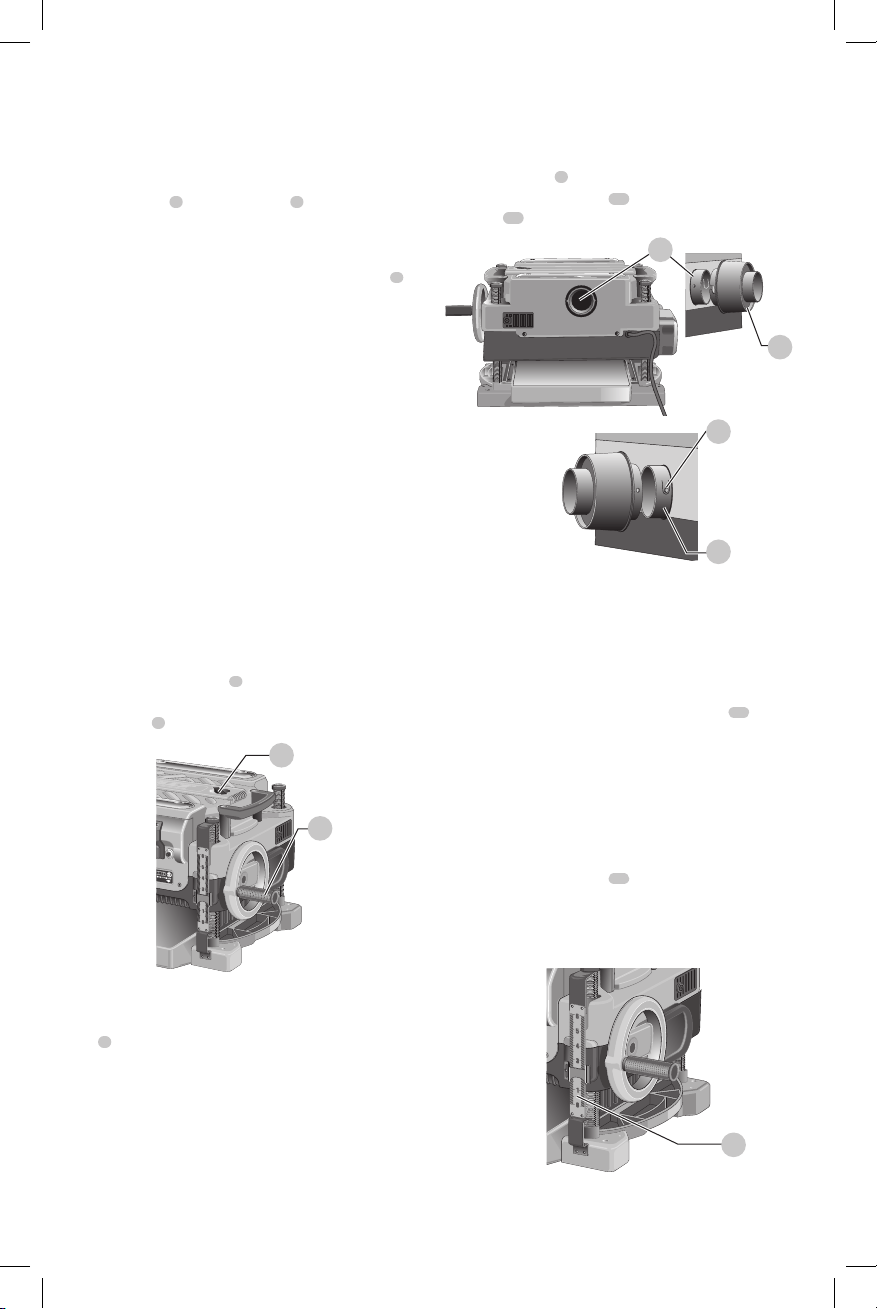
To Attach the Depth Adjustment Crank
Handle (Fig. E)
1. Remove the screw located in the crank handleshaft.
2. Insert the crank handle
5
over theshaft.
3. Secure in place with the screw and
T-wrench
8
provided.
Fig. E
5
8
Dust Ejection Ports (Fig. F)
Your planer comes with a dust ejection port. The round
port
9
as shown in Figure. F is for use with a 4" (100mm)
dust collectorhose.
To Set Up Dust Ejection (Fig. F)
WARNING: Do not operate your planer without
the dust ejection port locked into place. Do not
insert anything into the dust ejection chute
unless the planer is unplugged and you are
clearing a clog or obstruction in the unit. Do not
get your face or eyes near the dust ejection port
when the planer is in operation. Serious injury
couldresult.
WARNING: Chips are ejected at significant velocity.
Keep hands and face clear of dust ejectionport.
1. Select the port
9
.
2. Depress the lock button
11
on the chip ejection
chute
10
.
Fig. F
11
10
10
9
3. Slide the notches in the dust port over the pins on the
chip ejectionchute.
4. Rotate the port until the button engages the dust
ejection chute and locks inplace.
To Remove the Dust Ejection Port
(Fig. F)
1. Use the T-wrench to depress the lock button
11
on the
dustchute.
2. Twist the port until the pins are disengaged from the
notches on theport.
3. Pull the dust ejection port off of the dustchute.
Depth Adjustment (Fig. G)
Depth Adjustment Scale (Fig. G)
The depth adjustment scale
14
, located on the right front
of your planer, indicates the finished thickness of your
workpiece. One rotation of the depth adjustment crank
is equal to 1/16" (1.6mm), half rotation is equal to 1/32"
(0.8mm),etc.
Fig.G
14
Loading ...
Loading ...
Loading ...