Loading ...
Loading ...
Loading ...

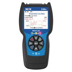
Scan Tool Controls
DISPLAY FUNCTIONS
4
1. I/M MONITOR STATUS field - Identifies the I/M Monitor status area.
2. Monitor icons - Indicate which Monitors are supported by the
vehicle under test, and whether or not the associated Monitor has
run its diagnostic testing (Monitor status). A solid green icon
indicates the associated Monitor has completed its diagnostic
testing. A flashing red icon indicates that the vehicle supports the
associated Monitor, but the Monitor has not yet run its diagnostic
testing.
3.
Vehicle icon - When visible, indicates that the Scan Tool is
being powered through the vehicle’s DLC connector.
4.
Link icon - When visible, indicates the Scan Tool is
communicating with the vehicle’s computer.
5.
Computer icon - When visible, indicates the Scan Tool is linked
to a personal computer.
6. DTC Display Area - Displays the Diagnostic Trouble Code (DTC)
number. Each fault is assigned a code number that is specific to that
fault. The DTC number is color-coded as follows:
RED - Indicates the currently displayed DTC is a STORED or
PERMANENT DTC.
YELLOW - Indicates the currently displayed DTC is a PENDING
DTC.
GREEN - In cases where no codes are retrieved, a “No DTCs
are presently stored in the vehicle’s computer” message is
shown in green.
7. Code Number Sequence - The Scan Tool assigns a sequence
number to each DTC that is present in the computer’s memory,
starting with “1.” This number indicates which code is currently
displayed. Code number “1” is always the highest priority code, and
the one for which “Freeze Frame” data has been stored.
If “1” is a “Pending” code, there may or may not be “Freeze
Frame” data stored in memory.
8. Code Enumerator - Indicates the total number of codes retrieved
from the vehicle’s computer.
9. Test Data Display Area - Displays DTC definitions, Freeze Frame
data and other pertinent test information messages.
10. SYSTEM icon - Indicates the system with which the code is
associated:
MIL icon ABS icon SRS icon
11. FREEZE FRAME icon - Indicates that there is Freeze Frame data
from “Priority Code” (Code #1) stored in the vehicle’s computer
memory.
12. Code type - Indicates the type of code being displayed; Generic
Stored, Generic Pending, Generic permanent, etc.
Loading ...
Loading ...
Loading ...