
Table of Contents
i
ABOUT THE SCAN TOOL
SAFETY FIRST! ....................................................................... 1
CONTROLS AND INDICATORS .............................................. 2
DISPLAY FUNCTIONS ............................................................ 3
INITIAL ADJUSTMENTS .......................................................... 5
USING THE SCAN TOOL
CODE RETRIEVAL PROCEDURE .......................................... 6
THE SYSTEM MENU ............................................................... 10
VIEWING OEM ENHANCED DTCs (except Ford/Mazda)........ 11
VIEWING OEM ENHANCED DTCs (Ford/Mazda only) ........... 12
VIEWING ABS DTCs ................................................................ 13
ERASING DIAGNOSTIC TROUBLE CODES (DTCs) .............. 15
ABOUT REPAIRSOLUTIONS 2® ............................................ 16
CONNECTING TO BLUETOOTH / WIFI ................................. 17
LIVE DATA MODE
VIEWING LIVE DATA .............................................................. 18
CUSTOMIZING LIVE DATA (PIDs) ......................................... 19
ADDITIONAL FUNCTIONS
SYSTEM TEST MENU ............................................................. 21
VIEWING VEHICLE INFORMATION ....................................... 24
BATTERY/ALTERNATOR TEST ............................................. 26
VIEWING THE FIRMWARE VERSION .................................... 28
THE TOOL LIBRARY ............................................................... 28
ADJUSTMENTS AND SETTINGS ........................................... 30
WARRANTY AND SERVICING
LIMITED ONE YEAR WARRANTY .......................................... 33
SERVICE PROCEDURES ....................................................... 33
About the Scan Tool
SAFETY FIRST
1
SAFETY FIRST!
This manual describes common test procedures used by experienced
service technicians. Many test procedures require precautions to avoid
accidents that can result in personal injury, and/or damage to your
vehicle or test equipment. Always read your vehicle's service manual
and follow its safety precautions before and during any test or service
procedure. ALWAYS observe the following general safety precautions:
When an engine is running, it produces carbon monoxide, a
toxic and poisonous gas. To prevent serious injury or death
from carbon monoxide poisoning, operate the vehicle ONLY
in a well-ventilated area.
To protect your eyes from propelled objects as well as hot
or caustic liquids, always wear approved safety eye
protection.
When an engine is running, many parts (such as the coolant
fan, pulleys, fan belt etc.) turn at high speed. To avoid serious
injury, always be aware of moving parts. Keep a safe distance
from these parts as well as other potentially moving objects.
Engine parts become very hot when the engine is running.
To prevent severe burns, avoid contact with hot engine
parts.
Before starting an engine for testing or trouble-shooting, make
sure the parking brake is engaged. Put the transmission in
park (for automatic transmission) or neutral (for manual
transmission). Block the drive wheels with suitable blocks.
Connecting or disconnecting test equipment when the
ignition is ON can damage test equipment and the vehicle's
electronic components. Turn the ignition OFF before
connecting the Code Reader to or disconnecting the Code
Reader from the vehicle’s Data Link Connector (DLC).
To prevent damage to the on-board computer when taking
vehicle electrical measurements, always use a digital
multimeter with at least 10 MegOhms of impedance.
The vehicle's battery produces highly flammable hydrogen
gas. To prevent an explosion, keep all sparks, heated items
and open flames away from the battery.
Don't wear loose clothing or jewelry when working on an
engine. Loose clothing can become caught in the fan,
pulleys, belts, etc. Jewelry is highly conductive, and can
cause a severe burn if it makes contact between a power
source and ground.
N
L
D
R
P
About the Scan Tool
CONTROLS AND INDICATORS
2
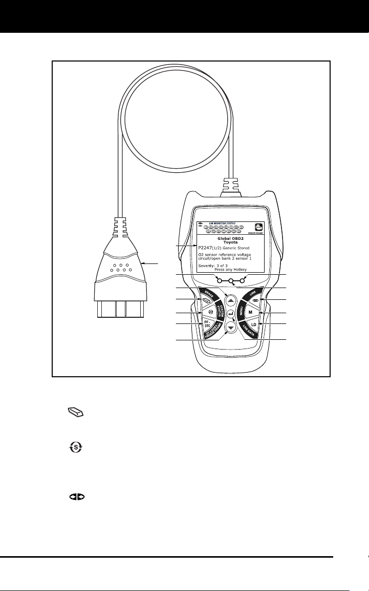
CONTROLS AND INDICATORS
Figure 1. Controls and Indicators
See Figure 1 for the locations of items 1 through 14, below.
1.
ER
ASE button - Erases Diagnostic Trouble Codes (DTCs) an
d
"Freeze Fram
e" data from your vehicle's computer, and resets
Monitor status.
2.
SYSTEM MENU button – When pressed, displays the System
Menu.
3. DTC/FF button – Displays the DTC View scre
en and/or scrolls the
LCD dis
play to view DTCs and Freeze Frame data.
4.
LI
NK button - When connected to a vehicle, links the Scan
Tool to the vehicle’s PCM.
14
8
6
5
4
11
12
2
3
9
7
10
13
1
About the Scan Tool
DISPLAY FUNCTIONS
3
5. M (Menu) button – When pressed, displays the Main Menu.
6. LD
button – When pressed while linked to a vehicle, places the
Scan Tool in Live
Data mode.
7. UP butto
n – When in ME
NU mode, scrolls UP through the
menu optio
ns. When LINKED to a vehicle, scrolls UP through the
current display screen to display any additional data.
8.
ENTER button - When in Menu mode, confirms the selected
option or value.
9.
DO
WN button - When in MENU mode, scrolls down throug
h the
menu options.
When LINKED to a vehicle, scrolls down through the
current display screen to display any additional data.
10. GREEN LED - Indicates that all engine systems are running
normally (all Monitors on the vehicle are active and performing
their
diag
nostic testing, and no DTCs
are present).
11. YEL
LOW LED - Indicates there is a possible problem. A “Pending
”
DT
C is present and/or some of the vehicle's emission monitors have
not run their diagnostic testin
g.
12. RE
D LED - Indicates there is a problem in one or more of the
vehicle's systems. The red LED is also used to show that DTC(s)
are present. DTCs are shown on the Scan Tool’s LCD display. In
this case, the Malfunction Indicator (“Check Engine”) lamp
on the
vehic
le's instrument panel
will light steady on.
13. Di
splay - Displays test results, Scan Tool functions and Monitor status
information. See DISPLAY FUNCTIONS, below, for details.
14. CABLE - Connects the Scan Tool to the vehicle's Data Link Connecto
r
(DLC
).
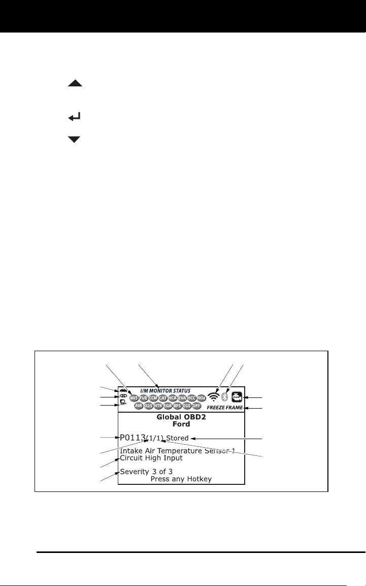
DISPLAY FUNCTIONS
Figure 2. Display Functions
See Figure 2 for the locations of items 1 through 15, below.
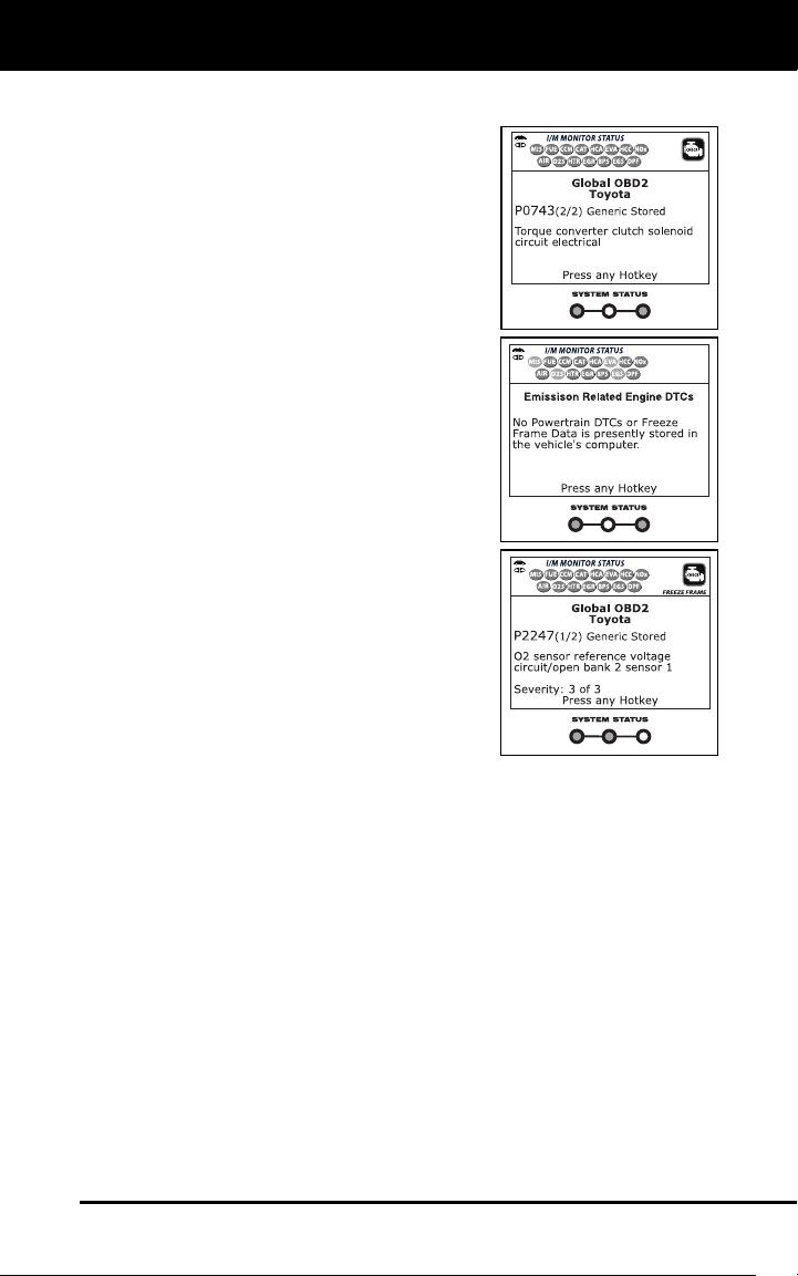
1. I/M MONITOR STATUS field - Identifies the I/M
Monitor status area.
4
3
2
5
7
6
114
10
11
12
8
9
13
15

About the Scan Tool
DISPLAY FUNCTIONS
4
2. Monitor icons - Indicate which Monitors are supported by the
vehic
le under test, and whether or not the associated Monitor has
run its diagnostic testing (Monitor status). A solid green icon
indicates the associated Monitor has completed its diagnostic
testing. A flashing red icon indicates that the vehicle supports
the
assoc
iated Monitor, but the Monitor has not yet run its diagn
ostic
testing.
3.
Vehicle icon - When visible, indicates that the scan tool is being
powered through the vehicle’s DLC connector.
4.
Link icon - When visible, indicates the scan tool is
communicating
with the vehicle’s computer.
5.
Computer icon - When visible, indicates the scan tool is linked
to a personal computer.
6. DTC Display Area - Displays the Diagnostic Trouble Code (DTC)
number. Each fault is assigned a code number that is specific to
that
fault. The DT
C number is color-coded as follow
s:
RED - Indicates the currently displayed DTC is a STORED or
PE
RMANENT DTC.
YELLOW - Indicates the currently displayed DTC is a PENDING
DT
C.
GREEN - In cases where no codes are retrieved, a “No DTCs
are presently stored in the
vehicle’s comp
uter” message is
shown in green.
7. Co
de Number Sequence - The scan tool assigns a sequence
number to each DTC that is present in the computer’s me
mory,
starting with “1.” This number indicates wh
ich code is currently
displayed. Code number “1” is always the highest priority co
de, and
the one for whic
h “Freeze Frame” data has bee
n stored.
If “1” is a “Pen
ding” code, there may or may not be “Freeze
Frame” data stored in memory.
8. Code Enumerator - Indicates the total number of codes retrieved
from the vehicle’
s computer.
9. Test Data Disp
lay Area - Displays DTC definitions, Freeze Frame
data and other pertinent test information messa
ges.
10. SY
STEM icon - Indicates the system with which the co
de is
assoc
i
ated:
MIL icon ABS icon
11. FREEZE FRAME icon - Indicates that there is Freeze Frame data
from “Priority Code” (Code #1) stored in the vehicle’s co
mputer
memory.
12. Co
de type - Indicates the type of code being displayed;
Generic
Stored, Gen
eric Pending, Generic permanent
, etc.
13. Severity - Indic
ates the level of severity for the priority code (c
ode
number “1”), as
follo
ws:

About the Scan Tool
INITIAL ADJUSTMENTS
5
1 - Service should be scheduled and repairs made when
convenient. This DTC typically has no immediate threat to
essential system components in the short term.
2 - Repair immediately if drivability issues are present. Threat to
essential system components if not repaired as soon as possible.
3 - Stop and repair vehicle immediately to prevent interrelated
failures. Harmful and damaging to essential system components.
14.
Bluetooth icon – Indicates communication status with a
compatib
le Innova mobile application (please visit
www.innova.com/apps for more information). A solid blue icon
indicates an active Bluetooth connection has been established. A
solid grey icon indicates Bluetooth is not connected.
15.
WiFi icon – Indicates WiFi communication status. When ON,
ind
icates the scan tool is linked to a WiFi network. When OFF,
indicates there is no WiFi connection.
INITIAL ADJUSTMENTS
The first time the unit is connected to a vehicle, you must select the
desired display language (English, French or Spanish) and unit of
measurement (USA or Metric) as follows:
1. Select the desired display language, then press ENTER
.
The Select Unit screen displays.
2. Select the desir
ed unit of measurement, then press ENTER
.
After the initial language and unit of measurement selections
are performed, these, as well as other settings, can be
changed as desired. Proceed to “ADJUSTMENTS AND
SETTINGS” on page 29 for further instructions.
Using the Scan Tool
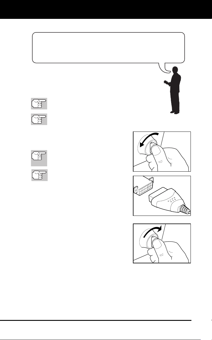
CODE RETRIEVAL PROCEDURE
6
CODE RETRIEVAL PROCEDURE
Never replace a part based only on the DTC definition.
Each DTC has a set of testing procedures, instructions
and flow charts that must be followed to confirm the
location of the problem. Always refer to the vehicle's
service manual for detailed testing instructions.
Check your vehicle thoroughly before performing
any test.
ALWAYS observe safety precautions whenever working on a
vehicle.
1. Turn the igniti
on off.
2. Locate the veh
i
cle's 16-pin Data Link
C
onnector (D
LC).
Some DLCs ha
ve a plastic cover
that must be removed before
connecting the Scan Tool.
If the Scan Tool is ON, turn it OFF
BEFORE connecting to the DLC.
3. Connect the Scan Tool to the vehicle's
DLC. The cable connector is keyed and
will only fit one way.
If you have problems connecting the
cable
connector to the DLC, rotate
the connector 1
80°.
I
f you still have problems, check th
e
DL
C on the vehicle and on the Scan
Tool.
4. Turn the
ignition on. DO NOT start the
engine.
5. When the S
can Tool is properly
connected to the vehicl
e’s DLC, the
S
can Tool will automatically turn ON
.
If the unit does not power on automatically, it may indicate there
is no power pre
sent at the vehicle’s DLC conn
ector. Check the
fuse panel a
nd replace any burn
ed-out fuses.
If replacing the fuse(s) does not correct the problem, consult
your vehic
le’s repair manual to identify the
proper computer
(PCM) fuse/circ
uit, and perform any necessary repairs befor
e
proceeding.
Retrieving and using Diagnostic Trouble Codes (DTCs) for
troubleshooting vehicle operation is only one part of an
overall diagnostic strategy.
Using the Scan Tool
CODE RETRIEVAL PROCEDURE
7
6. The Scan Tool automatically starts a check of the vehicle’s
computer to determine which type of communication
protocol it is
using. W
hen the Scan Tool identifies the computer’s communication
protocol, a communicati
on link is established.
A
PROTOCOL is a set of rules and procedures for regulating data
transmission between computers, and between testing equipment
and computers. As of this writing, five different types of protocols
(ISO 9141, Keyword 2000, J1850 PWM, J1850 VPW and CAN)
are in use by vehicle manufacturers.
If the Scan Tool fails to link to the vehicle’s computer, a
“Co
mmunication Error” message shows.
- Ensure your vehicle is OBD2 comp
liant.
-
Verify the connection at the DLC, and verify the ignition is ON
.
-
Turn the ignition OFF, wait 5 seconds, then back ON to reset
the computer.
- Press LINK
to continue.
If the Scan Tool cannot link to the vehicle’s computer after three
attempts, the message “Contac
t Technical Support” displa
ys.
- Pr
ess the SYSTEM MENU
button to return to the System
Menu.
- Turn the ignition off, and discon-
nect the Scan Tool.
- Contact Technical Support for as-
sistance.
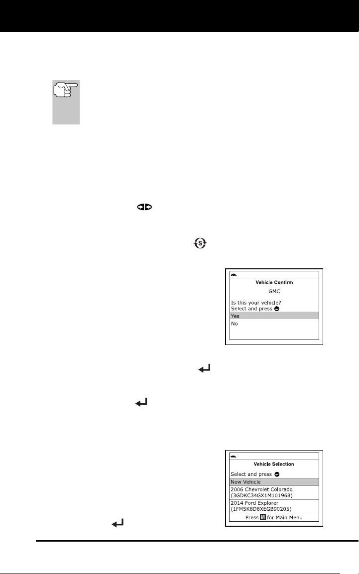
7. If the Scan Tool can decode the Vehicle
Identification Number (VIN) for the
vehicle under test, the Confirm Vehicle
screen displays
.
If the information shown is correct for the vehicle under test,
select Ye
s, then press ENTER
. Proceed to step 10.
If the information shown is not correct for the vehicle under test,
or if you wish t
o manually select the vehicle, select No, then
press ENTER
. Proceed to step 8.
If the Scan Tool cannot decode the Vehicle Identification
Number (VIN)
for the vehicle under test, the Select Vehicl
e
screen dis
plays. Proceed to step 8
.
8. When No is se
lected from the Vehicle
information screen, the Select Vehicle
screen displays. The Select Vehicle
screen lists the three most recently
tested vehic
l
es.
To use a previously tested vehicle,
select
the desired vehicle, then press
ENTER
. Proceed to step 10.
Using the Scan Tool
CODE RETRIEVAL PROCEDURE
8
To select a new vehicle, choose
New Vehicle, then press ENTER
. Proceed to step 9.
9. When New Vehicle is chosen from
the
Select Veh
icle screen, the Select Make
screen displa
ys.
Select the desired vehicle make,
then press EN
TER
to continue.
-
The Vehicle Information screen
displays.
If the information shown is correct for the vehicle under test,
select Ye
s, then press ENTER
. Proceed to step 10.
If the information shown is not correct for the vehicle under test,
or if you
wish to reselect the vehicle, select No, then press
ENTER
to
return to the Select Make screen.
10. After approxima
tely 10~60 seconds, the Scan Tool will retrieve and
display any Diagnostic Trouble Codes, Monitor Status and Freeze
Frame Data retrieved from the vehicle’s comput
er memory.
The Scan Tool will display a code only if codes are present. If no
co
des are present, the message “No Powertrain DTCs or Freeze
Frame Data presently stored in the vehicle’s computer” displays.
The Scan Tool is capable of retrieving and storing up to 32 codes in
memory, for immediate or later viewing.
11. Refer to DISPLAY FU
NCTIONS on page 3 for a description of
disp
lay element
s.
In the case of long c
ode
definitions, or when viewing
Freeze Frame Data, a small arrow
is shown in the upper/lower right-
hand corner of the Scan Tool
display area to indicate the
presence of additional information.
If a definition for the currently displayed code is not available,
an advisory message shows.
12. Read and interpret Diagnostic Trouble Codes/system condition
using the display and the green, yellow and red
LEDs.
The green, yellow and red L
EDs are used (with the LCD
display) as visual aids to make it easier to determine engine
system conditions.
Green LED – Indicates that all engine
systems are “OK” and operatin
g
n
ormally. All monitors supported by
the vehicle have run and pe
rformed
th
eir diagnostic testing, and no troubl
e
co
des are present. All Monitor icons
will be solid.
Using the Scan Tool
CODE RETRIEVAL PROCEDURE
9
Yellow LED - Indicates one of the following conditions:
A.
A PENDING CODE IS PRESENT – If
the yellow LED is illuminated, it may
indicate a Pending code is present.
Check the display for confirmation. A
Pending code is confirmed by the
presence of a numeric code and the
word PENDING.
B. MONITOR NOT RUN STATUS – If
the display shows a zero (indicating
there are no DTC’s present in the
vehicle’s computer memory), but the
yellow LED is illuminated, it may be
an indication that some of the
Monitors supported by the vehicle
have not yet run and completed their
diagnostic testing. Check the display
for confirmation. All Monitor icons that
are blinking have not yet run and
completed their diagnostic testing; all
Monitor icons that are solid have run
and completed their diagnostic testing.
Red LED - Indicates there is a
pro
blem with one or more of the
vehicle's systems. The red LED
is
a
lso used to show that DTC(s) ar
e
p
resent. In this case, the Malfuncti
on
In
dicator (Check Engine) lamp on th
e
v
ehicle's instrument panel will ligh
t
s
teady on.
DTC’s that start with “P0”, “P2”
and
some “P3” are considered Generic
(Universal). All
Generic
DTC definitions are the same on all OBD2 equipped
vehicles. The Scan Tool automatically displays the code
definitions (if available) for Generic
DTC’s.
DTC’s that start with “P1” and some “P3” are Manufacturer
specific
codes and their code definitions vary with each vehicl
e
manufa
ctu
rer.
13. If more than one DT
C was retrieved, and to view Freeze Frame
Data, press and release DTC/FF, as necessary
.
Each time DTC/FF
is pressed and released, the Scan Tool will
scroll and d
isplay the next DTC in sequence until all DTCs in
its
memory have display
ed.
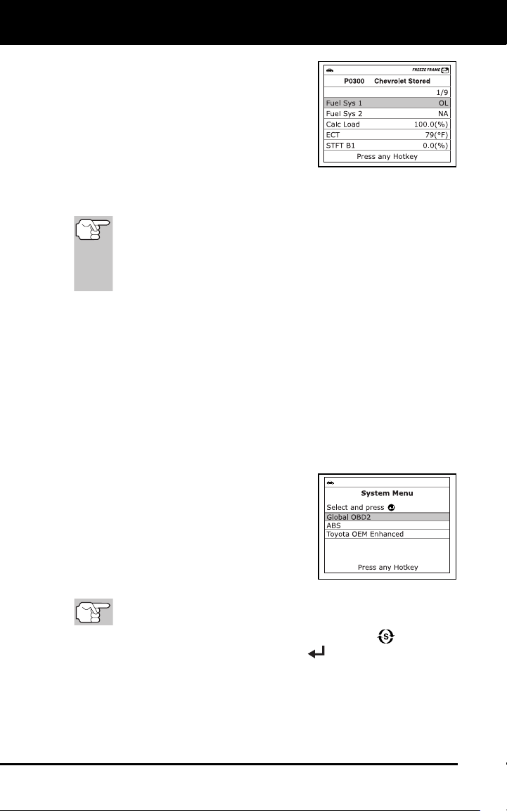
Freeze Frame data (if available) will display after DTC #1.
Using the Scan Tool
THE SYSTEM MENU
10
In OBD2 systems, when an emis-
sions-related engine malfunction oc-
curs that causes a DTC to set, a re-
cord or snapshot of engine conditi
ons
at the t
ime that the malfunction
occurred is also saved in the vehicle’
s
com
puter memory. The record saved
is called Freeze Frame data. Saved
engine conditions include, but are not
limited to: engine speed, open or closed loop operation, fuel syst
em
c
ommands, coolant temperature, calculated load value,
fuel
pre
ssure, vehicle speed, air flow rate, and intake manifold pressure
.
If more than
one malfunction is present that causes more than
one DTC to be set, only the code with the highest priority will
contain Freeze Frame data. The code designated “01” on the
Scan Tool display is referred to as the PRIORITY code, and
Freeze Frame data always refers to this code. The priority
code is also the one that has commanded the MIL on.
14. When the last retrieved DTC has been displayed and DTC/FF is
pressed, the Scan Tool
returns to the “Priority” Code.
15. Determin
e engine system(s) condition by viewing the displa
y for any
retrieved
Diagnostic Trouble Codes, code definitions and Freeze
Frame data, and interpreting the green, yellow and red LE
Ds.
If DTC’s were retrieved and you are going to perform the repairs
yourself, proceed by consulting the Vehicle’s Service Repair
Manual for testing instructions
, testing procedures, and flow
charts related to retrieved code(s).
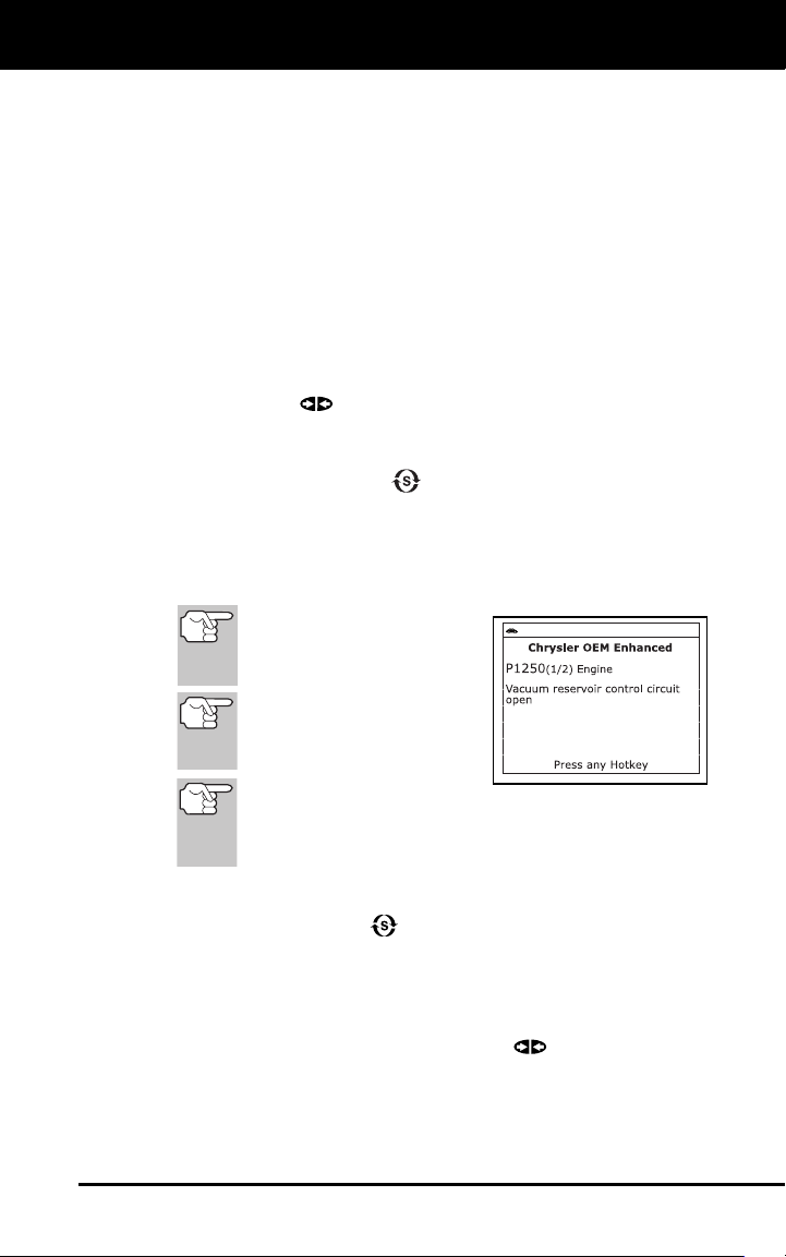
THE SYSTEM MENU
The System Menu provides the ability to
retrieve “enhanced” DTCs and Anti-Lock
Brake System (ABS) DTCs for most Audi,
BMW, Chrysler/Jeep, Ford/Mazda, GM/Isuzu,
Hyundai, Kia, Mercedes Benz, Toyota/Lexus
and Volkswagen vehicles. The types of
enhanced data available depends on the
vehicle make. You can also return to the
Global OBD2 mode.
Depending on the vehicle under test, some features and
functions may not be available.
To access the System Menu, press SYSTEM MENU . Select the
desired option, then press ENTER
to view the selected
informati
on.
To vi
ew ABS DTCs: Select ABS from the System Menu. Refer to
VIEWING ABS DTCson page 13 to view ABS DTCs for your vehicle.
To view OEM enhanced DTCs: Select OEM Enhanced from the
System Menu. Refer to VIEWING OEM ENHANCED DTCs on page 11
to view OEM enhanced DTCs for your vehicle.
Using the Scan Tool
VIEWING OEM ENHANCED DTCs (except Ford/Mazda)
11
VIEWING OEM ENHANCED DTCs (except Ford/Mazda)
When (make) OEM Enhanced is chosen from the System Menu, the
Scan Tool retrieves OEM enhanced DTCs from the vehicle’s computer.
1. A “One moment please” message displays while the Scan Tool
retrieves the selected DT
Cs.
If the Scan Tool fails to link to the vehicle’s computer, a
“Co
mmunication Error” message shows.
- Ensure your vehicle is OBD2 co
mpliant.
-
Verify the connection at the DLC, and verify the ignition is ON
.
-
Turn the ignition OFF, wait 5 seconds, then back ON to reset
the computer.
- Press LINK
to continue.
If the Scan Tool cannot link to the vehicle’s computer after three
attempts, the message “Contac
t Technical Support” displays.
- Press SYSTEM MENU
to return to the System Menu.
- Turn the ignition off, and disconnect the Scan Tool.
- Contact Technical Support for assistance.
2. Refer to DISPLAY FUNCTION
S on page 3 for a description of LCD
disp
lay elements.
If the definition for the cur-
rently displayed code is not
available, an advisory mes-
sage shows.
I/M MONITOR STATUS
icons are not displayed
when viewing enhanced
DTCs.
In the case of long code
definitions, a small arrow is shown in the upper/lower
right-hand corner of the code display area to indicate the
presence of additional information.
If no codes are present, the message “No OEM Enhanced
DT
C’s are presently stored in the vehicle’s computer” show
s.
Press SY
STEM MENU
to return to the System Menu.
3. If more than o
ne code was retrieved press DTC/FF to displa
y
additiona
l code
s one at a time.
Whenever the Scroll function is used, the Scan Tool’s
communication link with the vehicle’s comp
uter disconnects. To
re-establish co
mmunication, press LINK
again.
4. When the last retrieved DTC has been displayed and DTC/FF is
pressed, the Scan Tool returns
to the “Priority” code.
Using the Scan Tool
VIEWING OEM ENHANCED DTCs (Ford/Mazda only)
12
To exit the enhanced mode, press SYSTEM MENU to return
to the System Menu. Select Global OBD, then press ENTER
to return to the Global OBD2 mode.
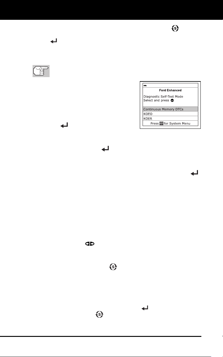
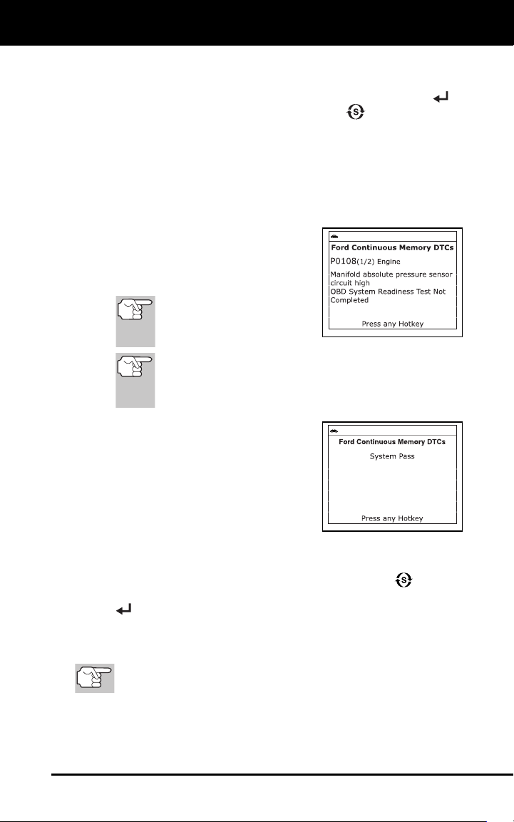
VIEWING OEM ENHANCED DTCs (Ford/Mazda only)
Mazda Enhanced DTCs are available for Mazda-branded
Ford vehicles only.
When Ford OEM Enhanced is chosen from
the System Menu, the Ford OEM Enhanced
menu displays. You may view DTCs for
either the “Continuous Memory Test”,
“KOEO (Key On Engine Off) Test” or
“KOER (Key On Engine Running) Test.”
1. Select the desired option, then press
ENTER
.
If KOER is selected, an advisory message shows.
-
Start and warm the engine to normal operatin
g temperature,
then press EN
TER
. Proceed to step 3.
2. If KOEO or Continuous Memory is selected, an “instructional”
message shows.
Turn the ignition OFF, then back ON. Press ENTER .
Proceed to step 3
.
3. A “O
ne moment please” message displays while the test is in progress.
If the Scan Tool fails to link to the vehicle’s computer, a
“Co
mmunication Error” message shows.
- Ensure your vehicle is OBD2 compliant.
- Verify the connection at the DLC, and verify the ignition is ON
.
-
Turn the ignition OFF, wait 5 seconds, then back ON to reset
the computer.
- Press LINK
to continue.
If the Scan Tool cannot link to the vehicle’s computer after three
attempts, the message “Contac
t Technical Support” displa
ys.
- Pr
ess SYSTEM MENU
to return to the System Menu.
- Turn the ignition off, and disconnect the Scan Tool
.
-
Contact Technical Support for assistanc
e.
If the KOER test was selected, and the vehicle’s engine is not
running, an advisory message s
hows.
-
Start the engine and press ENTER
to try again, or, press
SYSTEM MENU
to return to the System Menu.
Using the Scan Tool
VIEWING ABS DTCs
13
If the KOEO test was selected, and the vehicle’s engine is
runnin
g, an advisory message s
hows.
-
Turn the ignition OFF then back ON and press ENTER
to
try again, or, press SYSTEM MENU
to return to the
System Menu.
4. If the KOER test was selected, an “instructional” message show
s.
Turn the steering wheel to the left, then release.
Press and release the brake pedal.
Cycle the overdrive switch (if equipped).
A “One moment please” message
displays while the test is in progress.
5. Refer to DISPLAY FUNCTIONS
on
page 3 for a descriptio
n of LCD display
elemen
ts.
I
/M MONITOR STATUS
icons are not displayed
when viewing enhanced
DTCs.
In the case of long code definitions, a small arrow is
shown in the upper/ lower right-hand corner of the
code display area to indicate the presence of additional
information.
If no codes are present, a “System
Pa
ss” displays. Press any Hotkey.
6. If more than one code was retrieved
press DTC/FF to display additio
nal
codes one at a time.
7. When the last retrieved DTC h
as been
displayed and DTC/FF is pressed, the
Scan Tool
returns to the “Priority” code.
To view additional enhanced DTCs, repeat steps 1 through 6,
above.
To exit the enhanced mode, press SYSTEM MENU to return
to the System Menu. Select Global OBD, then press ENTER
to return to the Global OBD2 mode.
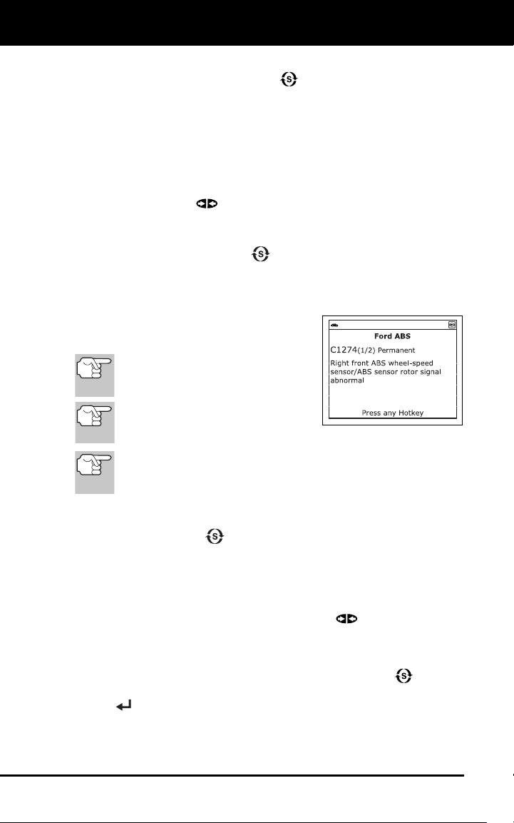
VIEWING ABS DTCs
Refer to the manufacturer’s website for vehicle makes covered.
Reading ABS DTCs
1. When ABS is chosen from the System Menu, a "One moment
pleas
e" message displays while the Scan Tool retrieves the se
lected
DT
Cs.
Using the Scan Tool
VIEWING ABS DTCs
14
If ABS functionality is not supported, an advisory message
shows. Press SYS
TEM MENU
to return to the System Menu.
If the Scan Tool fails to link to the vehicle’s computer, a
"Communication Error" message shows.
- Ensure your vehicle is OBD2 compliant.
- Verify the connection at the DLC, and verify the ignition is ON.
- Turn the ignition OFF, wait 5 seconds, then turn back ON to reset
the computer.
- Press LINK
to continue.
If the Scan Tool cannot link to the vehicle’s computer after three
attempts, the message “Contac
t Technical Support” displays.
- Press SYSTEM MENU
to return to the System Menu.
- Turn the ignition off, and disconnect the Scan Tool.
- Contact Technical Support for assistance.
2. Refer to DISPLAY FUNCTIONS
on
page 3 for a descriptio
n of LCD display
elemen
ts.
If the definition
for the currently
displayed code is not available, an
advisory message shows.
I/M MONITOR STATUS icons are
not displayed when viewing ABS
DTCs.
In the case of long code definitions, a small arrow is shown in
the upper/lower right-hand corner of the code display area to
indicate the presence of additional information.
If no codes are present, the message "No ABS DTC’s are
presently store
d in the vehicle’s computer" shows. Press
SYSTEM MENU
to return to the System Menu.
3. If more than one code was retrieved press DTC/FF, as neces
sary,
to displa
y additional codes one
at a time.
Whenever the Scroll function is used, the Scan Tool’s
communication link with the vehicle’s comp
uter disconnects. To
re-establish co
mmunication, press LINK
again.
4. When the last retrieved DTC has been displayed and DTC/FF
is
p
ressed, the scan tool returns to the “Priority” code.
To exit the enhanced mode, press SYSTEM MENU to return
to the System Menu. Select Global OBD, then press ENTER
to return to the Global OBD2 mode.
Using the Scan Tool
ERASING DIAGNOSTIC TROUBLE CODES (DTCs)
15
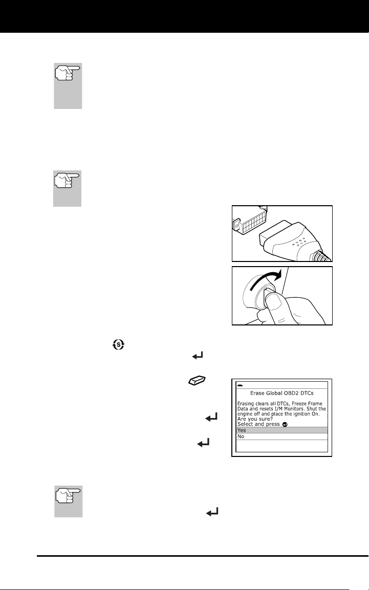
ERASING DIAGNOSTIC TROUBLE CODES (DTCs)
When the Scan Tool’s ERASE function is used to erase
DTCs from the vehicle's on-board computer, "Freeze
Frame" data and manufacturer-specific enhanced data are
also erased. "Permanent" DTCs ARE NOT erased by the
ERASE function.
If you plan to take the vehicle to a Service Center for repair, DO NOT
erase the codes from the vehicle's computer. If the codes are erased,
valuable information that might help the technician troubleshoot the
problem will also be erased.
Erase DTCs from the computer's memory as follows:
When DTCs are erased, the I/M Readiness Monitor Status
program resets status of all Monitors to a not run condition. To
set all Monitors to a DONE status, an OBD2 Drive Cycle must
be performed.
1. If not connected already, con
nect the
Scan Too
l to the vehicle's DLC, and
turn the ignition "On.” (If the Scan Tool
is already connected and linked to
the
vehic
le's computer, proceed directly to
step 3. If not, co
ntinue to step 2.)
2. Perform the Code Retriev
al pr
ocedure
as describ
ed on
page 6.
To erase OBD2 DTCs: Wait until
the codes are displayed,
then
proceed to step 3.
To erase OEM enhanced or ABS DTCs: Press SYSTEM
MENU
to display the System Menu. Select the desired
option, then press ENTER
. Perform the appropriate Code
Retrieval procedure and then pr
oceed to step 3.
3. Press and release E
RASE
. A
confirmation message show
s.
If you are sure you want to proceed,
select YES, then press ENTER
.
If you do not want to proceed, select
NO, then press ENTER
to
cancel
the erase procedure.
If you chose to erase DTCs, a “One moment please…” message
disp
lays while the erase function is in progres
s.
If th
e vehicle’s engine is running, an advisory message shows.
Turn the engine OFF, then turn the ignition back to ON. DO NOT
start the engine. Press ENTER
to continue.

Using the Scan Tool
ABOUT REPAIRSOLUTIONS 2®
16
If the erase was successful, a
confirmation
message shows. The
Scan Tool automatically relinks to the
vehicle’s computer after 3 second
s.
If th
e erase was not successful and
ECU error code $22 is present, an
advisory message displays. Start
the engine and maintain vehicle
speed at 0. Choose Erase DTCs to
try again.
If the erase was not successful, an advisory message shows
indicating the erase request was sent to the vehicle’s computer
.
The S
can Tool automatically relinks to the vehicle’s comput
er
after 3 seconds.
ABOUT REPAIRSOLUTIONS 2®
RepairSolutions 2® is a web-based service created to assist both Do-It-
Yourself and Professional technicians in quickly and accurately
diagnosing and repairing today’s vehicles. RepairSolutions 2 allows you
to view and save the diagnostic data retrieved from a vehicle’s on-board
computer(s) using your Code Reader. At the core of RepairSolutions 2
is an extensive knowledge database, developed by compiling and
analyzing years worth of “real world” vehicle service data.
RepairSolutions 2 builds on manufacturer-recommended diagnostic and
repair information by providing verified, vehicle-specific fixes supplied by
ASE technicians across the country. RepairSolutions 2 also provides
access to an extensive knowledge database including:
Verified Fixes – Find the most likely fixes reported and verified by
AS
E Technicians for the retrieved DT
Cs.
Repair Instructions – View available repair instructions to properly
perform the fix.
Video Tutorials – Watch repair video tutorials for valuable repair
ti
ps.
Technical Service Bulletins – Research known problems reported
by vehicle manuf
acturers.
Safety Recalls – Research known safety concerns applicable to a
vehicl
e.
And much more
. Please visit www.innova.com for additional information.
Hardware Requirements:
Innova Scan Tool with Bluetooth/WiFi
Android or iOS Smart Device
Acce
ssing RepairSolutions 2®
1. Download and install the RepairSolutions 2® app from the App
Store (for iOS devices) or Google Play (for Android dev
ices).
2. Launch the Rep
airSolutions 2 app and log
in to your account.

Using the Scan Tool
CONNECTING TO BLUETOOTH / WIFI
17
If you have not yet established an account, you must register for
a FREE RepairSolutions 2 account before proceeding.
3. Connect the Code Reader to a vehicle and establish a Bluetooth or
WiFi connection with your Smart Device (refer to CONNECTING TO
BLUETOOTH / WIFI, below). Be sure your Smart Device is
connected to an available WiFi network.
The RepairSolutions 2 app will store two WiFi configurations
only.
4. Retrieve diagnostic data (refer to CODE RETRIEVAL PROCEDURE
on page 6 for details).
5. The RepairSolutions 2 app automatically displays a report based on
the retrieved diagnostic data.
If the Code Reader is not connected to WiFi or Bluetooth,
vehicle data will not be saved.
CONNECTING TO BLUETOOTH / WIFI
Launch the RepairSolutions 2 app an follow the prompts to
establish Bluetooth and (optionally) WiFi connections, as follows:
1.
Launch the RepairSolutions 2 app. Select Wifi
Tools Settings
from the menu. Power on your Code Reader, then select from the
list of available devices.
2. When Bluetooth pairing is complete, a confirmation screen displays.
Click Continue.
If a Bluetooth connection cannot be established, an advisory
message displays. Tap Try Again to repeat the pairing process.
3. Follow the on-screen prompts to connect to an available WiFi
network.
You can automatically connect to the network your Smart Device
is currently connected to, or you can manually connect to
another available network.
Note that only 2.4GHz networks are supported.
If you do not wish to connect to a WiFi network at this time, tap
SKIP.
4.
When WiFi pairing is complete, a confirmation screen displays. Click
Continue
to view the “Setup Complete” message, then click
Continue to enter RepairSolutions 2.
If a WiFi connection cannot be established, an advisory
message displays. Tap Try Again to repeat the pairing process.
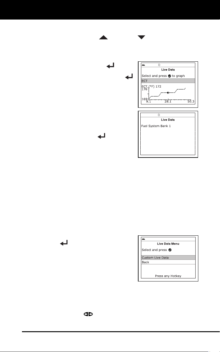
Live Data Mode
VIEWING LIVE DATA
18
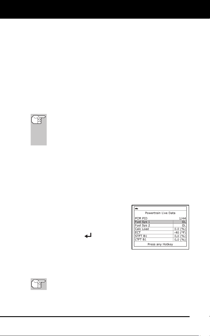
The Scan Tool lets you view and/or record "real-time" Live Data. This
information includes values (volts, rpm, temperature, speed etc.) and
system status information (open loop, closed loop, fuel system status,
etc.) generated by the various vehicle sensors, switches and actuators.
These are the same signal values generated by the sensors, actuators,
switches and/or vehicle system status information used by the vehicle's
computer when calculating and conducting system adjustments and
corrections.
The real time (Live Data) vehicle operating information (values/status)
that the computer supplies to the Scan Tool for each sensor, actuator,
switch, etc. is called Parameter Identification (PID) Data.
Each PID (sensor, actuator switch, status, etc.) has a set of operating
characteristics and features (parameters) that serve to identify it. The
Scan Tool displays this information for each sensor, actuator, switch or
status that is supported by the vehicle under test.
WARNING: If the vehicle must be driven in order to perform a
troubleshooting procedure, ALWAYS have a second person
help you. One person should drive the vehicle while the other
person observes the Scan Tool data. Trying to drive and
operate the Scan Tool at the same time is dangerous, and
could cause a serious traffic accident.
VIEWING LIVE DATA
1. While linked to the vehicle, start the engine, then press LD.
2. A “One moment
please . . .” message displays while the Scan Tool
establishes communication with the vehicl
e.
If the Scan Tool fails to establish communication with the vehicle,
a “C
ommunication Error” message displa
ys.
-
Ensure the vehicle is OBD2 co
mpliant.
-
Verify the connection at the
DLC,
and verify the ignition is ON.
- Turn the ignition OFF, wait 5
seconds, then back ON to reset
the computer.
- Press ENTER
to continue.
3. Real-time Live Data (PID) informati
on
supported by the vehicle under test
displays.
If Live Data is not supported by the vehicle under test, an
advis
ory message displays. Press M to return to the Main Menu
.
Live
Data is not available for your vehicl
e.
Th
e values for the various PIDS displayed may change as the
vehicle's operating conditions change.
Live Data Mode
CUSTOMIZING LIVE DATA (PIDs)
19
4. Only a limited amount of PID data can be displayed on the screen at
one time. If additional PID data is available, a small arrow is shown
on the display. Press UP
and DOWN , as necessary, to view
all av
ailabl
e PID data.
If communication with the vehicle is lost while viewing Live Data,
an advis
ory message displays.
5. Press and release ENTER
to view
the currently s
elected PID in
“graph”
mode. Press a
nd release ENTER
again to return to the PID list.
You can display a maximum of two
PIDs
in "graph" mode at any given
ti
me.
With two PID shown in "graph"
mode, press
and hold LD
to
superim
pose one graph on the
other.
Re
lease LD
to separate the graphs.
6. Pr
ess and hold ENTER
to view the
“e
xpanded” definition for the curren
tly
se
lected PID. Release to return to the PI
D
li
st.
7. If you experience vehicle problems, view and/or compare the
Live
Data (PID) infor
mation displayed on the Scan Tool to specific
ations
in the vehicle's r
epair manu
al.
CUSTOMIZING LIVE DATA (PIDs)
You can customize the Live Data display by placing the Scan Tool in
"Custom Live Data" mode and selecting only the PIDs that you wish to
display.
1. With the Scan Tool in Live Data mode (see VIEWING LIVE DA
TA
on page 18), press and hold LD to access the Live Data Menu, then
releas
e.
2. Select Cust
om Live Data, th
en press
EN
TER
.
If the Scan Tool fails to establish
communication
with the vehicle, a
“Communi
cation Error” message
displays.
-
Ensure your vehicle is OB
D2
com
pliant.
- Verify the connection at the DLC, and verify the ignition is ON.
- Turn the ignition OFF, wait 5 seconds, then back ON to reset
the computer.
- Press LINK
to continue.
Live Data Mode
CUSTOMIZING LIVE DATA (PIDs)
20
If Live Data is not supported by the vehicle under test, an
advis
ory message displays. Press SYSTEM MENU
to return
to the System Menu.
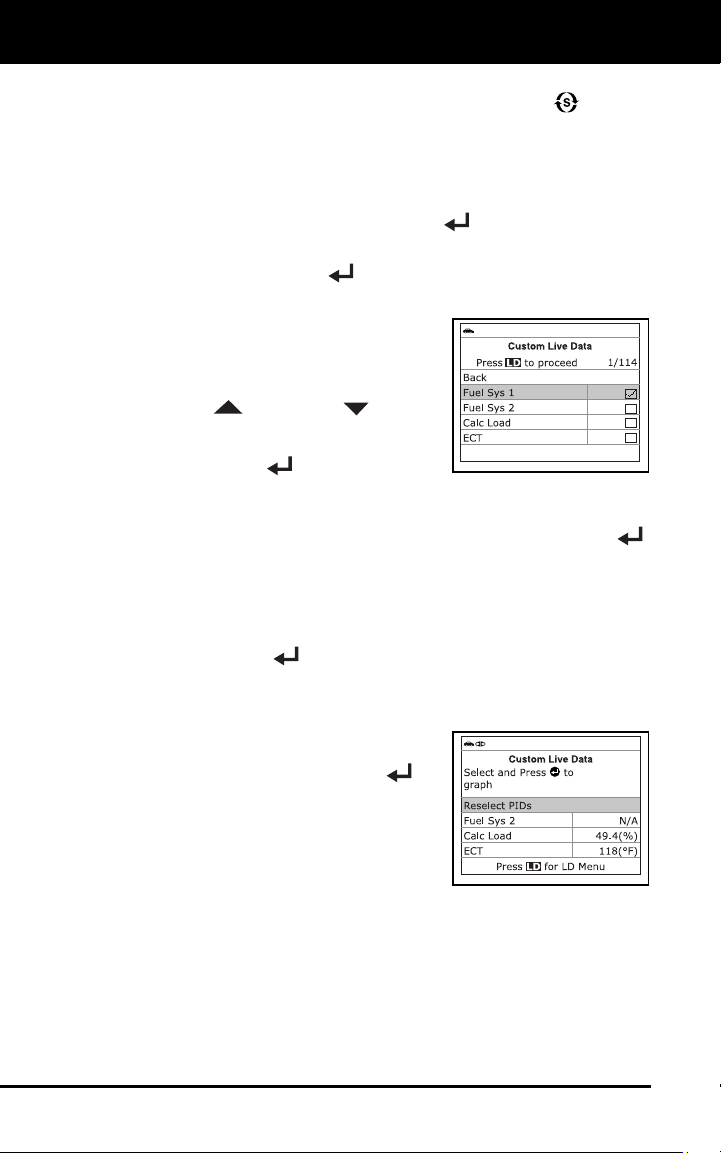
If custom Live Data was previously configured, the Select PIDs
to Use screen d
isplays
.
-
To use the existing custom Live Data selections, select Us
e
existing PIDs, then press EN
TER
. Proceed to step 5.
- To configure new custom Live Data, select Select new PIDs,
then press ENTER . The Custom Live Data menu displays.
Proceed to step 3.
If custom Live Data was not
previo
usly se
lected, the Custom
Live Data men
u displays. Proc
eed
to step 3.
3. Press UP
and DOWN to scroll
through the av
ailable PIDs.
When the
PID you wish t
o display is high
lighted,
press EN
TER
(a "checkmark"
shows to confir
m your selection). Repeat until only the PIDs you
want to display
are selected.
To deselect a PID, highlight the PID, then press ENTER .
The chec
kmark is removed.
4. When yo
u are finished making your selection(s), press LD
to
continu
e
.
If no PIDs have been selected, an advisory message displays.
Press EN
TER
to return to the Custom Live Data menu.
5. The Scan To
ol is now in "Custo
m Live Data" mode. Only the PIDs
you selected are shown.
To change the current custom Live
Data selections, select Rese
lect
PI
Ds, then press ENTER
to
return to
the Custom Live
Data
menu. Repe
at step 3
.
6. To ex
it the "Custom Live Data
" mode,
press LD to r
eturn to the Live Da
ta
Menu.
Additional Functions
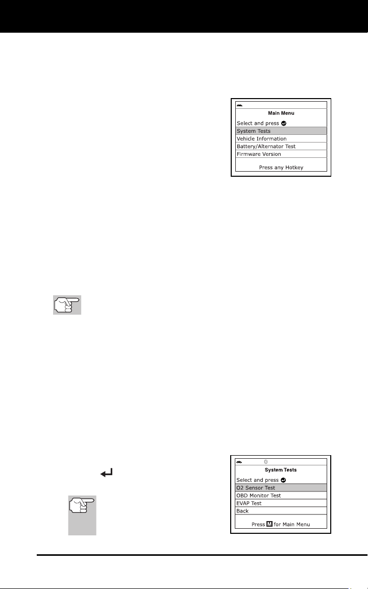
SYSTEM TEST MENU
21
In addition to retrieving Diagnostic Trouble Codes (DTCs), you can use
the scan tool to perform additional diagnostic tests, to view diagnostic
and vehicle information stored in your vehicle's on-board computer, and
to configure the scan tool for your particular needs. Additional tests and
related functions are accessed through the Main Menu. The following
functions are available:
System Tests – Displays the System
Test menu, wh
ich lets your retrieve an
d
vie
w results for the O2 Sensor
Test and
OBD Mon
itor Test, and lets you init
iate
a test of
the vehicle’s EVAP syst
em.
Vehicle Information – Displays the
Vehicle Info menu, which lets you
retrieve and view reference information
for the vehicle u
nder test.
Battery/Alternator Monitor – Performs a check of the vehicle’s
battery and alternator system to ensure the system is operating
with
in acceptable lim
its.
Firmware Version – Displays the diagnostic tool’s firmware version.
Tool Library – Displays the Tool Library menu, which provides
access to OBD1 and OBD2 DTC libraries and to definitions
for
Monitor ico
ns and LED indi
cations.
Tool Settings – Displays the Tool Settings menu, which lets you
make several a
djustments and settings to configure the diagnostic
tool to your particular nee
ds.
The Vehicle Information op
tion is shown only when the scan
tool is in Global OBD2 mode.
SYSTEM TEST MENU
Additional tests are accessed through the System Tests menu. The
following functions are available:
O2 Sensor Test - Retrieves and displays O2 sensor monitor test
results from your vehicle's on-board computer.
OBD Monitor Test - Retrieves and displays test results for
emiss
ion-related powertrain components and
systems that are not
continu
ously mo
nitored.
EVAP Test - Performs a leak test for the vehicle's EVAP system.
1. While linked to the vehic
le, press M
.
The Main Menu displays.
2. Select Syste
m Tests, th
en press
EN
TER
.
The System Test menu displays.
If
System Tests is not shown
on the Main Menu, the System
Tests functions are not
available for your vehicle.
Additional Functions
SYSTEM TEST MENU
22
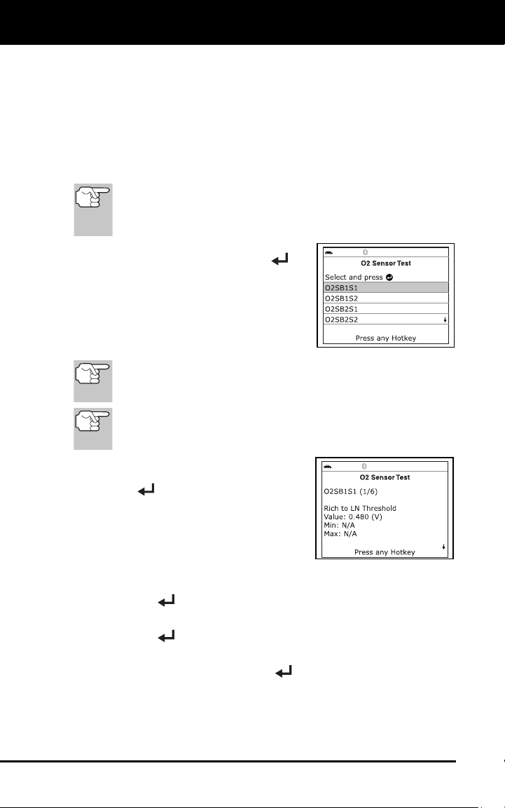
O2 Sensor Test
OBD2 regulations require that applicable vehicles monitor and test operation
of the oxygen (O2) sensors to identify problems that can affect fuel
efficiency and vehicle emissions. These tests are performed automatically
when engine operating conditions are within predefined limits. Results of
these tests are stored in the on-board computer's memory.
The O2 Sensor Test function lets you retrieve and view O2 sensor
monitor test results for the most recently completed tests from your
vehicle's on-board computer.
The scan tool does not perform O2 sensor tests, but retrieves
results from the most recently performed O2 sensor tests from
the on-board computer's memory. You may retrieve O2 sensor
test results for only one test of one sensor at any given time.
1. From the System Test menu, select
O2
Sens
or Test, then press ENTER
.
2. A "One moment please..." message
displays, follo
wed by the select sensor
screen.
The Select Sensor screen displays.
The scree
n shows all O2 sensors
applicable to the vehicle under te
st.
If O2 sensor te
st data is not presently stored in the vehicle’s
computer, an advisory message displays. Press M to return to
the Main Menu.
If O2 sensor tests are not supported by the vehicle under test,
an advisory message displays. Press M to return to the Main
Menu.
3. Select the O2 sensor for which yo
u
wis
h to view test results, then
press
EN
TER
to display the test results.
4. When test resu
lts have bee
n retrieved,
data for the selected
sensor
test will
show on the d
iagnostic tool
's display.
5. Wh
en you have finished viewing th
e
retr
ieved test data:
To view test results for the next sensor, select Next, then press
ENTER
.
To return to the Select Sensor screen, select Back, then press
EN
TER
.
6. When y
ou have finished viewing test data for all desired sens
ors,
select Ba
ck, then press ENTER
to return to the System Test
menu; or, press M
to return to th
e Main Menu.
Additional Functions
SYSTEM TEST MENU
23
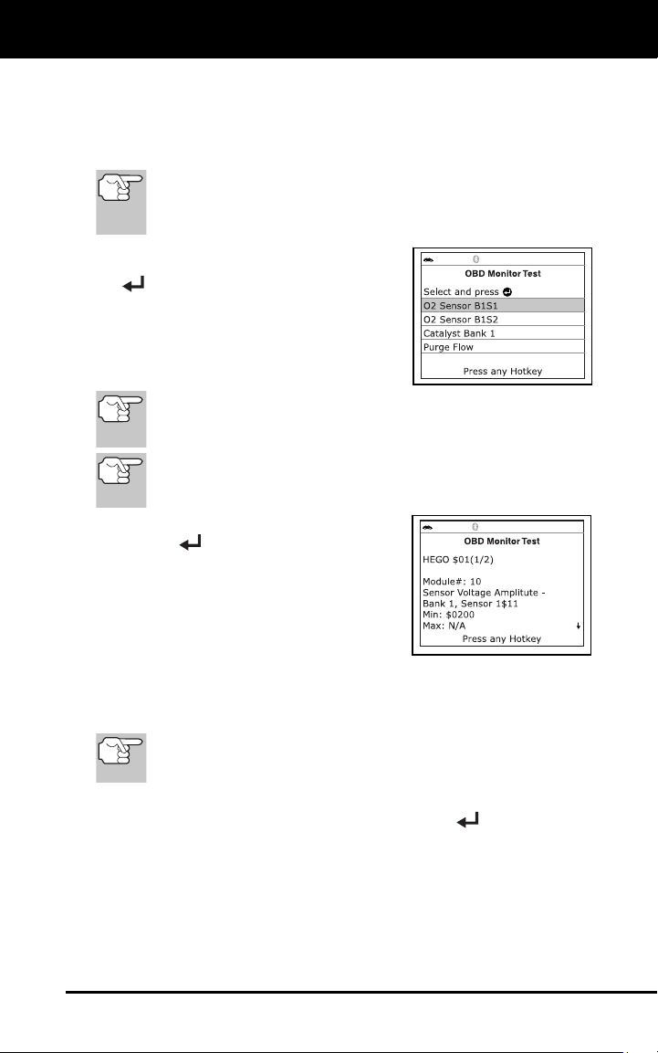
OBD Monitor Test
The OBD Monitor Test function retrieves and displays test results for
emission-related powertrain components and systems that are not
continuously monitored. The tests available are determined by the
vehicle manufacturer.
The diagnostic tool does not perform the OBD monitor test, but
retrieves results from the most recently performed tests from
the on-board computer’s memory. You may retrieve OBD
monitor test results for only one test at any given time.
1. From the System Test menu
, select
OB
D Monitor Test, then press ENTER
.
2. A “One moment please. . .” message
displays, followed by the Se
lect Test
screen. (Refer
to the vehicle’s service
repair manual for information related to
non-continuous tests.)
If OBD monitor test data is not presently stored
in the vehicle’s
computer, an advisory message displays. Press M to return to
the Main Menu.
If OBD monitor tests are not supported by the vehicle under test,
an advisory message displays. Press M to return to the Main
Menu.
3. Select the desired test,
then press
EN
TER
to display the test results.
The display shows the following
informati
on:
Test ID number
Module ID number
Component ID number
Min or Max test limit (Only one test limit, either Min or Max, is
shown for any given test.)
Test Value and status
Status is calculated by the diagnostic tool by comparing the
Test Value against the displayed test limit (either Min or Max).
Status is shown as either Low, High or OK.
4. When you have finished viewing the retrieved test data, select Back
on the Select Test screen, then press ENTER
to return to the
System Tes
t menu; or, press M to return to the Main Menu
.
EVAP Test
The EVAP Test function lets you initiate a leak test for the vehicle's
EVAP system.
Additional Functions
VIEWING VEHICLE INFORMATION
24
The scan tool does not perform the leak test, but signals to
vehicle's on-board computer to initiate the test. The vehicle
manufacturer determines the criteria and method for stopping
the test once it has been started. Refer to the vehicle's service
repair manual to determine the procedures necessary to stop
the test.
1. From the System Test menu, select EVAP Test, then press ENTER
.
2. A "One moment please..."
message
displays.
3. When the E
VAP leak test has been
initiated by the vehicle's on-board
computer, a confirmation message
displays. Select Back
, then press
EN
TER
to return to the System Test
menu; or, press M to return to the Main
Menu.
S
ome vehicle manufacturers do not allow diagnostic tools or other
external devices to control vehicle systems. If the EVAP Test is
not supported by the vehicle under test, an advisory message
shows on the diagnostic tool's display. Press the M button to
return to the Main Menu.
VIEWING VEHICLE INFORMATION
The Scan Tool offers three options for
retrieving reference information for the
vehicle under test; Vehicle ID, Available
Modules and IPT (In-use Performance
Tracking).
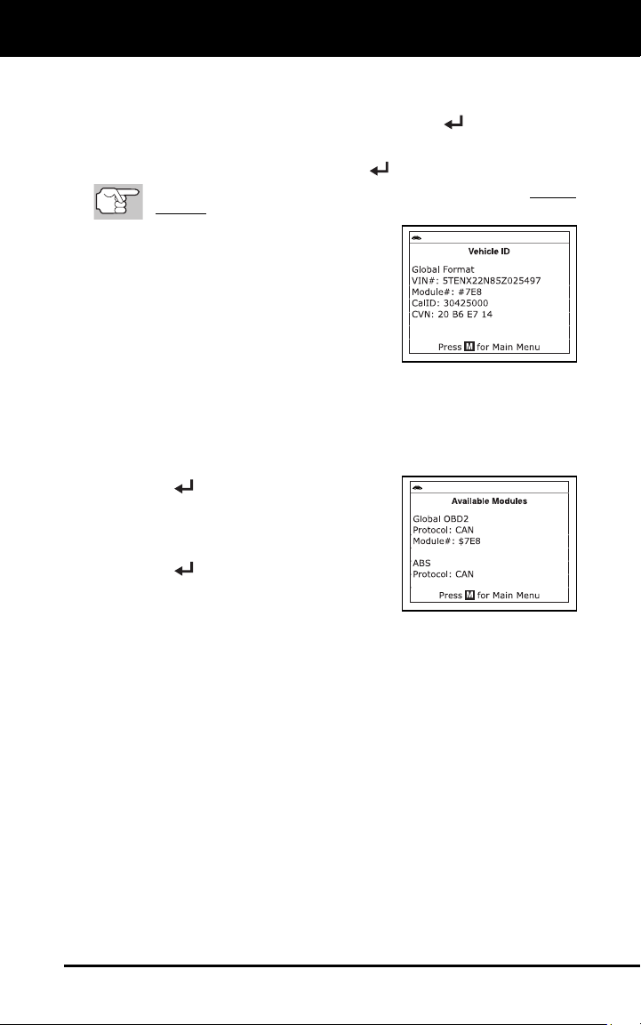
Retrieving Vehicle ID Information
The Vehicle ID function is applicable to model year 2000 and
newer OBD2-compliant vehicles.
The Scan Tool can retrieve a list of information (provided by the vehicle
manufacturer), unique to the vehicle under test, from the vehicle's on-
board computer. This information may include:
The vehicle's VIN number
The control module identification number
The vehicle's calibration ID(s). These IDs uniquely identify the
software version(s) for the vehicle's contro
l module(s).
The Vehicle's Calibration Verification Number(s) (CVNs) required by
ODB2 regulations. CVNs are used to determine if emission-related
calibrations for the vehicle und
er test have been changed. One or
more CV
Ns may be returned by the vehicle's co
mputer.
Additional Functions
VIEWING VEHICLE INFORMATION
25
1. While linked to a vehicle, press M.
The “Main Menu” displays.
2. Select Vehicle Information, then press EN
TER
.
The Vehicle Information menu displays.
3. Select Vehicle ID, then press ENTER
.
T
he first time the Vehicle ID function is used, it may take several
minutes to retrieve the information from the vehicle's computer.
4. When the retrieval process is
completed, the vehicle ID information
disp
lays.
5. When
you have finished viewing the
retrieved vehicle ID information, press M
to exit
.
Viewing Available Modules
The Scan Tool can retrieve a list of modules supported by the vehicle
under test.
1. While linked to a vehicle, press M
.
The “Main Menu” displays.
2. Select Vehic
le Information, then press
ENTER
.
The Vehicle Information menu dis-
plays.
3. Select Available Modules
, then press
EN
TER
.
4. When the retrieval process
is completed,
a complete list of modules sup
ported by
the vehic
le under test displays.
5. When you have finished viewing the list of available modules,
press
M
to exit.
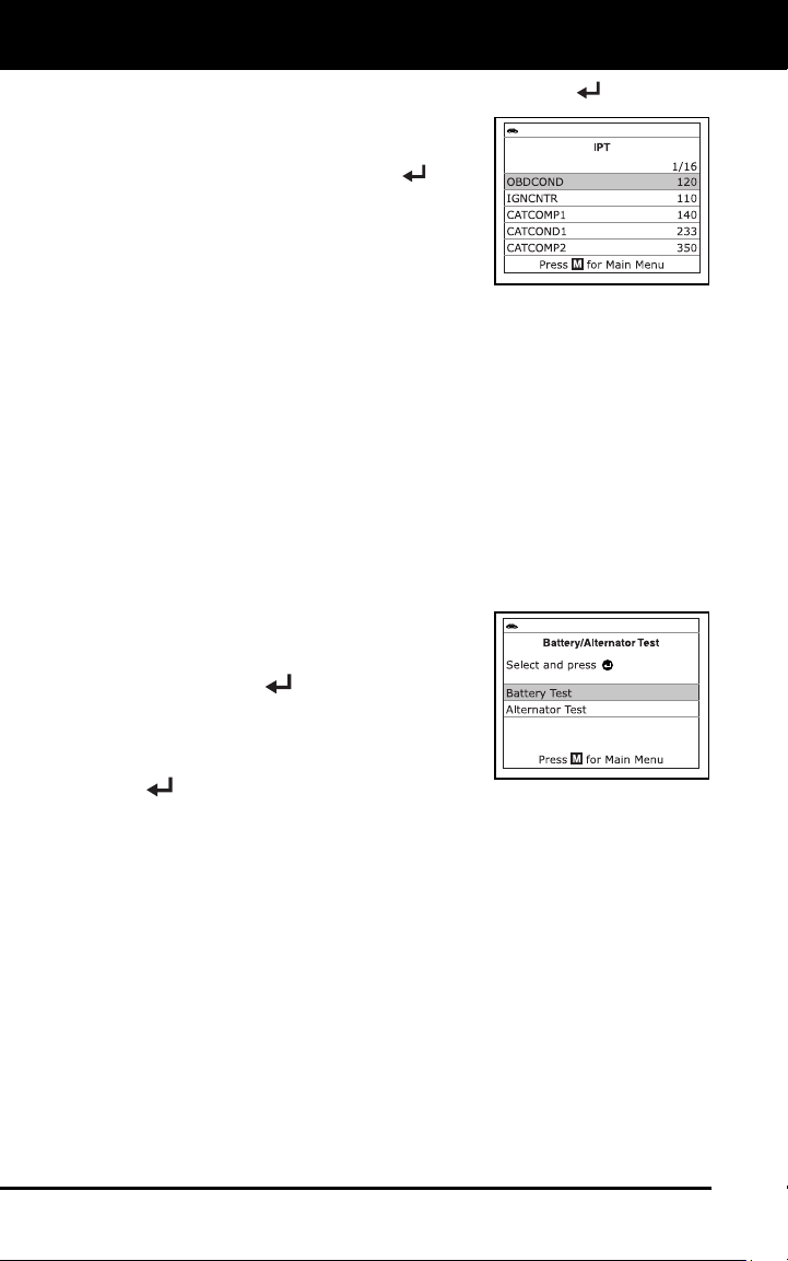
Viewing In-use Performance Tracking (IPT)
The Scan Tool can retrieve In-use Performance Tracking (IPT) statistics
for monitors supported by the vehicle under test. Two values are
returned for each monitor; the number of times that all conditions
necessary for a specific monitor to detect a malfunction have been
encountered (XXXCOND), and the number of times that the vehicle has
been operated under the specific conditions for the monitor (XXXCOMP).
Statistics are also provided for the number of times the vehicle has been
operated in OBD monitoring conditions (OBDCOND), and the number of
times the vehicle’s engine has been started (IGNCNTR).
1. While linked to a vehicle, press M
.
The “Main Menu” displays.
Additional Functions
BATTERY/ALTERNATOR TEST
26
2. Select Vehicle Information, then press the ENTER
button.
The Vehicle Information menu
displays.
3. Select IPT, then press ENTER
.
4. When
the retrieval process is completed,
the In-use Performance Tracking
statistics for the vehicle under test
display.
If In-use Performance Tracking is not available for your vehicle,
an adv
isory message shows on the diagnostic tool’s displa
y.
Press M to return to the Main Menu.
5. When you ha
ve finished viewing the statistics, press M to exit.
BATTERY/ALTERNATOR TEST
The Scan Tool can perform a check of the vehicle’s battery and
alternator system to ensure the system is operating within acceptable
limits. You can perform a battery check only, or an alternator system
(battery and alternator) check.
To perform a battery check ONLY:
1. Press M
and release.
The Main Menu displays.
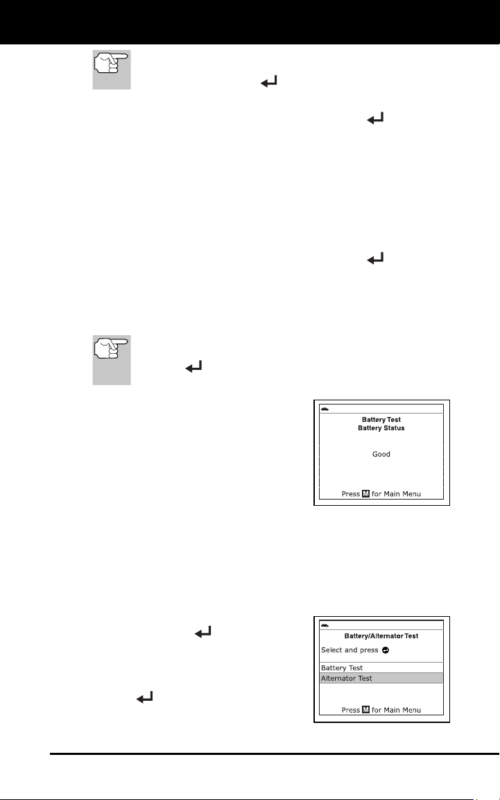
2. Select Battery/Alternator Test
, then
press EN
TER
.
The Battery/Alternator Monitor
Menu displays
.
3. Select B
attery Test, then press ENTER
.
An “instructional” message displays, showing the procedures to
prepare the vehicle for the batte
ry check.
4. Prepare the veh
icle for the batte
ry check:
Turn the engine off.
Place the transmission in PARK or NEUTRAL, and set the
parkin
g
brake.
Make a visual check of the battery’s condition. If the battery
terminals are c
orroded or other damage is present, clean
or
replac
e the battery as appropria
te.
For “unsealed” batteries, make sure the water level in each cell
is above the battery plates.
Turn the ignition on. DO NOT start the engine.
5. Press EN
TER to
begin the battery check.
Additional Functions
BATTERY/ALTERNATOR TEST
27
If the engine is running, an advisory message shows. Turn
the engine off, then turn the ignition on. DO NOT start the
engine. Press ENTER
to continue.
An “instructional” message shows.
6. Turn the vehic
le’s headlights on, then press ENTE
R
to continue.
A “countdown” message shows while the battery check is in
process.
If battery voltage is less than 12.1 volts, an advisory message
shows. Press M to return to the Main Menu. Turn the ignition o
ff
and discon
nect the scan tool from the vehicle. Fully charge the
battery, then re
peat the battery check.
If battery voltage is greater than 12.1 volts, an “instructional”
message sh
ows.
7. Turn the vehicle’s headlights off, then press ENTE
R
to continue.
An “instructional” message shows.
8. Start the vehicle’s engin
e. Allow the engine to
run for several
seconds, then
turn the engine
off. Repeat for a total of three
“start/stop” cycles.
If
the If the scan tool did not detect “cranking status” for the
vehicle’s engine, an advisory message shows. Press
ENTER
to repeat the battery check, or, press M to
return to the Main Menu.
9. When the battery check is co
mplete, a
results screen
displays the battery
status. The System Status LEDs
provide a PASS/FAIL indication, as
follows:
Green = Good
Yellow = Normal
Red = Warning/Bad
10. Press M to return to the Main Menu.
To perform a
n alternator system check:
1. Press M
and release.
The Main Menu displays.
2. Select Battery/Alternator Monitor
,
then press EN
TER
.
The Battery/Alternator Test Menu
displays.
3. Select Al
ternator Monitor, then press
ENTER
.
An “instructional” message shows.
Additional Functions
VIEWING THE FIRMWARE VERSION - THE TOOL LIBRARY
28
4. Start and warm the engine to normal operating temperature. Turn on
the headlights. Press ENTER
to continue.
An “instructional” message shows.
5. Press the accelerator pedal to raise engin
e speed to 2000 RPM,
and maintain the engine speed.
When engine speed is within the required range, the alternator
test begins. A p
rogress screen
shows.
When the “countdown” timer expires, an “instructional” message
shows.
6. T
urn the vehicle’s headlights off, and
return the engine to idle spee
d.
A “One moment please…” message
displays while the test results are
retrieved.
7. When the alternator check is
complete,
a results screen shows charging
system
voltage and in
dicates whether or not
the
charging syste
m is within ac
ceptable
lim
its. The SYSTEM STATUS LEDs
provide a PASS/FAIL indication,
as
f
ollows:
Green = System within limits
Yellow = Over charging or under
charging
Red = Excessive over charging or
under charg
i
ng
If the alternator voltage is less than 9 V, the red, yellow and
green SY
STEM STATUS LEDs will flash on and
off.
8. Press M to return to the Main Menu.
VIEWING THE FIRMWARE VERSION
1. Select Firmware Version in the Main
Menu, then press ENTER
.
The Firmware Version screen displays.
The screen shows the scan tool’s
current firmware version, bootloader
version and database version.
2. Press M to return to the Main
Menu.
THE TOOL LIBRARY
The Tool Library contains valuable reference information for the Scan
Tool. The following functions are available:
Additional Functions
THE TOOL LIBRARY
29
Tool Icons – Shows the full names for the I/M MONITOR STATUS
icons and descriptions of informational icons shown on the scan
tool’s display.
DTC Library – Provides access to a library of OBD2 DTC definitions.
LED Definitions – Provides descriptions of the meaning of the scan
tool SY
STEM STATUS LEDs
.
1. While linked to the vehic
le, press M
.
The Main Menu displays.
2. Select To
ol Library, then press
ENTER
..
The Tool Library menu displays.
Viewing To
ol Icon Descriptions
The I/M MONITOR STATUS icons on the scan tool’s LCD display
provide an indication of the “Completed / Not Complete” status for all I/M
Monitors supported by the vehicle under test. The Tool Icons function
displays the full name for each Monitor icon, as well as descriptions of
the meanings of other informational icons shown on the scan tool’s
display.
1. From the Tool Library menu,
select
Tool
Icons, then press ENTER
.
The Tool Icons screen displays.
The screen shows a list of the 15
Monitor icons, along with th
e full
name for each icon, as well as
descript
ions of the meaning
s of
other informational
icons. Us
e the
UP
and DOWN buttons, as necessary, to scroll the list.
2. When you have finished viewing the tool icon descriptions, press M
to return to the
Main Menu.
Using the DTC Library
1. From the Tool Library menu, select DTC Library, then press
ENTER
.
The Select Library screen displays.
2. Select
OBD2 Library, then press
ENTER
.
The Select Manufacturer screen
displays.
3. Select the desired vehic
le manu
facturer,
then press ENTER .
The Enter DTC screen displays. The screen shows the code
“P0001,” with the “P” highlig
hted.
Additional Functions
ADJUSTMENTS AND SETTINGS
30
4. Use the UP and DOWN buttons,
as necessary, to scroll to the desired
DTC type (P=Powertrain, U=Network,
B=Body, C=Chassis), then press the
DTC button.
The selected character displays solid,
and the next character is highlighted.
5. Select the remaining digits in the DTC
in the same way. When you have
selected all the DTC digits, press
ENTER
to continue.
6. When you have finished viewing the DTC
definition, highlight Back, then press
ENTER
to return to the Enter DTC
screen and enter additional DTCs; or,
press M
to return to the Main Menu.
If a definition for the DTC you entered is not available, an advisory
message shows Highlight Back, then press ENTER
to return
to the Enter DTC screen and enter additional DTCs; or, press M
to
return to the Main Menu.
Viewing LED Definitions
The SYSTEM STATUS LEDs on the scan tool provide a visual
indication of the I/M Readiness status of the vehicle under test. The
LED Definitions function provides a description of the meanings of the
green, yellow and red SYSTEM STATUS LEDs.
1. From the Tool Library menu, select LED
Definitions, then press ENTER
.
The LED Meaning screen displays.
The screen provides a description of
the meanings of the green, yellow
and red SYSTEM STATUS LEDs.
2. When you have finished viewing the
LED meanings, press M
to return to the
Main Menu.
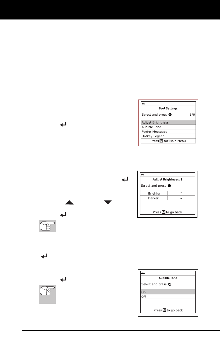
ADJUSTMENTS AND SETTINGS
You can access the Adjustments and Settings MENU while the Scan Tool is
in “Live Data” mode. The Scan Tool lets you make several adjustments and
settings to configure the Scan Tool for your particular needs. The following
adjustments and settings are available:
Adjust Brightness: Adjusts the brightness of the display screen.
Audible Tone: Turns the Scan Tool’s audible tone “on” and “off.”
When turned “on,” a tone sounds each time a button is pressed.
Additional Functions
ADJUSTMENTS AND SETTINGS
31
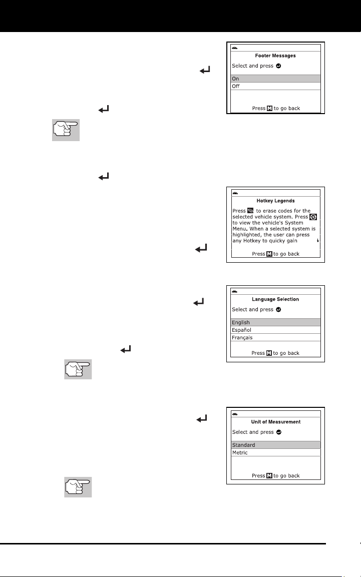
Footer Messages: Turns the navigational “footers” at the bottom of
most display scr
eens “on” and “off.”
Hotkey Legend: Shows functional descriptions for the diagnostic
tool’s hotk
e
ys.
Language Selection: Sets the display language for the Scan Tool
to English, French or Span
ish.
Unit of Measurement: Sets the Unit of Measurement for the Scan
T
ool’s display to USA or Metric.
To enter the Tool Settings Menu:
1. While linked to the vehicle, press and
release the M
button.
The Main Menu displays.
2. Select Tool
Settings
, then press
EN
TER
.
The Tool Settings menu displays.
3. Make adju
stments and settings as
follows.
Adjusting Display Brightness
1. Select Adjust Brightness
in the Tool
Settings men
u, then press ENTER
.
The Adjust Brightness screen
displays.
2. Press UP
and DOWN
to make
the disp
lay lighter or darker, th
en press
ENTER
to save your changes.
To return to the Tool Settings menu without making
changes, press M.
Enabling/Disabling the Audible Tone
1. Select Audible Tone in the Tool Settings menu, then press ENTER
.
The Audible Tone screen displays.
2. Select On or Off as des
ired, then press
ENTER
to save your changes.
To return to the Tool Settings
menu without making changes,
press M.
Additional Functions
ADJUSTMENTS AND SETTINGS
32
Enabling/Disabling Navigational Footers
1. Select Footer Messages
in the Tool
Settings men
u, then press ENTER
.
The Footer Messages screen displays.
2. Select On of Off as desired, th
en press
EN
TER
to save your changes.
To return to the Tool Settings menu without making changes,
press M.
Viewing the Hotkey Legend
1. Select Hotkey Legend in the Tool Setting
s menu, then press
EN
TER
.
The Hotkey Legends screen displays.
The screen shows a functional
descript
ion of each of the
scan
tool’s hotk
e
ys.
2. When you hav
e finished viewing the
Hotkey Legend, press ENTER
to
return to the T
ool Settin
gs menu.
Selecting the
Display Language
1. Select Language Selection in the Tool
Settings menu, then press ENTER
.
The Language Selection screen dis-
plays.
2. Select
the desired display language, then
press ENTER
to save your changes.
To return to the Tool Settings
menu without making changes, press M.
Setting the Unit of Measurement
1. Select Unit of Measurement in the Tool
Settings menu, then press ENTER
.
The Unit of Measurement screen
disp
lays.
2. Select th
e desired unit of measuremen
t,
then
choose Save to save
your changes.
To return to
the Tool Settings
menu without making changes, press M.
Exiting the Tool Settings Menu
Press M to return to the Main Menu.

Warranty and Servicing
33
LIMITED ONE YEAR WARRANTY
The Manufacturer warrants to the original purchaser that this unit is free
of defects in materials and workmanship under normal use and
maintenance for a period of one (1) year from the date of original
purchase.
If the unit fails within the one (1) year period, it will be repaired or
replaced, at the Manufacturer’s option, at no charge, when returned
prepaid to the Service Center with Proof of Purchase. The sales receipt
may be used for this purpose. Installation labor is not covered under this
warranty. All replacement parts, whether new or remanufactured,
assume as their warranty period only the remaining time of this warranty.
This warranty does not apply to damage caused by improper use,
accident, abuse, improper voltage, service, fire, flood, lightning, or other
acts of God, or if the product was altered or repaired by anyone other
than the Manufacturer’s Service Center.
The Manufacturer, under no circumstances shall be liable for any
consequential damages for breach of any written warranty of this unit.
This warranty gives you specific legal rights, and you may also have
rights, which vary from state to state. This manual is copyrighted with all
rights reserved. No portion of this document may be copied or
reproduced by any means without the express written permission of the
Manufacturer. THIS WARRANTY IS NOT TRANSFERABLE. For
service, send via U.P.S. (if possible) prepaid to Manufacturer. Allow 3-4
weeks for service/repair.
SERVICE PROCEDURES
If you have any questions, require technical support or information on
UPDATES and OPTIONAL ACCESSORIES, please contact your local
store, distributor or the Service Center.
USA & Canada:
(800) 544-4124 (6:00 AM-6:00 PM, Monday through Saturday)
All others: (714) 241-6802 (6:00 AM-6:00 PM, Monday through
Saturday)
FAX: (714) 241-3979 (24 hr.)
Web: www.innova.com