
Table of Contents
i
SAFETY PRECAUTIONS
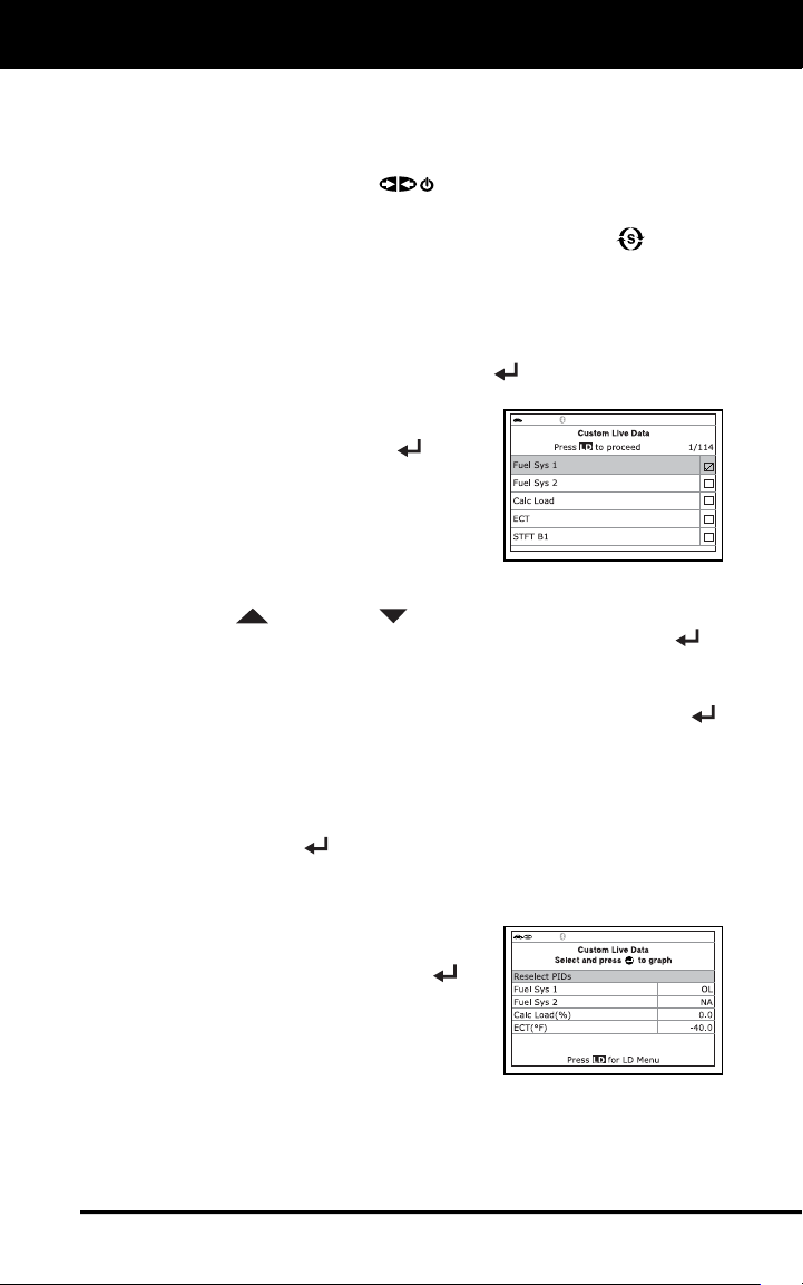
SAFETY FIRST! ....................................................................... 1
SCAN TOOL CONTROLS
CONTROLS AND INDICATORS ............................................. 2
DISPLAY FUNCTIONS ............................................................ 4
BATTERY REPLACEMENT ..................................................... 5
USING THE SCAN TOOL
CODE RETRIEVAL PROCEDURE .......................................... 7
THE SYSTEM MENU ................................................................ 12
VIEWING OEM ENHANCED DTCs (except Ford/Mazda) ....... 12
VIEWING OEM ENHANCED DTCs (Ford/Mazda only) ........... 13
VIEWING ABS DTCs ............................................................... 15
VIEWING SRS DTCs ............................................................... 16
VIEWING TPMS DTCs ............................................................. 18
NETWORK TEST ..................................................................... 19
ERASING DIAGNOSTIC TROUBLE CODES (DTCs) ............. 21
ABOUT REPAIRSOLUTIONS 2® ............................................ 23
CONNECTING TO BLUETOOTH / WIFI ................................. 24
LIVE DATA MODE
VIEWING LIVE DATA .............................................................. 25
CUSTOMIZING LIVE DATA (PIDs) .......................................... 26
RECORDING (CAPTURING) LIVE DATA ................................ 28
LIVE DATA PLAYBACK ........................................................... 31
ADDITIONAL TESTS
SYSTEM CHECKS MENU ....................................................... 33
PERFORMING SERVICE RESETS ......................................... 36
PERFORMING A SERVICE CHECK ....................................... 41
BATTERY/ALTERNATOR TEST ............................................. 42
VIEWING DRIVE CYCLE PROCEDURES .............................. 44
USING THE DLC LOCATOR ................................................... 46
VIEWING VEHICLE INFORMATION ....................................... 46
VIEWING THE FIRMWARE VERSION .................................... 48
THE TOOL LIBRARY ............................................................... 48
ADJUSTMENTS AND SETTINGS ........................................... 51
USING SCAN TOOL MEMORY
VIEWING DATA IN MEMORY ................................................. 54
WARRANTY AND SERVICING
LIMITED ONE YEAR WARRANTY ........................................... 57
SERVICE PROCEDURES ....................................................... 57
Safety Precautions
SAFETY FIRST!
1
SAFETY FIRST!
This manual describes common test procedures used by experienced
service technicians. Many test procedures require precautions to avoid
accidents that can result in personal injury, and/or damage to your
vehicle or test equipment. Always read your vehicle's service manual
and follow its safety precautions before and during any test or service
procedure. ALWAYS observe the following general safety precautions:
When an engine is running, it produces carbon monoxide,
a toxic and poisonous gas. To prevent serious injury or
death from carbon monoxide poisoning, operate the
vehicle ONLY in a well-ventilated area.
To protect your eyes from propelled objects as well as hot
or caustic liquids, always wear approved safety eye
protection.
When an engine is running, many parts (such as the
coolant fan, pulleys, fan belt etc.) turn at high speed. To
avoid serious injury, always be aware of moving parts.
Keep a safe distance from these parts as well as other
potentially moving objects.
Engine parts become very hot when the engine is running.
To prevent severe burns, avoid contact with hot engine
parts.
Before starting an engine for testing or troubleshooting,
make sure the parking brake is engaged. Put the
transmission in park (for automatic transmission) or
neutral (for manual transmission). Block the drive wheels
with suitable blocks.
Connecting or disconnecting test equipment when the
ignition is ON can damage test equipment and the
vehicle's electronic components. Turn the ignition OFF
before connecting the Scan Tool to or disconnecting the
Scan Tool from the vehicle’s Data Link Connector (DLC).
To prevent damage to the on-board computer when taking
vehicle electrical measurements, always use a digital
multimeter with at least 10 megOhms of impedance.
Fuel and battery vapors are highly flammable. To prevent
an explosion, keep all sparks, heated items and open
flames away from the battery and fuel / fuel vapors. DO
NOT SMOKE NEAR THE VEHICLE DURING TESTING.
Don't wear loose clothing or jewelry when working on an
engine. Loose clothing can become caught in the fan,
pulleys, belts, etc. Jewelry is highly conductive, and can
cause a severe burn if it makes contact between a power
source and ground.
N
L
D
R
P
Scan Tool Controls
CONTROLS AND INDICATORS
2
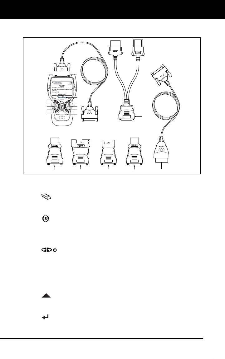
CONTROLS AND INDICATORS
Figure 1. Controls and Indicators
See Figure 1 for the locations of items 1 through 20, below.
1.
ERASE button - Erases Diagnostic Trouble Codes (DTCs),
and “Freeze Frame” data from your vehicle’s computer, and resets
Monitor status.
2.
SYSTEM MENU button – When pressed, displays the System
Test Menu.
3. DTC/FF button - Displays the DTC View screen and/or scrolls the
LCD display to view DTCs and Freeze Frame data.
4.
POWER/LINK button - When not connected to a vehicle,
turns the Scan Tool “On” and “Off”. When connected to a vehicle,
links the Scan Tool to the vehicle’s PCM.
5. M button – When pressed, displays the Main Menu.
6. LD button – When pressed while linked to a vehicle, places the
Scan Tool in Live Data mode.
7.
UP button – When in MENU mode, scrolls UP through the
menu options. When LINKED to a vehicle, scrolls UP through the
current display screen to display any additional data.
8.
ENTER button - When in MENU mode, confirms the selected
option or value.
20
19
14
1
3
2
4
6
5
7
11
12
13
8
9
15 18
16 17
10

Scan Tool Controls
CONTROLS AND INDICATORS
3
9. DOWN button - When in MENU mode, scrolls DOWN through
the menu options. When LINKED to a vehicle, scrolls DOWN
through the current display screen to display any additional data.
10. GREEN LED - Indicates that all engine systems are running
normally (all Monitors on the vehicle are active and performing their
diagnostic testing, and no DTCs are present).
11. YELLOW LED - Indicates there is a possible problem. A “Pending”
DTC is present and/or some of the vehicle’s emission monitors have
not run their diagnostic testing.
12. RED LED - Indicates there is a problem in one or more of the
vehicle’s systems. The red LED is also used to show that DTC(s)
are present. DTCs are shown on the Scan Tool’s display. In this
case, the Malfunction Indicator (“Check Engine”) lamp on the
vehicle’s instrument panel will light steady on.
13. Display - Color LCD display shows menu and submenus, test
results, Scan Tool functions and Monitor status information. See
DISPLAY FUNCTIONS, following, for more details.
14. CABLE - Connects the Scan Tool to the vehicle’s Data Link
Connector (DLC).
Items 15 through 20 are available with purchase of the
optional OBD1 Adaptor Kit and OBD1 firmware upgrade.
15. CHRYSLER Connector Cable Adaptor - Installs on cable (item 14)
when connecting to a Chrysler OBD1 Data Link Connector.
16. FORD Connector Cable Adaptor - Installs on cable (item 14) when
connecting to a Ford OBD1 Data Link Connector.
17. GM Connector Cable Adaptor - Installs on cable (item 14) when
connecting to a GM OBD1 Data Link Connector.
18. HONDA Connector Cable Adaptor - Installs on cable (item 14)
when connecting to a Honda OBD1 Data Link Connector.
19. OBD II Cable - Connects the scan tool to the vehicle's Data Link
Connector (DLC) when retrieving codes from OBD II systems.
20. TOYOTA Connector Cable Adaptor - Installs on cable (item 14)
when connecting to a Toyota OBD1 Data Link Connector.
Scan Tool Controls
DISPLAY FUNCTIONS
4
DISPLAY FUNCTIONS
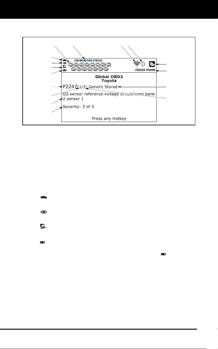
Figure 2. Display Functions
See Figure 2 for the locations of items 1 through 16, below.
1. I/M MONITOR STATUS field - Identifies the I/M Monitor status area.
2. Monitor icons - Indicate which Monitors are supported by the
vehicle under test, and whether or not the associated Monitor has
run its diagnostic testing (Monitor status). A solid green icon
indicates the associated Monitor has completed its diagnostic
testing. A flashing red icon indicates that the vehicle supports the
associated Monitor, but the Monitor has not yet run its diagnostic
testing.
3.
Vehicle icon - When visible, indicates that the Scan Tool is
being powered through the vehicle’s DLC connector.
4.
Link icon - When visible, indicates the Scan Tool is
communicating with the vehicle’s computer.
5. Computer icon - When visible, indicates the Scan Tool is linked
to a personal computer.
6.
Scan Tool Internal Battery icon - When visible, indicates the
Scan Tool batteries are “low” and should be replaced. If the
batteries are not replaced when the battery symbol
is "on", all 3
LEDs will light to warn that the batteries need replacement. No data
will be displayed on screen when all 3 LEDs are lit.
7. DTC Display Area - Displays the Diagnostic Trouble Code (DTC)
number. Each fault is assigned a code number that is specific to that
fault. The DTC number is color-coded as follows:
RED - Indicates the currently displayed DTC is a STORED or
PERMANENT DTC.
YELLOW - Indicates the currently displayed DTC is a PENDING
DTC.
4
3
2
5
8
6
7
1 1516
10
14
11
12
13
9

Scan Tool Controls
BATTERY REPLACEMENT
5
GREEN - In cases where no codes are retrieved, a “No DTCs
are presently stored in the vehicle’s computer” message is
shown in green.
8. Code Number Sequence - The Scan Tool assigns a sequence
number to each DTC that is present in the computer’s memory,
starting with “1.” This number indicates which code is currently
displayed. Code number “1” is always the highest priority code, and
the one for which “Freeze Frame” data has been stored.
If “1” is a “Pending” code, there may or may not be “Freeze
Frame” data stored in memory.
9. Code Enumerator - Indicates the total number of codes retrieved
from the vehicle’s computer.
10. Test Data Display Area - Displays DTC definitions, Freeze Frame
data and other pertinent test information messages.
11. SYSTEM icon - Indicates the system with which the code is
associated:
MIL icon ABS icon SRS icon
12. FREEZE FRAME icon - Indicates that there is Freeze Frame data
from “Priority Code” (Code #1) stored in the vehicle’s computer
memory.
13. Code type - Indicates the type of code being displayed; Generic
Stored, Generic Pending, Generic permanent, etc.
14. Severity - Indicates the level of severity for the priority code (code
number “1”), as follows:
1 - Service should be scheduled and repairs made when
convenient. This DTC typically has no immediate threat to
essential system components in the short term.
2 - Repair immediately if drivability issues are present. Threat to
essential system components if not repaired as soon as possible.
3 - Stop and repair vehicle immediately to prevent interrelated
failures. Harmful and damaging to essential system components.
15.
Bluetooth icon – Indicates communication status with a compat-
ible Innova mobile application (please visit www.innova.com/apps
for more information). A solid blue icon indicates an active Bluetooth
connection has been established. A solid grey icon indicates
Bluetooth is not connected.
16.
Wi-Fi icon – Indicates Wi-Fi communication status. When ON,
indicates the scan tool is linked to a Wi-Fi network. When OFF,
indicates there is no Wi-Fi connection.
BATTERY REPLACEMENT
Replace batteries when the battery symbol is visible on display
and/or the 3 LEDS are all lit and no other data is visible on screen.
1. Locate the battery cover on the back of the Scan Tool.

Scan Tool Controls
BATTERY REPLACEMENT
6
2. Slide the battery cover off (use your fingers).
3. Replace batteries with three AA-size batteries (for longer life, use
Alkaline-type batteries).
4. Reinstall the battery cover on the back of the Scan Tool.
Adjustments After Battery Installation
The first time the Scan Tool is turned on, you must select the desired
display language (English, French or Spanish) and unit of measurement
(Standard or metric) as follows:
5. Press the POWER/LINK
button to turn the Scan Tool “ON.”
The Select Language screen displays.
6. Select the desired display language, then press ENTER
.
The Select Unit screen displays.
7. Select the desired unit of measurement, then press ENTER
The Scan Tool’s Firmware Version screen displays.
After the initial language and unit of measurement selections
are performed, these, as well as other settings, can be
changed as desired. Proceed to “ADJUSTMENTS AND
SETTINGS” on page 51 for further instructions.
Using the Scan Tool
CODE RETRIEVAL PROCEDURE
7
Retrieving and using Diagnostic Trouble Codes (DTCs) fo
r
troubleshooting vehicle operation is only one part of an
overall diagnostic strategy.
CODE RETRIEVAL PROCEDURE
Never replace a part based only on the DTC definition.
Each DTC has a set of testing procedures, instructions and
flow charts that must be followed to confirm the location of
the problem. Always refer to the vehicle's service manual
for detailed testing instructions.
Check your vehicle thoroughly before performing
any test.
ALWAYS observe safety precautions whenever working on a
vehicle.
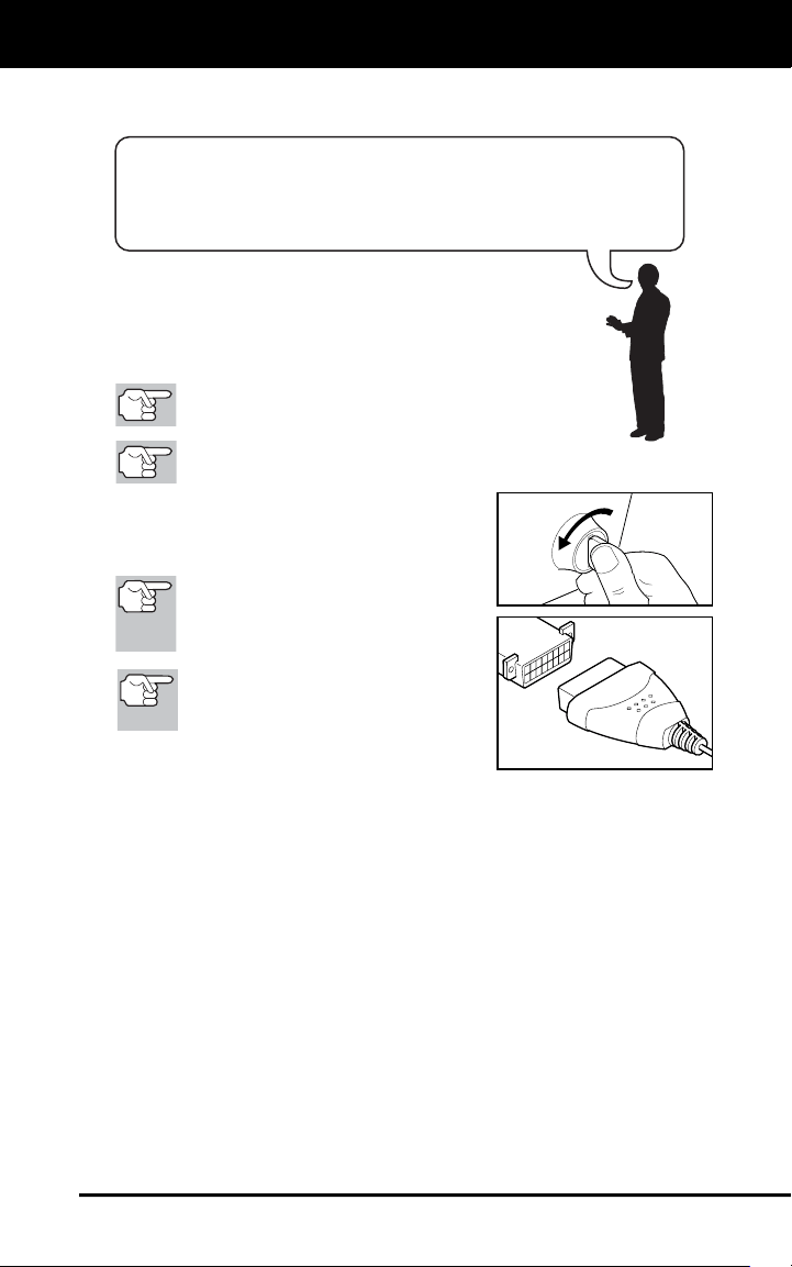
1. Turn the ignition off.
2. Locate the vehicle's 16-pin Data Link
Connector (DLC).
Some DLCs have a plastic cover
that must be removed before
connecting the Scan Tool cable
connector.
If the Scan Tool is ON, turn it OFF
BEFORE connecting the Scan
Tool to the DLC.
3. Connect the Scan Tool to the vehicle’s
DLC. The cable connector is keyed and
will only fit one way.
If you have problems connecting the cable connector to the DLC,
rotate the connector 180°.
If you still have problems, check the DLC on the vehicle and on
the Scan Tool.
4. Turn the ignition on. DO NOT start the engine.
5. When the Scan Tool is properly connected to the vehicle’s DLC, the
unit automatically turns ON.
If the unit does not power on automatically, it may indicate there
is no power present at the vehicle’s DLC connector. Check the
fuse panel and replace any burned-out fuses.
If replacing the fuse(s) does not correct the problem, consult your
vehicle’s repair manual to identify the proper computer (PCM)
fuse/circuit, and perform any necessary repairs before proceeding.
Using the Scan Tool
CODE RETRIEVAL PROCEDURE
8
6. The Scan Tool automatically starts a check of the vehicle’s
computer to determine which type of communication protocol it is
using. When the Scan Tool identifies the computer’s communication
protocol, a communication link is established.
A PROTOCOL is a set of rules and procedures for regulating
data transmission between computers, and between testing
equipment and computers. As of this writing, five different types
of protocols (ISO 9141, Keyword 2000, J1850 PWM, J1850
VPW and CAN) are in use by vehicle manufacturers.
If the Scan Tool fails to link to the vehicle’s computer, a
“Communication Error” message shows.
- Ensure your vehicle is OBD2 compliant.
- Verify the connection at the DLC, and verify the ignition is ON.
- Turn the ignition OFF, wait 5 seconds, then back ON to reset
the computer.
- Press POWER/LINK
to continue.
If the Scan Tool cannot link to the vehicle’s computer after three
attempts, the message “Contact Technical Support” displays.
- Press SYSTEM MENU
to return to the System Menu.
- Turn the ignition off, and
disconnect the Scan Tool.
- Contact Technical Support for
assistance.
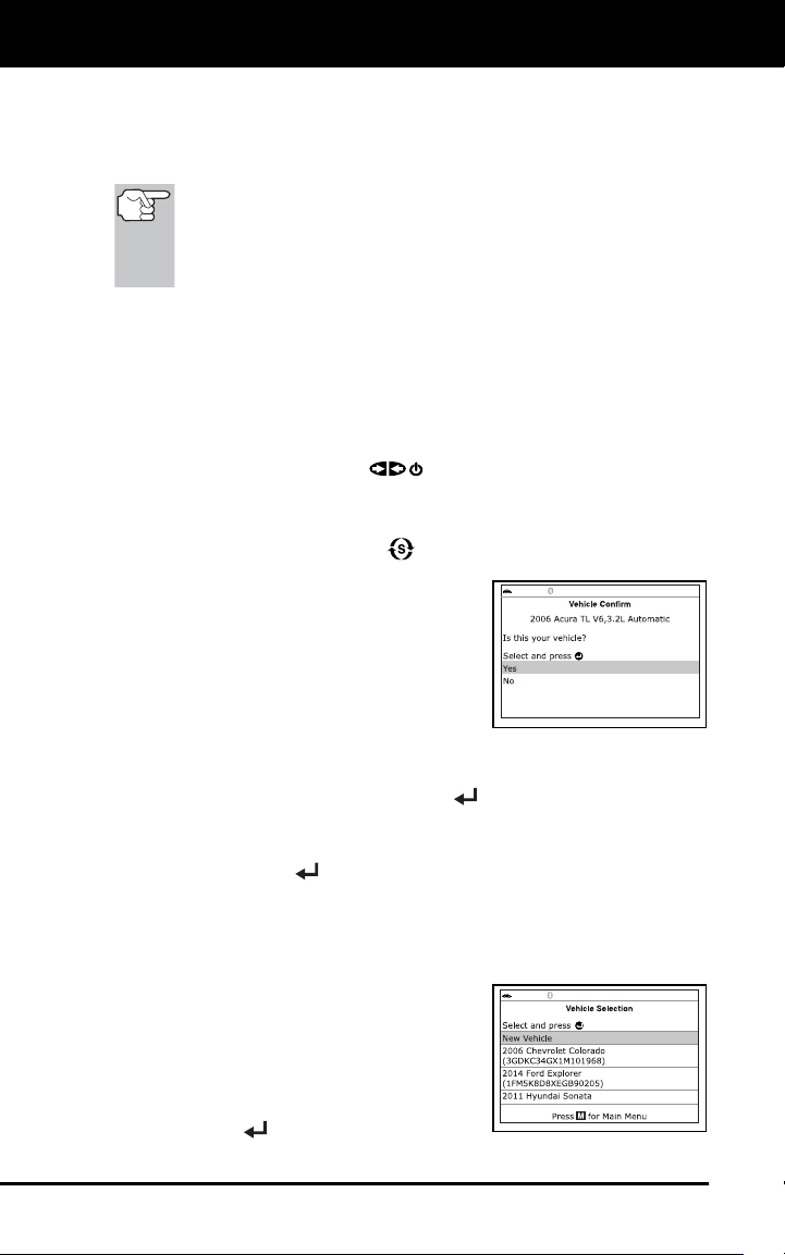
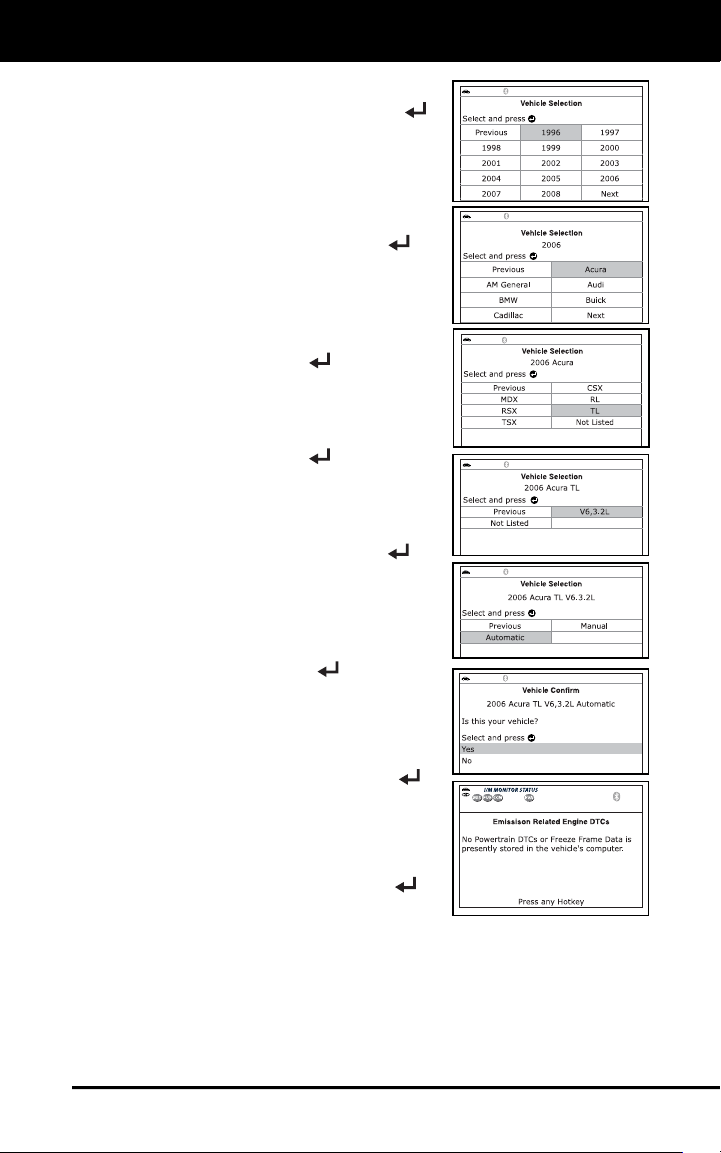
7. If the Scan Tool can decode the Vehicle
Identification Number (VIN) for the
vehicle under test, the Confirm Vehicle
screen displays.
If the information shown is correct for the vehicle under test,
select Yes, then press te ENTER
. Proceed to step 10.
If the information shown is not correct for the vehicle under test,
or if you wish to manually select the vehicle, select No, then
press ENTER
. Proceed to step 8.
If the Scan Tool cannot decode the Vehicle Identification
Number (VIN) for the vehicle under test, the Select Vehicle
screen displays. Proceed to step 8.
8. When No is selected from the Vehicle
information screen, the Select Vehicle
screen displays. The Select Vehicle
screen lists the three most recently
tested vehicles.
To select a previously tested vehicle,
select the desired vehicle, then press
ENTER
. Proceed to step 10.
Using the Scan Tool
CODE RETRIEVAL PROCEDURE
9
To select a new vehicle, select New
Vehicle, then press ENTER
.
Proceed to step 9.
9. When New Vehicle is chosen from the
Select Vehicle screen, the Select Year
screen displays.
Select the desired vehicle model
year, then press ENTER
to
continue.
- The Select Make screen dis-
plays.
Select the desired vehicle make,
then press ENTER
to continue.
- The Select Model screen dis-
plays.
Select the desired vehicle model,
then press ENTER
to continue.
- The Select Engine screen
displays.
Select the desired vehicle engine
size, then press ENTER
to
continue.
- The Select Transmission screen
displays.
Select the desired transmission type,
then press ENTER
to continue.
The Vehicle Information screen
displays.
If the information shown is correct
for the vehicle under test, select
Yes, then press ENTER
.
Proceed to step 10.
If the information shown is not
correct for the vehicle under test, or
if you wish to reselect the vehicle,
select No, then press ENTER
to
return to the Select Year screen.
10. After approximately 10~60 seconds, the Scan Tool will retrieve and
display any Diagnostic Trouble Codes, Monitor Status and Freeze
Frame Data retrieved from the vehicle’s computer memory.
The Scan Tool will display a code only if codes are present. If no
codes are present, the message “No Powertrain DTCs or Freeze
Frame Data presently stored in the vehicle’s computer” displays.
Using the Scan Tool
CODE RETRIEVAL PROCEDURE
10
The Scan Tool is capable of retrieving and storing up to 32
codes in memory, for immediate or later viewing.
11. Refer to DISPLAY FUNCTIONS on page 4 for a description of
display elements.
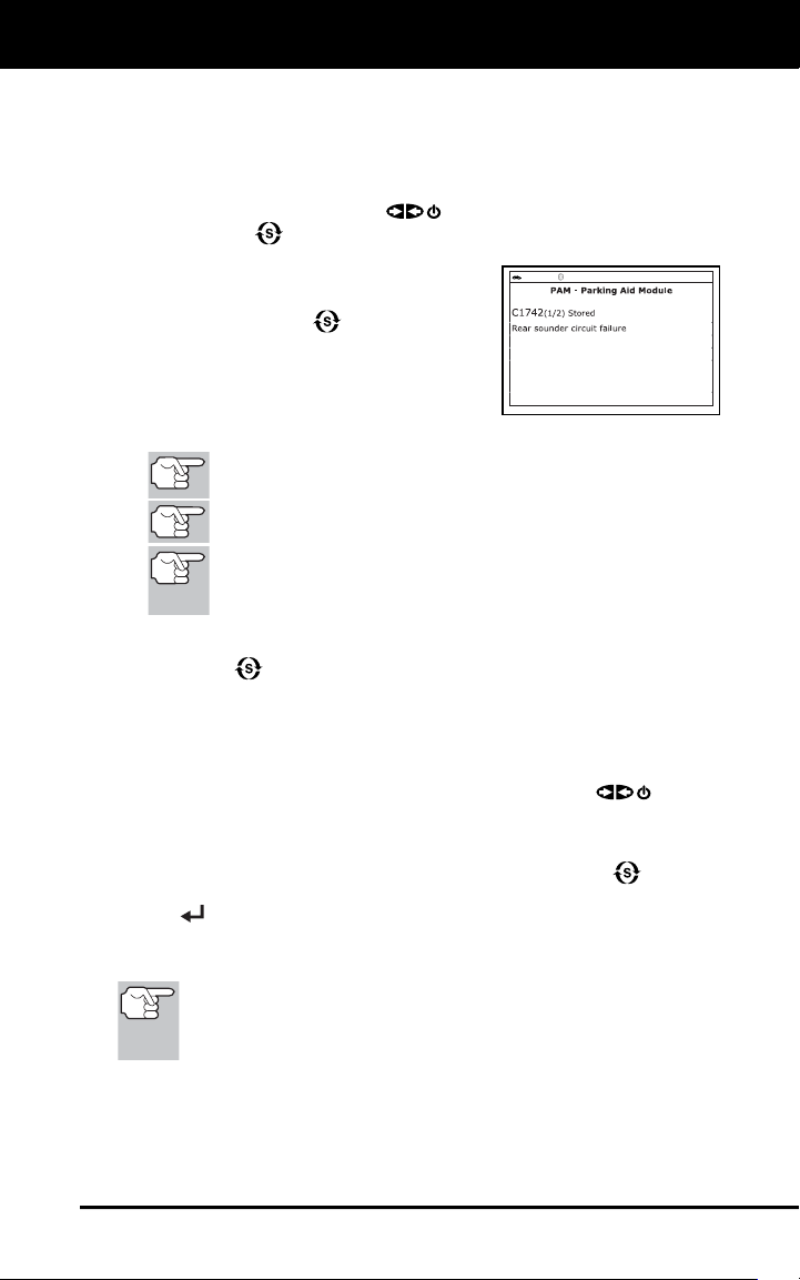
In the case of long code definitions,
a small arrow is shown in the
upper/lower right-hand corner of the
Scan Tool display area to indicate
the presence of additional
information.
If a definition for the currently
displayed code is not available, an
advisory message shows.
12. Read and interpret Diagnostic Trouble Codes/system condition
using the display and the green, yellow and red LEDs.
The green, yellow and red LEDs are used (with the display) as
visual aids to make it easier to determine engine system
conditions.
Green LED – Indicates that all
engine systems are “OK” and
operating normally. All monitors
supported by the vehicle have run
and performed their diagnostic
testing, and no trouble codes are
present. All Monitor icons will be
solid.
Yellow LED – Indicates one of the
following conditions:
A. Green LED – Indicates that all
engine systems are “OK” and
operating normally. All monitors
supported by the vehicle have run
and performed their diagnostic
testing, and no trouble codes are
present. All Monitor icons will be
solid.
B. MONITOR NOT RUN STATUS – If
the display shows a zero (indicating
there are no DTC’s present in the
vehicle’s computer memory), but
the yellow LED is illuminated, it may
be an indication that some of the
Monitors supported by the vehicle
have not yet run and completed
their diagnostic testing. Check the
display for confirmation. All Monitor
icons that are blinking have not yet run and completed their
diagnostic testing; all Monitor icons that are solid have run and
completed their diagnostic testing.
Using the Scan Tool
CODE RETRIEVAL PROCEDURE
11
Red LED – Indicates there is a
problem with one or more of the
vehicle’s systems. The red LED is
also used to indicate that DTC(s)
are present. In this case, the
Malfunction Indicator (Check Engine)
lamp on the vehicle’s instrument
panel will be illuminated.
DTC’s that start with “P0”, “P2” and
some “P3” are considered Generic (Universal). All Generic DTC
definitions are the same on all OBD2 equipped vehicles. The Scan
Tool automatically displays the code definitions (if available) for
Generic DTC’s.
DTC’s that start with “P1” and some “P3” are Manufacturer specific
codes and their code definitions vary with each vehicle
manufacturer.
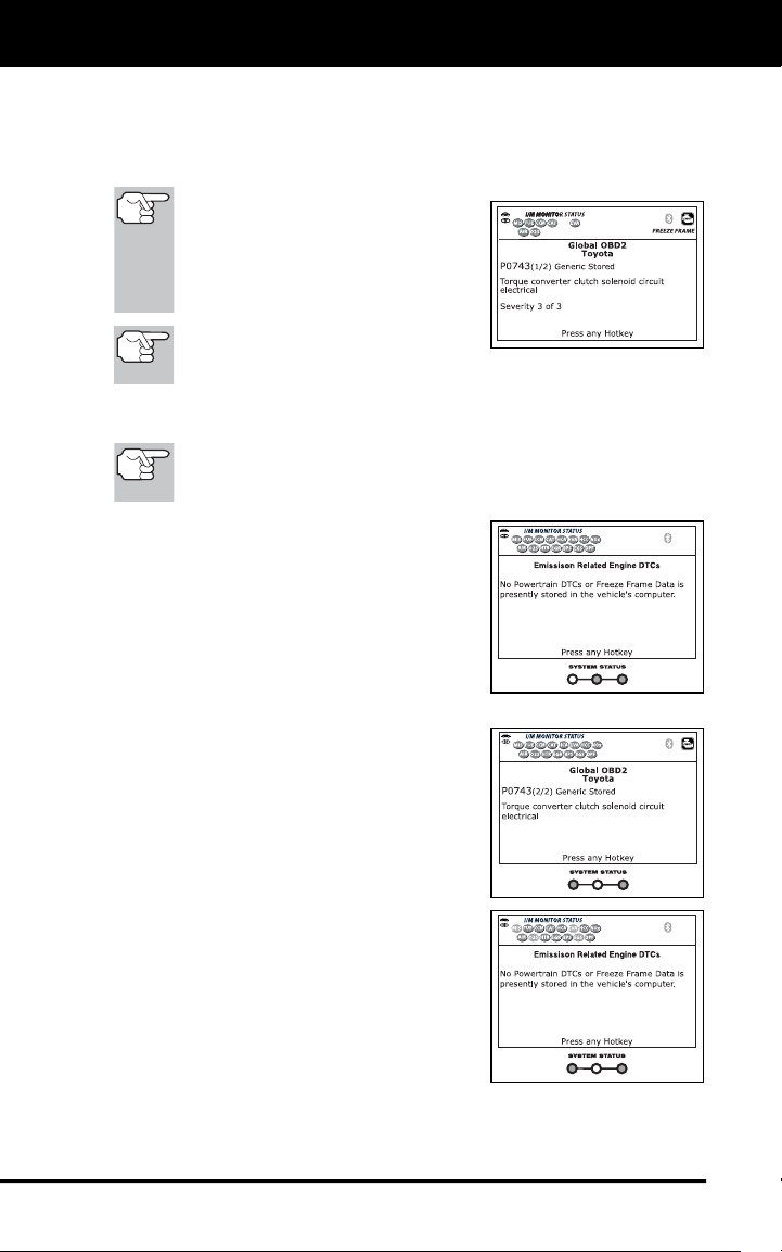
13. If more than one DTC was retrieved, and to view Freeze Frame
Data, press and release DTC/FF, as necessary.
Each time DTC/FF is pressed and released, the Scan Tool will
scroll and display the next DTC in sequence until all DTCs in its
memory have displayed.
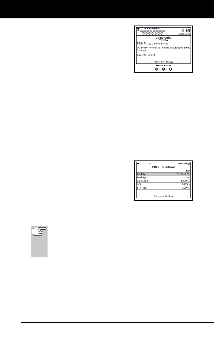
Freeze Frame Data (if available) will display after DTC #1.
In OBD2 systems, when an
emissions-related engine malfunction
occurs that causes a DTC to set, a
record or snapshot of engine
conditions at the time that the
malfunction occurred is also saved in
the vehicle’s computer memory. The
record saved is called Freeze Frame
data. Saved engine conditions include, but are not limited to: engine
speed, open or closed loop operation, fuel system commands,
coolant temperature, calculated load value, fuel pressure, vehicle
speed, air flow rate, and intake manifold pressure.
If more than one malfunction is present that causes more than
one DTC to be set, only the code with the highest priority will
contain Freeze Frame data. The code designated “01” on the
Scan Tool display is referred to as the PRIORITY code, and
Freeze Frame data always refers to this code. The priority
code is also the one that has commanded the MIL on.
14. When the last retrieved DTC has been displayed and DTC/FF is
pressed, the Scan Tool returns to the “Priority” Code.
15. Determine engine system(s) condition by viewing the Scan Tool’s
display for any retrieved Diagnostic Trouble Codes, code definitions and
Freeze Frame data, interpreting the green, yellow and red LEDs.
If DTC’s were retrieved and you are going to perform the repairs
yourself, proceed by consulting the Vehicle’s Service Repair
Manual for testing instructions, testing procedures, and flow
charts related to retrieved code(s).
Using the Scan Tool
THE SYSTEM MENU - VIEWING OEM ENHANCED DTCs (except Ford/Mazda)
12
To prolong battery life, the Scan Tool automatically shuts “Off”
approximately three minutes after it is disconnected from the
vehicle. The DTCs retrieved, Monitor Status and Freeze Frame
data (if any) will remain in the Scan Tool’s memory, and may be
viewed at any time by turning the unit “On”. If the Scan Tool’s
batteries are removed, or if the Scan Tool is re-linked to a
vehicle to retrieve codes/data, any prior codes/data in its
memory are automatically cleared.
THE SYSTEM MENU
The System Menu provides the ability to retrieve “enhanced” DTCs, Anti-
Lock Brake System (ABS), Supplemental Restraint System (SRS) DTCs
and Tire Pressure Monitoring System DTCs for most BMW, Chrysler/Jeep,
Ford/Mazda, GM/Isuzu, Honda/Acura, Hyundai, Mercedes Benz, Nissan,
Toyota/Lexus, Volkswagen and Volvo vehicles. The types of enhanced data
available depends on the vehicle make. You can also return to the Global
OBD2 mode.
Depending on the vehicle under
test, some features and functions
may not be available.
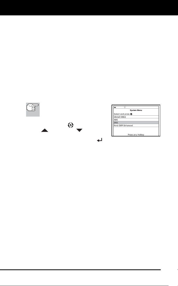
To access the System Menu, press the
SYSTEM MENU
button. Use the
UP
and DOWN
buttons, as
necessary, to highlight the desired
option, then press the ENTER
button to view the selected
information.
To view ABS DTCs: Select ABS from the System Menu. Refer to
VIEWING ABS DTCs on page 15 to view ABS DTCs for your vehicle.
To view SRS DTCs: Select SRS from the System Menu. Refer to
VIEWING SRS DTCs on page 16 to view SRS DTCs for your vehicle.
To view TPMS DTCs: Select TPMS from the System Menu. Refer to
VIEWING TPMS DTCs on page 18 to view TPMS DTCs for your vehicle.
To view OEM enhanced DTCs: Select OEM Enhanced from the
System Menu. Refer to VIEWING OEM ENHANCED DTCs on page 12
to view OEM enhanced DTCs for your vehicle.
To perform a Network Test: Select All Module Scan or Select
Modules, as desired. Refer to NETWORK TEST on page 19 to view
DTCs for other modules.
VIEWING OEM ENHANCED DTCs (except Ford/Mazda)
When (make) OEM Enhanced is chosen from the System Menu, the
Scan Tool retrieves OEM enhanced DTCs from the vehicle’s computer.
1. A “One moment please” message displays while the Scan Tool
retrieves the selected DTCs.
If the Scan Tool fails to link to the vehicle’s computer, a
“Communication Error” message shows.
Using the Scan Tool
VIEWING OEM ENHANCED DTCs (Ford/Mazda only)
13
- Ensure your vehicle is OBD2 compliant.
- Verify the connection at the DLC, and verify the ignition is ON.
- Turn the ignition OFF, wait 5 seconds, then back ON to reset
the computer.
- Press POWER/LINK
to continue.
If the Scan Tool cannot link to the vehicle’s computer after three
attempts, the message “Contact Technical Support” displays.
- Press SYSTEM MENU
to return to the System Menu.
- Turn the ignition off, and disconnect the Scan Tool.
- Contact Technical Support for assistance.
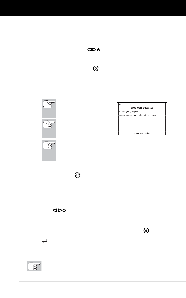
2. Refer to DISPLAY FUNCTIONS on page 3 for a description of LCD
display elements.
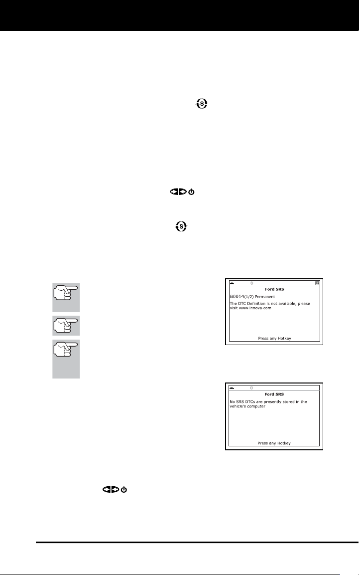
If the definition for the cur-
rently displayed code is not
available, an advisory mes-
sage shows.
I/M MONITOR STATUS
icons are not displayed
when viewing enhanced
DTCs.
In the case of long code definitions, a small arrow is
shown in the upper/lower right-hand corner of the code
display area to indicate the presence of additional
information.
If no codes are present, the message “No OEM Enhanced DTC’s
are presently stored in the vehicle’s computer” shows. Press
SYSTEM MENU
to return to the System Menu.
3. If more than one code was retrieved press DTC/FF, as necessary,
to display additional codes one at a time.
Whenever the Scroll function is used to view additional codes,
the Scan Tool’s communication link with the vehicle’s computer
disconnects. To re-establish communication, press POWER/
LINK
again.
4. When the last retrieved DTC has been displayed and DTC/FF is
pressed, the Scan Tool returns to the “Priority” Code.
To exit the enhanced mode, press SYSTEM MENU to return
to the System Menu. Select Global OBD, then press ENTER
to return to the Global OBD2 mode.
VIEWING OEM ENHANCED DTCs (Ford/Mazda only)
Mazda Enhanced DTCs are available for Mazda-branded
Ford vehicles only.
Using the Scan Tool
VIEWING OEM ENHANCED DTCs (Ford/Mazda only)
14
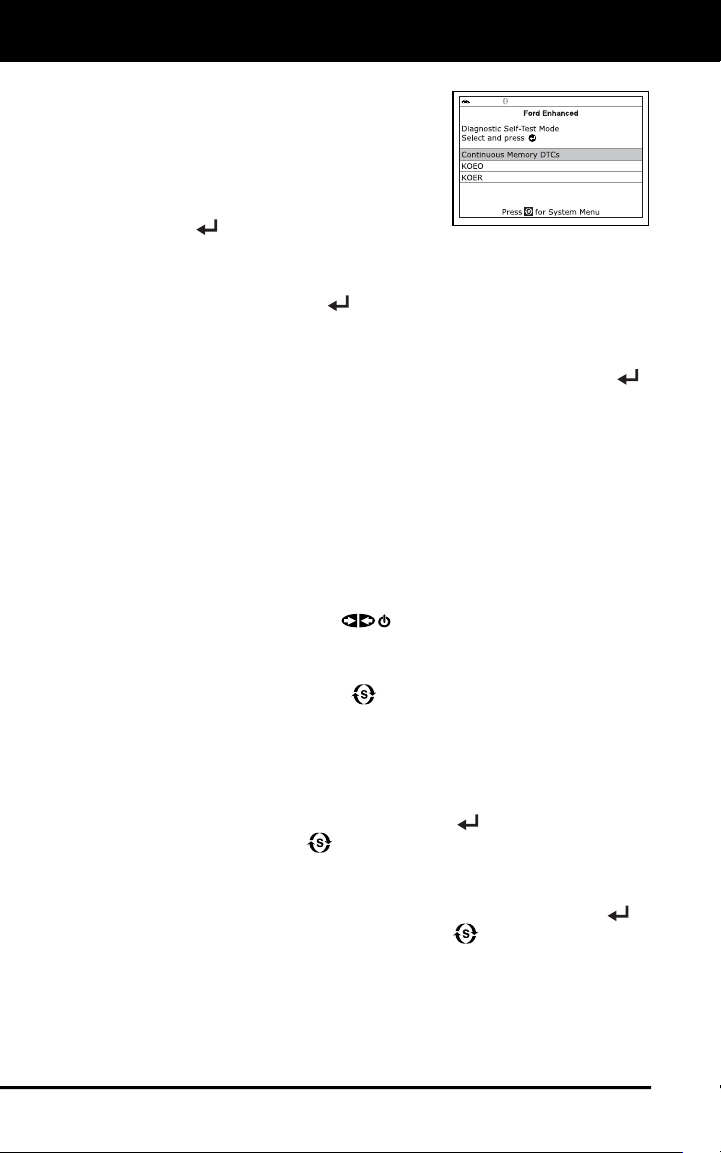
When Ford OEM Enhanced is chosen from
the System Menu, the Ford OEM Enhanced
menu displays. You may view DTCs for
either the “Continuous Memory Test”,
“KOEO (Key On Engine Off) Test” or
“KOER (Key On Engine Running) Test.”
1. Select the desired option, then press
ENTER
.
If KOER is selected, an advisory message shows.
- Start and warm the engine to normal operating temperature,
then press ENTER
. Proceed to step 3.
2. If KOEO or Continuous Memory is selected, an “instructional”
message shows.
Turn the ignition OFF, then back ON. Press ENTER .
Proceed to step 3.
3. A “One moment please” message displays while the test is in
progress.
If the Scan Tool fails to link to the vehicle’s computer, a
“Communication Error” message shows.
- Ensure your vehicle is OBD2 compliant.
- Verify the connection at the DLC, and verify the ignition is ON.
- Turn the ignition OFF, wait 5 seconds, then back ON to reset
the computer.
- Press POWER/LINK
to continue.
If the Scan Tool cannot link to the vehicle’s computer after three
attempts, the message “Contact Technical Support” displays.
- Press SYSTEM MENU
to return to the System Menu.
- Turn the ignition off, and disconnect the Scan Tool.
- Contact Technical Support for assistance.
If the KOER Test was selected, and the vehicle’s engine is not
running, an advisory message shows.
- Start the engine and press ENTER
to try again, or, press
SYSTEM MENU
to return to the System Menu.
If the KOEO Test was selected, and the vehicle’s engine is
running, an advisory message shows.
- Turn the ignition OFF then back ON and press ENTER
to
try again, or, press SYSTEM MENU
to return to the System
Menu.
4. If the KOER test was selected, an “instructional” message shows.
Turn the steering wheel to the left, then release.
Press and release the brake pedal.
Using the Scan Tool
VIEWING ABS DTCs
15
Cycle the overdrive switch (if equipped).
A “One moment please” message displays while the test is in
progress.
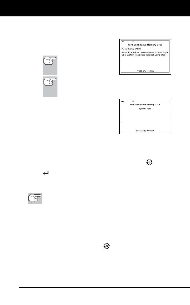
5. Refer to DISPLAY FUNCTIONS on
page 3 for a description of LCD display
elements.
I/M MONITOR STATUS
icons are not displayed
when viewing enhanced
DTCs.
In the case of long code definitions, a small arrow is
shown in the upper/lower right-hand corner of the code
display area to indicate the presence of additional
information.
If no codes are present, a “System
Pass” message displays. Press any
Hotkey.
6. If more than one code was retrieved
press DTC/FF to display additional
codes one at a time.
7. When the last retrieved DTC has been displayed and DTC/FF is
pressed, the Scan Tool returns to the “Priority” Code.
To view additional enhanced DTCs, repeat steps 1 through 5,
above.
To exit the enhanced mode, press SYSTEM MENU to return
to the System Menu. Select Global OBD, then press ENTER
to return to the Global OBD2 mode.
VIEWING ABS DTCs
Refer to the manufacturer’s website for vehicle makes covered.
Reading ABS DTCs
1. When ABS is chosen from the System Menu, a "One moment
please" message displays while the Scan Tool retrieves the selected
DTCs.
If ABS functionality is not supported, an advisory message
shows. Press SYSTEM MENU
to return to the System Menu.
If the Scan Tool fails to link to the vehicle’s computer, a
"Communication Error" message shows.
- Ensure your vehicle is OBD2 compliant.
- Verify the connection at the DLC, and verify the ignition is ON.
Using the Scan Tool
VIEWING SRS DTCs
16
- Turn the ignition OFF, wait 5 seconds, then back ON to reset
the computer.
- Press POWER/LINK
to continue.
If the Scan Tool cannot link to the vehicle’s computer after three
attempts, the message “Contact Technical Support” displays.
- Press SYSTEM MENU
to return to the System Menu.
- Turn the ignition off, and disconnect the Scan Tool.
- Contact Technical Support for assistance.
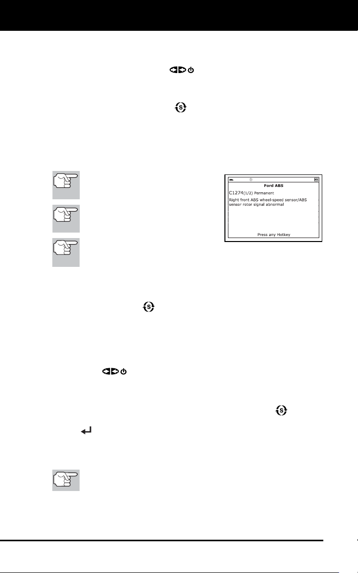
2. Refer to DISPLAY FUNCTIONS on page 3 for a description of LCD
display elements.
If the definition for the currently
displayed code is not available, an
advisory message shows.
I/M MONITOR STATUS icons are
not displayed when viewing ABS
DTCs.
In the case of long code
definitions, a small arrow is shown in the upper/lower right-
hand corner of the code display area to indicate the presence
of additional information.
If no codes are present, the message "No ABS DTC’s are
presently stored in the vehicle’s computer" shows. Press
SYSTEM MENU
to return to the System Menu.
3. If more than one code was retrieved press DTC/FF to display
additional codes one at a time.
Whenever the Scroll function is used to view additional codes,
the Scan Tool’s communication link with the vehicle’s computer
disconnects. To re-establish communication, press POWER/
LINK
again.
4. When the last retrieved DTC has been displayed and DTC/FF is
pressed, the Scan Tool returns to the “Priority” Code.
To exit the enhanced mode, press SYSTEM MENU to return
to the System Menu. Select Global OBD, then press ENTER
to return to the Global OBD2 mode.
VIEWING SRS DTCs
Refer to the manufacturer’s website for vehicle makes covered.
Using the Scan Tool
VIEWING SRS DTCs
17
Reading SRS DTCs
1. When SRS DTCs is chosen from the System Menu, a "One moment
please" message displays while the Scan Tool retrieves the selected
DTCs.
If SRS functionality is not supported, an advisory message
shows. Press SYSTEM MENU
to return to the System Menu.
If the Scan Tool fails to link to the vehicle’s computer, a
"Communication Error" message shows.
- Ensure your vehicle is OBD2 compliant.
- Verify the connection at the DLC, and verify the ignition is ON.
- Turn the ignition OFF, wait 5 seconds, then back ON to reset
the computer.
- Press POWER/LINK
to continue.
If the Scan Tool cannot link to the vehicle’s computer after three
attempts, the message “Contact Technical Support” displays.
- Press SYSTEM MENU
to return to the System Menu.
- Turn the ignition off, and disconnect the Scan Tool.
- Contact Technical Support for assistance.
2. Refer to DISPLAY FUNCTIONS on page 3 for a description of LCD
display elements.
If the definition for the currently
displayed code is not available, an
advisory message shows.
I/M MONITOR STATUS icons are not
displayed when viewing SRS DTCs.
In the case of long code
definitions, a small arrow is shown in the upper/lower right-
hand corner of the code display area to indicate the presence
of additional information.
If no codes are present, the
message "No SRS DTC’s are
presently stored in the vehicle’s
computer" shows.
3. If more than one code was retrieved
press DTC/FF to display additional
codes one at a time.
Whenever the Scroll function is used to view additional codes,
the Scan Tool’s communication link with the vehicle’s computer
disconnects. To re-establish communication, press POWER/
LINK
again.
4. When the last retrieved DTC has been displayed and DTC/FF is
pressed, the Scan Tool returns to the “Priority” code.
Using the Scan Tool
VIEWING TPMS DTCs
18
To exit the enhanced mode, press SYSTEM MENU to return
to the System Menu. Select Global OBD, then press ENTER
to return to the Global OBD2 mode.
VIEWING TPMS DTCs
Refer to the manufacturer’s website for vehicle makes covered.
Reading TPMS DTCs
1. When TPMS DTCs is chosen from the System Menu, a "One
moment please" message displays while the Scan Tool retrieves the
selected DTCs.
If TPMS functionality is not supported, an advisory message
shows. Press SYSTEM MENU
to return to the System Menu.
If the Scan Tool fails to link to the vehicle’s computer, a
"Communication Error" message shows.
- Ensure your vehicle is OBD2 compliant.
- Verify the connection at the DLC, and verify the ignition is ON.
- Turn the ignition OFF, wait 5 seconds, then back ON to reset
the computer.
- Press POWER/LINK
to continue.
If the Scan Tool cannot link to the vehicle’s computer after three
attempts, the message “Contact Technical Support” displays.
- Press SYSTEM MENU
to return to the System Menu.
- Turn the ignition off, and disconnect the Scan Tool.
- Contact Technical Support for assistance.
2. Refer to DISPLAY FUNCTIONS on
page 3 for a description of LCD display
elements.
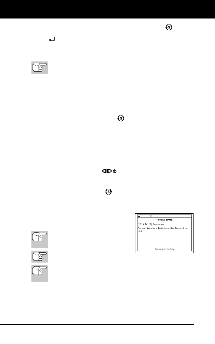
If the definition for the currently
displayed code is not available, an
advisory message shows.
I/M MONITOR STATUS icons are not
displayed when viewing SRS DTCs.
In the case of long code definitions, a small arrow is shown in
the upper/lower right-hand corner of the code display area to
indicate the presence of additional information.
If no codes are present, the message "No TPMS DTC’s are
presently stored in the vehicle’s computer" shows.
3. If more than one code was retrieved press DTC/FF to display
additional codes one at a time.
Using the Scan Tool
NETWORK TEST
19
Whenever the Scroll function is used to view additional codes,
the Scan Tool’s communication link with the vehicle’s computer
disconnects. To re-establish communication, press
POWER/LINK
again.
4. When the last retrieved DTC has been displayed and DTC/FF is
pressed, the Scan Tool returns to the “Priority” code.
To exit the enhanced mode, press SYSTEM MENU to return
to the System Menu. Select Global OBD, then press ENTER
to return to the Global OBD2 mode.
NETWORK TEST
The Network Test lets you perform a scan of all vehicle modules, or of a
single selected module, to retrieve DTCs associated with the module(s).
To scan all modules:
1. Select All Module Scan from the System Menu, then press ENTER
.
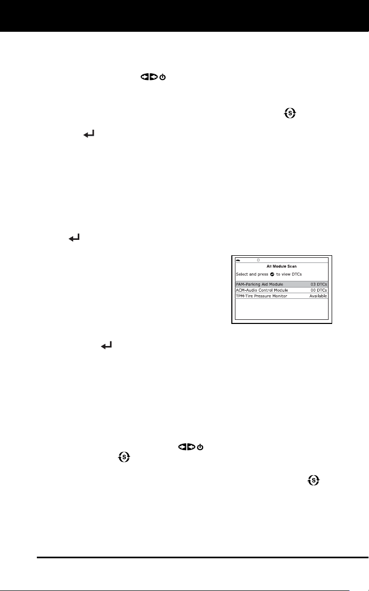
A “One moment please” message
displays while the Scan Tool scans
all available modules.
When the scan is complete, the
Available Systems screen displays.
The screen shows the number of
DTCs recorded for each available
module.
2. Select the module for which you wish to view DTCs, then press
ENTER
. A “One moment please” message displays while the
requested DTCs are retrieved.
If the Scan Tool fails to link to the selected module, a
“Communication Error” message shows.
- Ensure your vehicle is OBD2 compliant.
- Verify the connection at the DLC, and verify the ignition is ON.
- Turn the ignition OFF, wait 5 seconds, then back ON to reset
the computer.
- Press POWER/LINK
to continue, or, press System
Menu
to return to the System Menu.
If the selected module does not support the “Read DTC” function,
an advisory message displays. Press System Menu
to
return to the System Menu, or, press M to access the Main
Menu.
Using the Scan Tool
NETWORK TEST
20
3. Refer to DISPLAY FUNCTIONS on
page 4 for a description of LCD display
elements.
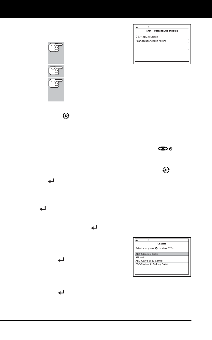
If the definition for the
currently displayed code is
not available, an advisory
message shows.
I/M MONITOR STATUS icons are not displayed when
using the Network Test function.
In the case of long code definitions, a small arrow is
shown in the upper/lower right-hand corner of the code
display area to indicate the presence of additional
information.
If no codes are present, the message "No (system name) DTC’s are
presently stored in the vehicle’s computer" shows. Press System
Menu
to return to the System Menu.
4. If more than one code was retrieved press DTC/FF to display
additional codes one at a time.
Whenever the Scroll function is used, the Scan Tool’s
communication link with the vehicle’s computer disconnects. To
re-establish communication, press POWER/LINK
again.
5. When the last retrieved DTC has been displayed and DTC/FF is
pressed, the Scan Tool returns to the first code.
To exit the enhanced mode, Press System Menu to return
to the System Menu. Select Global OBD, then press ENTER
to return to the Global OBD2 mode.
To scan a selected module:
1. Choose Select Modules from the System Menu, then press ENTER
.
If the Select Group screen displays, select the group (Drive,
Chassis, Body, etc.) containing the module you wish to scan,
then press ENTER
. Proceed to step 2.
If the Select Group screen does not
display, proceed to step 2.
2. The Available Systems screen displays.
Select the desired module, then press
ENTER
.
A “One moment please” message
displays while the requested DTCs
are retrieved.
3. Select the module for which you wish to view DTCs, then press
ENTER
. A “One moment please” message displays while the
requested DTCs are retrieved.
If the Scan Tool fails to link to the selected module, a
“Communication Error” message shows.
Using the Scan Tool
ERASING DIAGNOSTIC TROUBLE CODES (DTCs)
21
- Ensure your vehicle is OBD2 compliant.
- Verify the connection at the DLC, and verify the ignition is ON.
- Turn the ignition OFF, wait 5 seconds, then back ON to reset
the computer.
- Press POWER/LINK
to continue, or, press System
Menu
to return to the System Menu.
If the selected module does not
support the “Read DTC” function, an
advisory message displays. Press
System Menu
to return to the
System Menu, or, press M to
access the Main Menu.
4. Refer to DISPLAY FUNCTIONS on
page 4 for a description of LCD display
elements.
If the definition for the currently displayed code is not available,
an advisory message shows.
I/M MONITOR STATUS icons are not displayed when
using the Network Test function.
In the case of long code definitions, a small arrow is shown
in the upper/lower right-hand corner of the code display
area to indicate the presence of additional information.
If no codes are present, the message "No (system name) DTC’s are
presently stored in the vehicle’s computer" shows. Press System
Menu
to return to the System Menu.
5. If more than one code was retrieved press DTC/FF to display
additional codes one at a time.
Whenever the Scroll function is used, the Scan Tool’s
communication link with the vehicle’s computer disconnects. To
re-establish communication, press POWER/LINK
again.
6. When the last retrieved DTC has been displayed and DTC/FF is
pressed, the Scan Tool returns to the first code.
To exit the enhanced mode, press System Menu
to return
to the System Menu. Select Global OBD, then press ENTER
to return to the Global OBD2 mode.
ERASING DIAGNOSTIC TROUBLE CODES (DTCs)
When the Scan Tool’s ERASE function is used to erase DTCs
from the vehicle's on-board computer, "Freeze Frame" data
and manufacturer-specific-enhanced data are also erased.
"Permanent" DTCs ARE NOT erased by the ERASE function.
If you plan to take the vehicle to a Service Center for repair, DO NOT
erase the codes from the vehicle's computer. If the codes are erased,
valuable information that might help the technician troubleshoot the
problem will also be erased.
Using the Scan Tool
ERASING DIAGNOSTIC TROUBLE CODES (DTCs)
22
Erase DTCs from the computer's memory as follows:
When DTCs are erased, the I/M Readiness Monitor Status
program resets the status of all Monitors to a not run condition. To
set all Monitors to a DONE status, an OBD2 Drive Cycle must be
performed.
1. If not connected already, connect the
Scan Tool to the vehicle's DLC, and
turn the ignition "On.” (If the Scan Tool
is already connected and linked to the
vehicle's computer, proceed directly to
step 3. If not, continue to step 2.)
2. Perform the Code Retrieval procedure
as described on page 7.
To erase OBD2 DTCs: Wait until
the codes are displayed, then
proceed to step 3.
To erase enhanced or ABS, SRS,
TPMS or Network DTCs: Press SYSTEM MENU
to display
the System Menu. Select the desired option, then press ENTER
. Perform the appropriate Code Retrieval procedure and then
proceed to step 3.
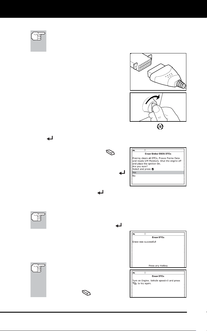
3. Press and release ERASE
. A
confirmation message shows.
If you are sure you want to proceed,
select Yes, then press ENTER
to continue.
If you do not want to proceed, select
No, then press ENTER
to cancel the erase procedure.
4. If you chose to erase DTCs, a “One moment please…” message
displays while the erase function is in progress.
If the vehicle’s engine is running, an advisory message shows.
Turn the engine OFF, then turn the ignition back to ON. DO NOT
start the engine. Press ENTER
to continue.
If the erase was successful, a
confirmation message shows. The
Scan Tool automatically relinks to
the vehicle’s computer after 3
seconds.
If the erase was not successful
and ECU error code $22 is
present, an advisory message
displays. Start the engine and
maintain vehicle speed at 0, then
press ERASE
to try again.

Using the Scan Tool
ABOUT REPAIRSOLUTIONS 2®
23
If the erase was not successful, an advisory message shows on
the display indicating the erase request was sent to the vehicle’s
computer. The Scan Tool automatically relinks to the vehicle’s
computer after 3 seconds.
Erasing DTCs does not fix the problem(s) that caused the
code(s) to be set. If proper repairs to correct the problem that
caused the code(s) to be set are not made, the code(s) will
appear again (and the Check Engine Light will illuminate) as
soon as the vehicle is driven long enough for its Monitors to
complete their testing.
ABOUT REPAIRSOLUTIONS 2®
RepairSolutions 2® is a web-based service created to assist both Do-It-
Yourself and Professional technicians in quickly and accurately
diagnosing and repairing today’s vehicles. RepairSolutions 2 allows you
to view and save the diagnostic data retrieved from a vehicle’s on-board
computer(s) using your Code Reader. At the core of RepairSolutions 2
is an extensive knowledge database, developed by compiling and
analyzing years worth of “real world” vehicle service data.
RepairSolutions 2 builds on manufacturer-recommended diagnostic and
repair information by providing verified, vehicle-specific fixes supplied by
ASE technicians across the country. RepairSolutions 2 also provides
access to an extensive knowledge database including:
Verified Fixes – Find the most likely fixes reported and verified by
ASE Technicians for the retrieved DTCs.
Repair Instructions – View available repair instructions to properly
perform the fix.
Video Tutorials – Watch repair video tutorials for valuable repair
tips.
Technical Service Bulletins – Research known problems reported
by vehicle manufacturers.
Safety Recalls – Research known safety concerns applicable to a
vehicle.
And much more. Please visit www.innova.com for additional information.
Hardware Requirements:
Innova Scan Tool with Bluetooth/WiFi
Android or iOS Smart Device
Accessing RepairSolutions 2®
1. Download and install the RepairSolutions 2® app from the App
Store (for iOS devices) or Google Play (for Android devices).
2. Launch the RepairSolutions 2 app and log in to your account.
If you have not yet established an account, you must register for
a FREE RepairSolutions 2 account before proceeding.

Using the Scan Tool
CONNECTING TO BLUETOOTH / WIFI
24
3. Connect the Code Reader to a vehicle and establish a Bluetooth or
WiFi connection with your Smart Device (refer to CONNECTING TO
BLUETOOTH / WIFI, below). Be sure your Smart Device is
connected to an available WiFi network.
The RepairSolutions 2 app will store two WiFi configurations
only.
4. Retrieve diagnostic data (refer to CODE RETRIEVAL PROCEDURE
on page 7 for details).
5. The RepairSolutions 2 app automatically displays a report based on
the retrieved diagnostic data.
If the Code Reader is not connected to WiFi or Bluetooth,
vehicle data will not be saved.
CONNECTING TO BLUETOOTH / WIFI
Launch the RepairSolutions2 app an follow the prompts to establish
Bluetooth and (optionally) WiFi connections, as follows:
1. Launch the RepairSolutions2 app. Select Wifi Tools Settings from
the menu. Power on your Code Reader, then select from the list of
available devices.
2. When Bluetooth pairing is complete, a confirmation screen displays.
Click Continue.
If a Bluetooth connection cannot be established, an advisory
message displays. Tap Try Again to repeat the pairing process.
3. Follow the on-screen prompts to connect to an available WiFi
network.
You can automatically connect to the network your Smart Device
is currently connected to, or you can manually connect to
another available network.
Note that only 2.4GHz networks are supported.
If you do not wish to connect to a WiFi network at this time, tap
SKIP.
4. When WiFi pairing is complete, a confirmation screen displays. Click
Continue to view the “Setup Complete” message, then click
Continue to enter RepairSolutions2.
If a WiFi connection cannot be established, an advisory
message displays. Tap Try Again to repeat the pairing process.
Live Data Mode
VIEWING LIVE DATA
25
The Scan Tool lets you view and/or record "real-time" Live Data. This
information includes values (volts, rpm, temperature, speed etc.) and
system status information (open loop, closed loop, fuel system status, etc.)
generated by the various vehicle sensors, switches and actuators. These
are the same signal values generated by the sensors, actuators, switches
and/or vehicle system status information used by the vehicle's computer
when calculating and conducting system adjustments and corrections.
The real time (Live Data) vehicle operating information (values/status)
that the computer supplies to the Scan Tool for each sensor, actuator,
switch, etc. is called Parameter Identification (PID) Data.
Each PID (sensor, actuator switch, status, etc.) has a set of operating
characteristics and features (parameters) that serve to identify it. The
Scan Tool displays this information for each sensor, actuator, switch or
status that is supported by the vehicle under test.
WARNING: If the vehicle must be driven in order to perform a
troubleshooting procedure, ALWAYS have a second person
help you. One person should drive the vehicle while the other
person observes the Scan Tool data. Trying to drive and
operate the Scan Tool at the same time is dangerous, and
could cause a serious traffic accident.
VIEWING LIVE DATA
1. While linked to the vehicle, start the engine, then press LD.
2. A “One moment please . . .” message displays while the Scan Tool
establishes communication with the vehicle.
If the Scan Tool fails to establish communication with the vehicle,
a “Communication Error” message displays.
- Ensure your vehicle is OBD2 compliant.
- Verify the connection at the DLC, and verify the ignition is ON.
- Turn the ignition OFF, wait 5 seconds, then back ON to reset
the computer.
- Press ENTER
to continue.
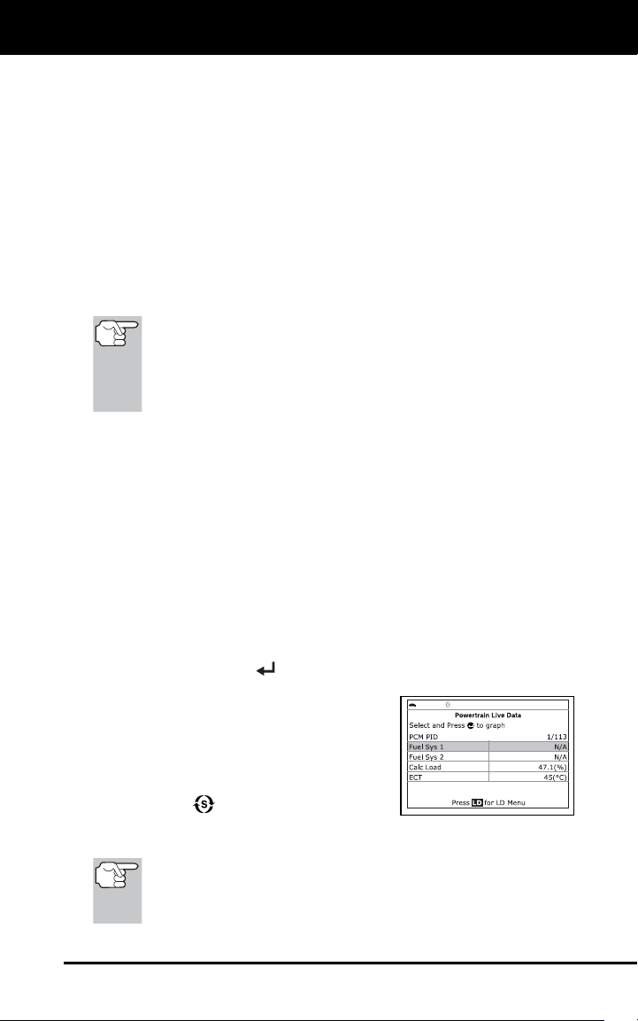
3. Real-time Live Data (PID) information
supported by the vehicle under test
displays.
If Live Data is not supported by the
vehicle under test, an advisory
message displays. Press SYSTEM
MENU
to return to the System
Menu. Live Data is not available for
your vehicle.
Remember, what you are viewing is "real-time" Live Data. The
values (volts, rpm, temperature, vehicle speed, system status etc)
for the various PIDS displayed may change as the vehicle's
operating conditions change.
Live Data Mode
CUSTOMIZING LIVE DATA (PIDs)
26
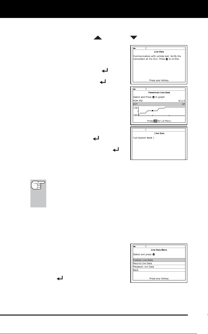
4. Only a limited amount of PID data can be displayed on the screen at
one time. If additional PID data is available, a small arrow is shown
on the display. Press UP
and DOWN , as necessary, to view
all available PID data.
If communication with the vehicle is
lost while viewing Live Data, an
advisory message displays.
5. Press and release ENTER
to view
the currently selected PID in “graph” mode.
Press and release ENTER
again to
return to the PID list.
You can display a maximum of two
PIDs in "graph" mode at any given
time.
With two PID shown in "graph"
mode, press and hold LD to
superimpose one graph on the other.
Release LD to separate the graphs.
6. Press and hold ENTER
to view the
“expanded” definition for the currently
selected PID. Release ENTER
to
return to the PID list.
7. If you experience vehicle problems, view and/or compare the Live
Data (PID) information displayed on the Scan Tool to specifications
in the vehicle's repair manual.
If desired, you can "customize" the Live Data display to show only
those PIDs you are interested in viewing. See Customizing Live
Data (PIDs) below for details. You may also choose to "capture"
(record) Live Data for later viewing. See RECORDING
(CAPTURING) LIVE DATA on page 28 for details.
CUSTOMIZING LIVE DATA (PIDs)
You can customize the Live Data display by placing the Scan Tool in
"Custom Live Data" mode and selecting only the PIDs that you wish to
display.
1. With the Scan Tool in Live Data mode
(see VIEWING LIVE DATA on page 25),
press and hold LD until the Live Data
Menu displays, then release.
2. Select Custom Live Data, then press
ENTER
.
If the Scan Tool fails to establish communication with the vehicle,
a “Communication Error” message displays.
- Ensure your vehicle is OBD2 compliant.
Live Data Mode
CUSTOMIZING LIVE DATA (PIDs)
27
- Verify the connection at the DLC, and verify the ignition is ON.
- Turn the ignition OFF, wait 5 seconds, then back ON to reset
the computer.
- Press POWER/LINK
to continue.
If Live Data is not supported by the vehicle under test, an
advisory message displays. Press SYSTEM MENU
to return
to the System Menu.
If custom Live Data was previously configured, the Select PIDs
to Use screen displays.
- To use the existing custom Live data selections, select Use
existing PIDs, then press ENTER
. Proceed to step 5.
- To configure new custom Live
Data, select Select new PIDs,
then press ENTER
. The
Custom Live Data menu displays.
Proceed to step 3.
If custom Live Data was not
previously selected, the Custom
Live Data menu displays. Proceed
to step 3.
3. Press UP
and DOWN to scroll through the available PIDs.
When a PID you wish to display is highlighted, press ENTER
(a
"checkmark" shows to confirm your selection). Repeat until only the
PIDs you want to display have all been selected.
To deselect a PID, highlight the PID, then press ENTER .
The checkmark is removed.
4. When you are finished making your selection(s), press LD to
continue.
If no PIDs have been selected, an advisory message displays.
Press ENTER
to return to the Custom Live Data menu.
5. The Scan Tool is now in "Custom Live Data" mode. Only the PIDs
you selected are shown.
To change the current custom Live
Data selections, select Reselect
PIDs, then press ENTER
to
return to the Custom Live Data
menu. Repeat step 3.
6. To exit the "Custom Live Data" mode,
press LD to return to the Live Data
Menu.
Live Data Mode
RECORDING (CAPTURING) LIVE DATA
28
RECORDING (CAPTURING) LIVE DATA
You can record and save several frames of Live Data information for
each PID supported by the vehicle in the Scan Tool's memory.
There are two ways that the Scan Tool can record Live Data:
Record by DTC Trigger
Record by Manual Trigger
If POWER/LINK
is pressed at any time while in Live
Data mode, any recorded Live Data will be erased from the
Scan Tool’s memory.
Record by DTC Trigger
This function automatically records Live Data information when a DTC
sets and saves it in the Scan Tool’s memory. The recorded data can be
a valuable troubleshooting aid, particularly if you are experiencing a fault
that is causing a DTC to set. The Scan Tool can record approximately
100 frames of Live Data.
1. With the Scan Tool in Live Data mode (see VIEWING LIVE DATA
on page 25), press and hold LD until the Live Data Menu displays,
then release.
2. Select Record Live Data, then press ENTER
.
The Record Live Data Menu displays.
If the Scan Tool fails to establish communication with the vehicle,
a “Communication Error” message displays.
- Ensure your vehicle is OBD2 compliant.
- Verify the connection at the DLC, and verify the ignition is ON.
- Turn the ignition OFF, wait 5 seconds, then back ON to reset
the computer.
- Press POWER/LINK
to continue.
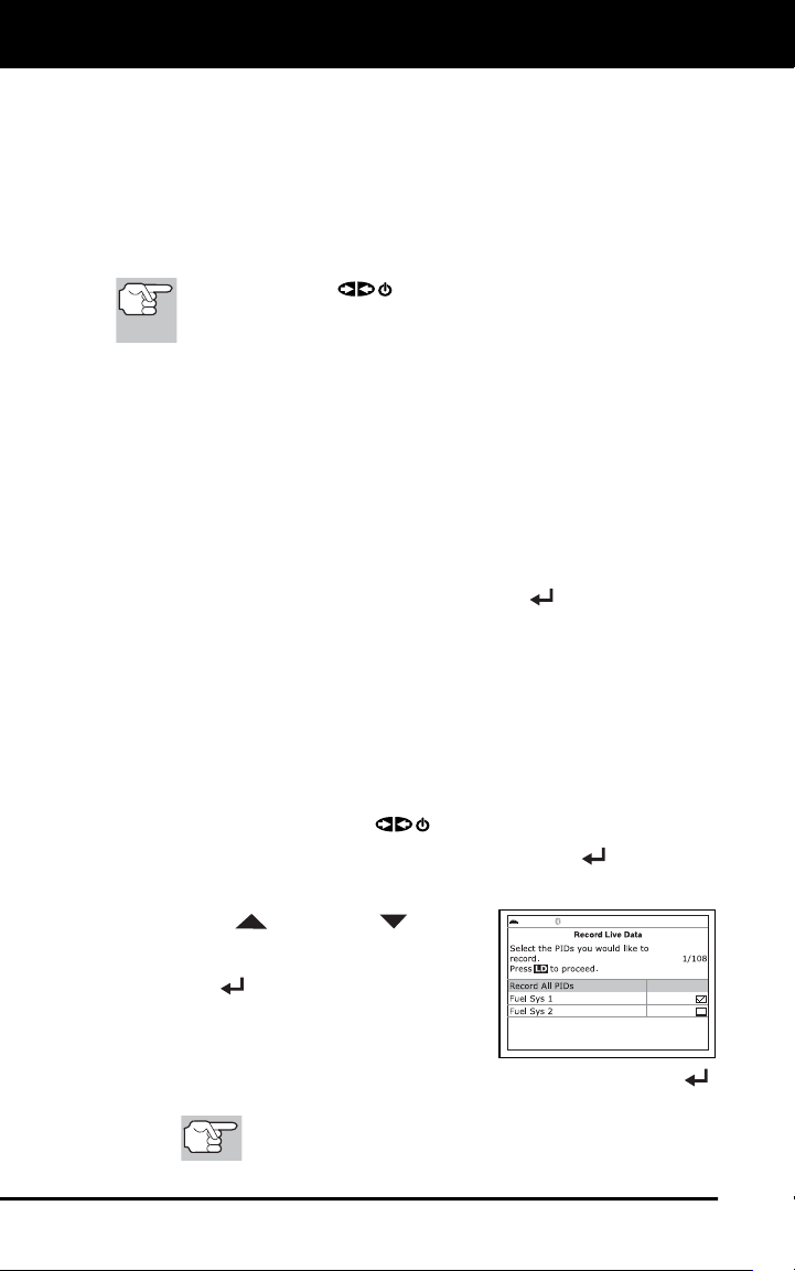
3. Select Record by DTC Trigger, then press ENTER
.
The Select PIDs to Record screen displays.
4. Press UP
and DOWN to scroll
through the available PIDs. When a PID
you wish to record is highlighted, press
ENTER
(a “checkmark” shows to
confirm your selection). Repeat until only
the PIDs you want to record have all been
selected.
To deselect a PID, highlight the PID, then press ENTER .
The checkmark is removed.
To record all PIDs, select Record All PIDs, the press
LD to continue.
Live Data Mode
RECORDING (CAPTURING) LIVE DATA
29
5. When you are finished making your selections, press LD to continue.
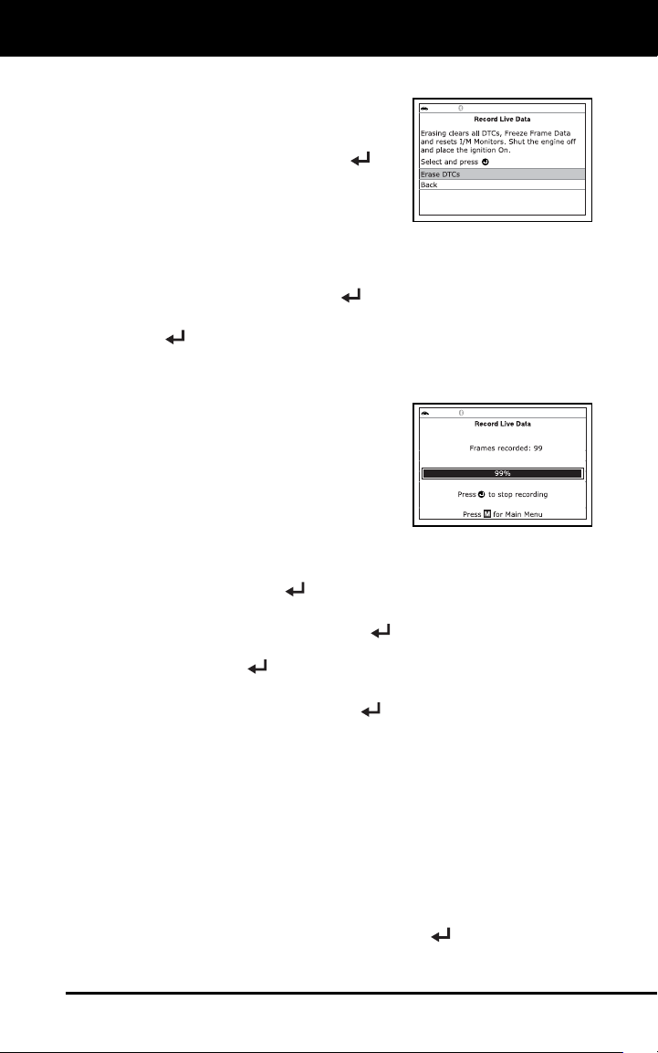
If DTCs are presently stored in the
vehicle’s computer, an advisory
message displays. Select Erase
DTCs, then press ENTER
. A
“One moment please…” message
displays while DTCs are erased
from the vehicle’s computer.
If the erase was not successful, an advisory message displays.
- To retry the erase process, verify that the Scan Tool is properly
connected to the vehicle’s DLC and that the ignition is on. Select
Erase, then press ENTER
.
- To exit the record function, select Back, then press ENTER
to return to the Record Live Data menu.
The Record Live Data screen displays.
6. Put the engine in the operating condition that causes the DTC to set.
If necessary, drive the vehicle until
you reach the vehicle speed at
which the problem occurs.
7. When the Scan Tool detects a fault that
causes a DTC to set, it automatically
records and saves approximately 100
frames of Live Data information in its
memory for each PID selected.
A progress message shows on the display.
- You can stop and save recorded Live Data at any time by
pressing ENTER
.
When recording is complete, a confirmation screen displays.
Select Yes and press ENTER
to playback Live Data (see
LIVE DATA PLAYBACK on page 31 for details) or select No and
press ENTER
to return to the Live Data menu, as desired.
If recording was not successful, an advisory message shows on
the display. Press the ENTER
button to return to the Record
Live Data menu.
Record by Manual Trigger
This option lets you select the precise time at which the Live Data recording
will occur. Record by Manual Trigger can be a very valuable tool when
troubleshooting intermittent problems that do not meet the requirements for
a DTC to set. The Scan Tool can record approximately 100 frames of Live
Data.
1. With the Scan Tool in Live Data mode (see VIEWING LIVE DATA
on page 25), press and hold LD until the Live Data Menu displays,
then release.
2. Select Record Live Data, then press ENTER
.
The Record Live Data Menu displays.
Live Data Mode
RECORDING (CAPTURING) LIVE DATA
30
If the Scan Tool fails to establish communication with the vehicle,
a “Communication Error” message displays.
- Ensure your vehicle is OBD2 compliant.
- Verify the connection at the DLC, and verify the ignition is ON.
- Turn the ignition OFF, wait 5 seconds, then back ON to reset
the computer.
- Press POWER/LINK
to continue.
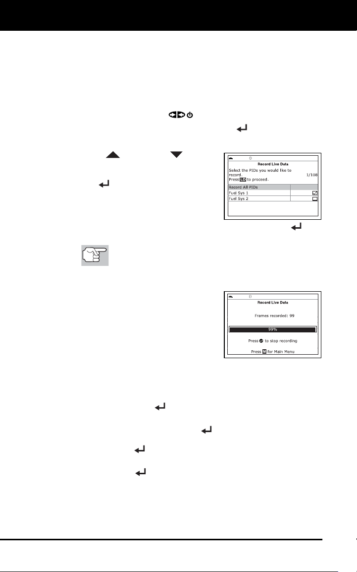
3. Select Record Manually, then press ENTER
.
The Select PIDs to Record screen displays.
4. Press UP
and DOWN to scroll
through the available PIDs. When a PID
you wish to record is highlighted, press
ENTER
(a “checkmark” shows to
confirm your selection). Repeat until
only the PIDs you want to record have
all been selected.
To deselect a PID, highlight the PID, then press ENTER . The
checkmark is removed.
To record all PIDs, select Record All PIDs, the press
LD to continue.
5. When you are finished making your selections, press LD to continue.
The Record Live Data screen
displays.
Highlight Start Recording. Put the
engine in the operating condition
where the problem manifests itself.
- If necessary, drive the vehicle
until you reach the vehicle speed
at which the problem occurs.
6. When the problem occurs, press and release LD.
A progress message shows on the display.
- You can stop and save recorded Live Data at any time by
pressing ENTER
.
When recording is complete, a confirmation screen displays.
Select Yes and press ENTER
to playback Live Data (see
LIVE DATA PLAYBACK on page 31 for details) or select No and
press ENTER
to return to the Live Data menu, as desired.
If recording was not successful, an advisory message displays.
Press ENTER
to return to the Record Live Data menu.
Live Data Mode
LIVE DATA PLAYBACK
31
LIVE DATA PLAYBACK
Once Live Data has been recorded, it is saved in the Scan Tool's
memory. You can view recorded Live Data immediately after recording
by selecting Yes from the Record Live Data confirmation screen (see
RECORDING (CAPTURING) LIVE DATA on page 28 for more
information), or you can view it later using the "Playback" function.
1. With the Scan Tool not connected to a vehicle, press the
POWER/LINK
button.
The "To Link" screen shows on the Scan Tool's display.
2. Press and hold the LD button until the Live Data Menu displays,
then release the LD button.
3. Select Playback Live Data, then press ENTER
.
The Playback Live Data menu displays.
When you select Yes from the Record Live Data confirmation
screen, the Scan Tool enters the "Live Data Playback" mode,
and the Playback Live Data menu displays.
4. Select Continuous Playback or Frame by Frame, as desired, then
press ENTER
.
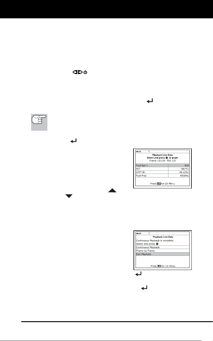
The display shows the recorded
Live Data, beginning with the
"trigger" frame.
Only a limited amount of PID data
can be displayed on the screen at
one time. If additional PID data is
available, a small arrow is shown on
the display. Press UP
and
DOWN
, as necessary, to view all available PID data.
When viewing recorded Live Data, look for any irregularities in any
of the PID values/signal information (LTFT %, RPM, MAP, TEMP,
etc.). If any PIDs are not within specification, or irregularities are
detected, follow the procedures in the vehicle's service repair
manual to perform additional troubleshooting and repair.
5. When you select Continuous
Playback, the Scan Tool plays
recorded data at a rate of one frame /
15 seconds. When playback is finished,
a Playback Complete message displays.
To play the data back again, select
Continuous Playback or Frame by
Frame, as desired, then press ENTER
.
To exit Live Data Playback mode and return to Live Data mode,
select Exit Playback, then press ENTER
.
6. When Frame by Frame is selected, you must scroll the individual
frames manually.

Live Data Mode
LIVE DATA PLAYBACK
32
When you have viewed all PID information for the current frame of
Live Data, select Next Frame or Previous Frame, as desired,
then press ENTER
.
To exit Live Data Playback mode, select Exit Playback, then
press ENTER
.
If there is no Live Data currently stored in the Scan Tool's
memory, an advisory message shows on the display. Press LD
to exit the "Live Data Playback" mode.
Additional Tests
SYSTEM CHECKS MENU
33
In addition to retrieving Diagnostic Trouble Codes (DTCs), you can use
the Scan Tool to perform additional diagnostic tests, to view diagnostic
and vehicle information stored in your vehicle's on-board computer, and
to configure the Scan Tool for your particular needs. Additional tests and
related functions are accessed through the Main Menu. The following
functions are available:
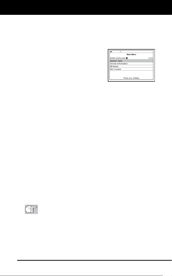
System Tests – Displays the System
Test menu, which lets your retrieve and
view results for the O2 Sensor Test and
OBD Monitor Test, and lets you initiate
a test of the vehicle’s EVAP system.
Service Reset – Lets you reset the Oil
Maintenance Light, reset the battery
monitor system after battery
replacement, perform calibration procedures for the vehicle’s
Steering Angle Sensor (SAS), perform Electronic Parking Brake
(EPB) cable replacement and reset, or perform Anti-Lock Brake
System (AVS) bleeding.
Service Check – Lets you view the current engine oil level and oil
life remaining.
Hybrid/EV Battery Test, Battery/Alternator Test – Performs a
check of the vehicle’s battery and alternator system (or hybrid/EV
battery system) to ensure the system is operating within acceptable
limits.
Drive Cycle Procedure – Lets you view drive cycle procedures for
a selected vehicle monitor.
DLC Locator – Lets you find the location of the Data Link
Connector (DLC) for a specified vehicle.
Vehicle Information – Displays the Vehicle Info menu, which lets
you retrieve and view reference information for the vehicle under
test.
Firmware Version – Displays the Scan Tool’s firmware version.
Tool Library – Displays the Tool Library menu, which provides
access to OBD1 and OBD2 DTC libraries and to definitions for
Monitor icons and LED indications.
Tool Settings – Displays the Tool Settings menu, which lets you
make several adjustments and settings to configure the Scan Tool
to your particular needs.
The System Tests and Vehicle Information options are
shown only when the Scan Tool is in Global OBD2 mode.
SYSTEM CHECKS MENU
Additional tests are accessed through the System Checks menu. The
following functions are available:
O2 Sensor Check - Retrieves and displays O2 sensor monitor test
results from your vehicle's on-board computer.
Additional Tests
SYSTEM CHECKS MENU
34
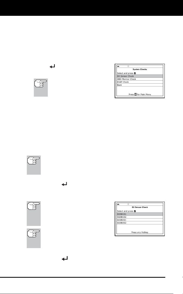
OBD Monitor Check - Retrieves and displays test results for
emission-related powertrain components and systems that are not
continuously monitored.
EVAP Check - Performs a leak test for the vehicle's EVAP system.
1. While linked to the vehicle, press M.
The Main Menu displays.
2. Select System Checks, then press
ENTER
.
The System Checks menu displays.
If System Checks is not
shown on the Main Menu, the
System Check functions are
not available for your vehicle.
O2 Sensor Check
OBD2 regulations require that applicable vehicles monitor and test operation
of the oxygen (O2) sensors to identify problems that can affect fuel
efficiency and vehicle emissions. These tests are performed automatically
when engine operating conditions are within predefined limits. Results of
these tests are stored in the on-board computer's memory.
The O2 Sensor Check function lets you retrieve and view O2 sensor
monitor test results for the most recently completed tests from your
vehicle's on-board computer.
The scan tool does not perform O2 sensor tests, but retrieves
results from the most recently performed O2 sensor tests from
the on-board computer's memory. You may retrieve O2 sensor
test results for only one test of one sensor at any given time.
1. From the System Checks menu, select O2 Sensor Check, then
press ENTER
.
2. A "One moment please..." message displays, followed by the select
sensor screen.
If O2 sensor check data is not
presently stored in the vehicle’s
computer, an advisory message
displays. Press M to return to the
Main Menu.
If O2 sensor checks are not
supported by the vehicle under
test, an advisory message displays. Press M to return to the
Main Menu.
3. Select the O2 sensor for which you wish to view test results, then
press ENTER
to display the test results.
Additional Tests
SYSTEM CHECKS MENU
35
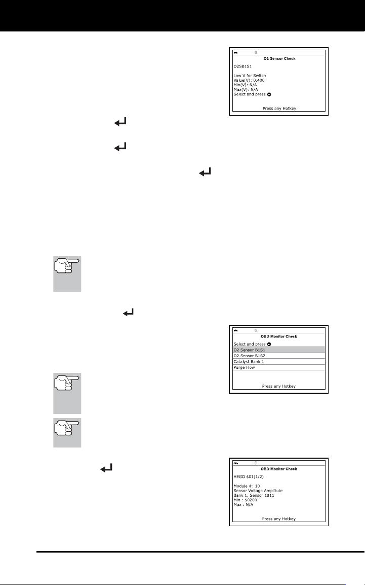
4. When test results have been retrieved,
data for the selected sensor test will
show on the Scan Tool's display.
5. When you have finished viewing the
retrieved test data:
To view test results for the next
sensor, select Next, then press
ENTER
.
To return to the Select Sensor screen, select Back, then press
ENTER
.
6. When you have finished viewing test data for all desired sensors,
select Back, then press ENTER
to return to the System Test
menu; or, press M to return to the Main Menu.
OBD Monitor Check
The OBD Monitor Check function retrieves and displays test results for
emission-related powertrain components and systems that are not
continuously monitored. The tests available are determined by the
vehicle manufacturer.
The Scan Tool does not perform the OBD monitor check, but
retrieves results from the most recently performed tests from
the on-board computer’s memory. You may retrieve OBD
monitor check results for only one test at any given time.
1. From the System Test menu, select OBD Monitor Check, then
press ENTER
.
2. A “One moment please. . .” message
displays, followed by the Select Test
screen. (Refer to the vehicle’s service
repair manual for information related to
non-continuous tests.)
If OBD monitor check data is not
presently stored in the vehicle’s
computer, an advisory message
displays. Press M to return to the Main Menu.
If OBD monitor checks are not supported by the vehicle under
test, an advisory message displays. Press M to return to the
Main Menu.
3. Select the desired test, then press
ENTER
to display the test results.
The display shows the following
information:
Test ID number
Module ID number
Component ID number
Additional Tests
PERFORMING SERVICE RESETS
36
Min or Max test limit (Only one test limit, either Min or Max, is
shown for any given test.)
Test Value and status
Status is calculated by the Scan Tool by comparing the Test
Value against the displayed test limit (either Min or Max).
Status is shown as either Low, High or OK.
4. When you have finished viewing the retrieved test data, select Back
on the Select Test screen, then press ENTER
to return to the
System Test menu; or, press M to return to the Main Menu.
EVAP Check
The EVAP Check function lets you initiate a leak test for the vehicle's
EVAP system.
The Scan Tool does not perform the leak test, but signals to
vehicle's on-board computer to initiate the test. The vehicle
manufacturer determines the criteria and method for stopping
the test once it has been started. BEFORE using the EVAP
Check function, refer to the vehicle's service repair manual to
determine the procedures necessary to stop the test.
1. From the System Test menu, select EVAP Check, then press
ENTER
.
2. A "One moment please..." message displays.
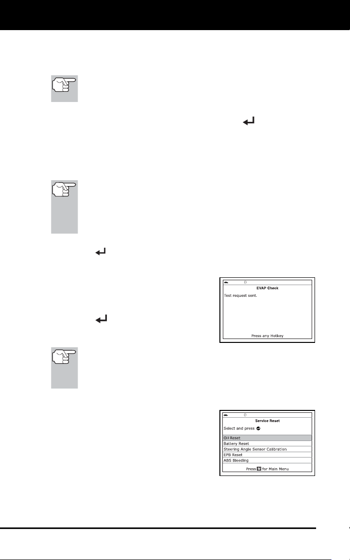
3. When the EVAP leak test has been
initiated by the vehicle's on-board
computer, a confirmation message
displays. Select Back, then press
ENTER
to return to the System Test
menu; or, press M to return to the Main
Menu.
Some vehicle manufacturers do not allow scan tools or other
external devices to control vehicle systems. If the EVAP Check is
not supported by the vehicle under test, an advisory message
displays. Press M to return to the Main Menu.
PERFORMING SERVICE RESETS
The Service Reset function offers up to five
options for performing service reset
procedures; Oil Reset, Battery Reset,
Steering Angle Sensor Calibration, EPB
Reset and ABS Bleeding.
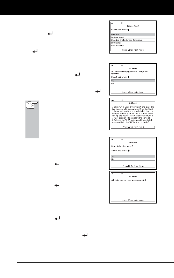
Resetting the Oil Maintenance Light
1. While linked to the vehicle, press M.
Additional Tests
PERFORMING SERVICE RESETS
37
The Main Menu displays.
2. Select Service Reset, then press
ENTER
to continue.
The Service Reset screen displays.
3. Select Oil Reset, then press ENTER
.
The Oil Reset screen displays.
If the vehicle under test is equipped
with a navigation system, select Yes,
then press ENTER
to continue.
If the vehicle under test is not
equipped with a navigation system,
select No, then press ENTER
to
continue.
If the Scan Tool cannot reset the
Oil Maintenance Light, an “instruc-
tional” dialog displays, showing
the manual procedures for reset-
ting the indicator light. When
finished viewing the instructions,
press M to return to the Main
Menu.
4. The Reset Oil Maintenance Indicator
screen displays.
If you do not wish to proceed with the
reset process, select No, then press
ENTER
to return to the System
Menu.
If you wish to proceed with the reset
process, select Yes, then press
ENTER
to continue.
5. When the reset process has completed,
a confirmation message displays. Press
M to return to the Main Menu.
If the oil reset was not successful, an advisory message displays.
To perform the oil reset by procedure, select Yes, then press
ENTER
. An “instructional” message displays, showing the
manual procedures for resetting the indicator light.
If you do not wish to perform the oil reset by procedure, select
No, then press ENTER
to return to the Main Menu.
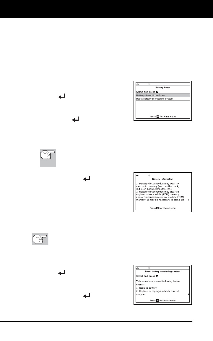
Additional Tests
PERFORMING SERVICE RESETS
38
Battery Reset
You can use the Scan Tool to view the procedures for resetting the
battery monitor system following battery replacement or perform battery
reset OBD service (for BMW, Ford and Volvo models only).
To view battery reset procedures:
1. While linked to a vehicle, press M.
The Main Menu displays.
2. Select Battery Reset, then press
ENTER
.
The Battery Reset menu displays.
3. Select Battery Reset Procedures, then
press ENTER
.
The Battery Reset Procedures menu displays. The menu
provides access to General Information, and procedures to be
followed Before Battery Disconnection, Before Battery
Connection, and After Battery Connection.
If battery reset procedures are not available for your
vehicle, an advisory message shows. Press M to return to
the Main Menu.
4. Select the procedure you wish to view,
then press ENTER
.
The selected procedure displays.
5. When you have finished viewing the
retrieved information, press M to return
to the Main Menu. Repeat steps 2
through 4 to view additional procedures.
To perform battery reset OBD service:
The Battery Reset OBD Service option is available for BMW,
Ford and Volvo vehicles only.
1. While linked to a vehicle, press M.
The Main Menu displays.
2. Select Battery Reset, then press
ENTER
.
The Battery Reset menu displays.
3. Select Battery Reset OBD Service,
then press ENTER
.
An “instructional” message displays.
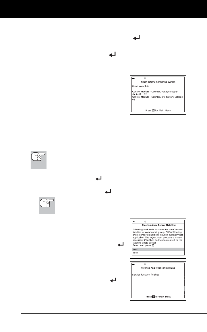
Additional Tests
PERFORMING SERVICE RESETS
39
4. Follow the instructions provided to prepare the vehicle for battery
reset OBD service. When all necessary procedures have been
performed, select Next, then press ENTER
.
A “Live Data” screen displays, if applicable.
5. Select Next, then press ENTER
.
A “One moment please…” message displays while battery reset
is in process.
6. If the battery reset process is successful,
a “Reset Complete” message displays.
Press M to return to the Main Menu.
If the battery reset process is not
successful, a “Reset Fail” message
displays. Press M to return to the
Main Menu.
Steering Angle Sensor (SAS) Calibration
The Steering Angle Sensor Calibration function is available for BMW,
Chrysler, Ford, GM, Hyundai, Nissan, Toyota, Volkswagen and Volvo
vehicles only. Calibration procedures vary between vehicle makes and
models.
If an error occurs while performing calibration procedures, an
“advisory” message displays. Press M to return to the Main
Menu.
1. Select Steering Angle Sensor Calibration in the Service Reset
menu, then press ENTER
.
For some vehicles, a submenu displays. Select the desired
option, then press ENTER
. Proceed to step 2.
If SAS calibration is not supported by the vehicle under
test, an “advisory” message displays. Press M to return to
the Main Menu.
2. A “One moment” message displays,
followed by one or more “informational/
instructional” screens.
Perform test procedures as directed.
Select Next and press ENTER
,
as appropriate, to scroll to the next
screen.
3. For some vehicles, “status” screens
display as each phase of the calibration
procedure is successfully completed.
Select Next and press ENTER
, as
appropriate, to scroll to the next screen.
A “results” screen displays when the
calibration procedure has completed.
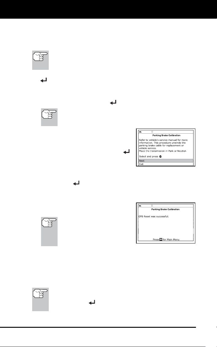
Additional Tests
PERFORMING SERVICE RESETS
40
4. Press M to return to the Main Menu.
EPB Reset
EPB Reset procedures vary between vehicle makes and models.
If an error occurs while performing calibration procedures, an
“advisory” message displays. Press M to return to the Main
Menu.
1. Select EPB Reset in the Service Reset menu, then press ENTER
.
A “One moment” message displays.
For some vehicles, a submenu displays. Select the desired
option, then press ENTER
. Proceed to step 2.
If EPB reset is not supported by the vehicle under test, an
“advisory” message displays. Press M to return to the
Main Menu.
2. One or more “informational/ instructional”
screens display.
Perform test procedures as directed.
Select Next and press ENTER
,
as appropriate, to scroll to the next
screen.
3. For some vehicles, “status” screens display as each phase of the
calibration procedure is successfully completed. Select Next and
press ENTER
, as appropriate, to scroll to the next screen.
A “One moment” message displays while the procedure is in
process.
A “results” screen displays when the
calibration procedure has completed.
If the procedure is stopped
due to a communication error,
an “advisory” message
displays. Press M to return to
the Main Menu.
4. Press M to return to the Main Menu.
ABS Bleeding
The ABS Bleeding function is available for Chrysler, GM, Hyundai/Kia,
Mazda and Toyota vehicles only. Procedures vary between vehicle
makes and models.
If an error occurs while performing ABS bleeding procedures,
an “advisory” message displays. Select Exit or Back and
press ENTER
, as necessary, to return to the Service
Reset menu.
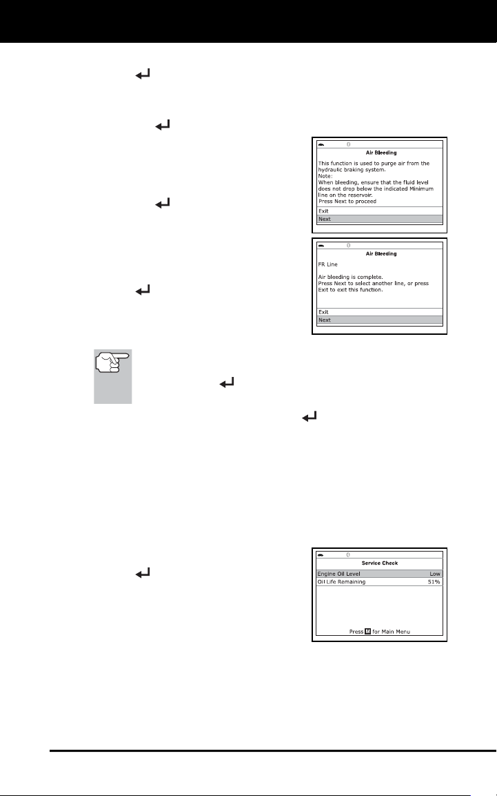
Additional Tests
PERFORMING A SERVICE CHECK
41
1. Select ABS Bleeding in the Service Reset menu, then press
ENTER
.
A “One moment” message may display.
A submenu displays. Select the desired option, then press
ENTER
. Proceed to step 2.
2. One or more “informational/ instructional”
screens display.
Perform test procedures as directed.
Select Next or Continue and press
ENTER
, as appropriate, to scroll
to the next screen.
3. For some vehicles, “status” screens
display as each phase of the calibration
procedure is successfully completed.
Select Next or Continue and press
ENTER
, as appropriate, to scroll to
the next screen.
A “results” screen displays when the
procedure has completed.
If the procedure is stopped due to a communication error,
an “advisory” message displays. Select Exit or Back and
press ENTER
, as necessary, to return to the Service
Reset menu.
4. Select Exit or Back and press ENTER
, as necessary, to return
to the Service Reset menu.
PERFORMING A SERVICE CHECK
The Service Check function lets you check the current oil level and oil
life.
1. While linked to the vehicle, press M.
The Main Menu displays.
2. Select Service Check, then press
ENTER
.
The Service Check screen displays.
The screen shows the current
Engine Oil Level and Oil Life
Remaining.
3. When you have finished viewing the information, press M to return
to the Main Menu.
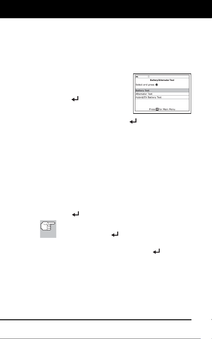
Additional Tests
BATTERY/ALTERNATOR TEST
42
BATTERY/ALTERNATOR TEST
The Scan Tool can perform a check of the vehicle’s battery and
alternator system to ensure the system is operating within acceptable
limits. You can perform a battery check only, or an alternator system
(battery and alternator) check.
To perform a battery check ONLY:
1. Press M and release.
The Main Menu displays.
2. Select Battery/Alternator Test, then
press ENTER
.
The Battery/Alternator Test Menu
displays.
3. Select Battery Test, then press ENTER
.
An “instructional” message displays, showing the procedures to
prepare the vehicle for the battery check.
4. Prepare the vehicle for the battery check:
Turn the engine off.
Place the transmission in PARK or NEUTRAL, and set the
parking brake.
Make a visual check of the battery’s condition. If the battery
terminals are corroded or other damage is present, clean or
replace the battery as appropriate.
For “unsealed” batteries, make sure the water level in each cell
is above the battery plates.
Turn the ignition on. DO NOT start the engine.
5. Press ENTER
to begin the battery check.
If the engine is running, an advisory message shows. Turn
the engine off, then turn the ignition on. DO NOT start the
engine. Press ENTER
to continue.
An “instructional” message shows.
6. Turn the vehicle’s headlights on, the press ENTER
to continue.
A “countdown” message shows on the Scan Tool’s display while
the battery check is in process.
If battery voltage is less than 12.1 volts, an advisory message
shows. Press M to return to the Main Menu. Turn the ignition off
and disconnect the Scan Tool from the vehicle. Fully charge the
battery, then repeat the battery check.
If battery voltage is greater than 12.1 volts, an “instructional”
message shows.
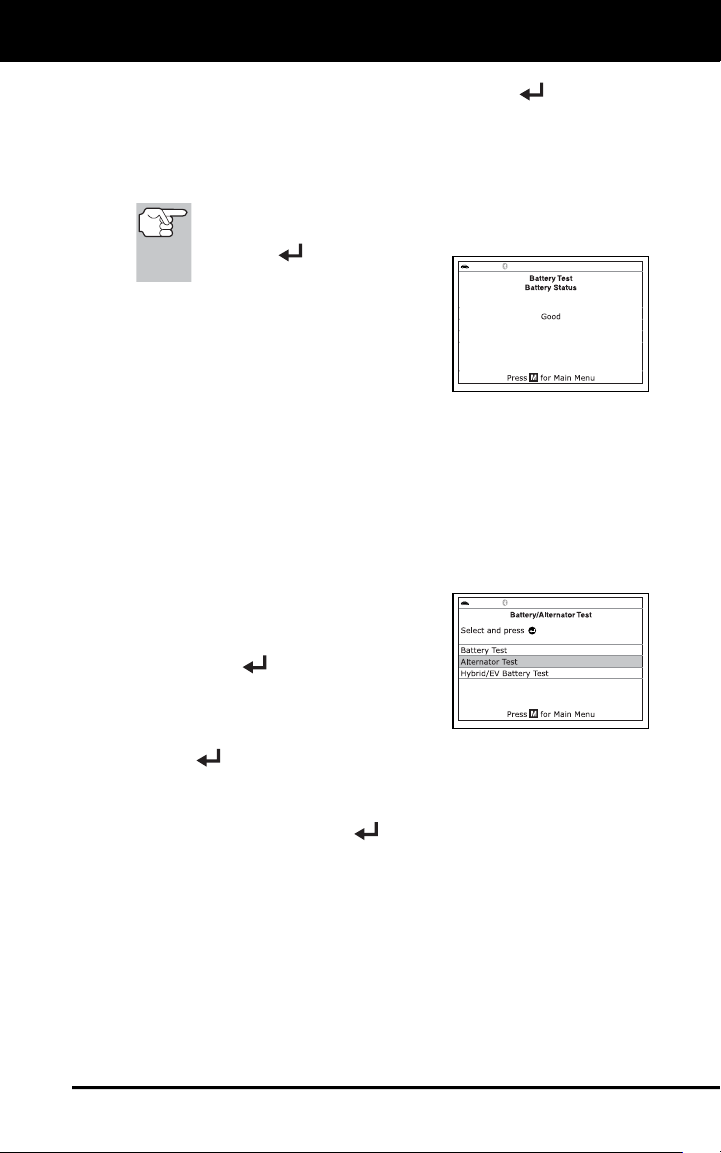
Additional Tests
BATTERY/ALTERNATOR TEST
43
7. Turn the vehicle’s headlights off, the press ENTER to continue.
An “instructional” message shows.
8. Start the vehicle’s engine. Allow the engine to run for several
seconds, then turn the engine off. Repeat for a total of three
“start/stop” cycles.
If the Scan Tool did not detect “cranking status” for the
vehicle’s engine, an advisory message shows. Press
ENTER
to repeat the
battery check, or, press M to
return to the Main Menu.
9. When the battery check is complete, a
results screen displays the battery
status. The System Status LEDs
provide a PASS/FAIL indication, as
follows:
Green = Good
Yellow = Normal
Red = Warning/Bad
10. Press M to return to the Main Menu.
To perform a charging system check:
1. Press M and release.
The Main Menu displays.
2. Select Battery/Alternator Test, then
press ENTER
.
The Battery/Alternator Test Menu
displays.
3. Select Alternator Test, then press
ENTER
.
An “instructional” message shows.
4. Start and warm the engine to normal operating temperature. Turn on
the headlights. Press ENTER
to continue.
An “instructional” message shows.
5. Press the accelerator pedal to raise engine speed to 2000 RPM,
and maintain the engine speed.
When engine speed is within the required range, the alternator
test begins. A progress screen shows.
When the “countdown” timer expires, an “instructional” message
shows.
6. Turn the vehicle’s headlights off, and return the engine to idle speed.
A “One moment please…” message displays while the test
results are retrieved.
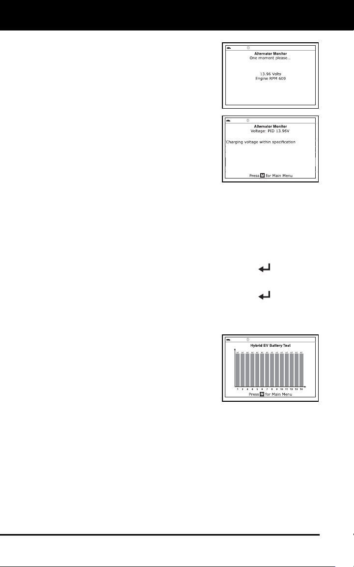
Additional Tests
VIEWING DRIVE CYCLE PROCEDURES
44
7. When the alternator check is complete,
a results screen shows charging system
voltage and indicates whether or not the
charging system is within acceptable
limits. The System Status LEDs provide
a PASS/FAIL indication, as follows:
Green = System within limits
Yellow = Over charging or under
charging
Red = Excessive over charging or
under charging
If the alternator voltage is less than
9 V, the red, yellow and green
SYSTEM STATUS LEDs will flash
on and off.
8. Press M to return to the Main Menu.
To perform a hybrid/EV battery system check:
1. Press M and release.
The Main Menu displays.
2. Select Battery/Alternator Test, then press ENTER
.
The Battery/Alternator Test Menu displays.
3. Select Hybrid/EV Battery Test, then press ENTER
.
If the vehicle supports battery Live Data, the Battery Live Data
screen displays. The screen shows the state of charge, battery
pack voltage and sum of cell voltages for the battery pack.
If the vehicle supports battery cell
display, a graphic display of the
current state of charge for all cells in
the battery pack displays.
4. When you have finished viewing the
retrieved information, press M to return
to the Main Menu.
VIEWING DRIVE CYCLE PROCEDURES
A Drive Cycle for a Monitor requires that the vehicle is driven in such a
way that all the required “Enabling Criteria” for the Monitor to run and
complete its diagnostic testing are met. You can use the Scan Tool to
view the Drive Cycle procedures for a selected Monitor.
1. While linked to a vehicle, press M.
The Main Menu displays.
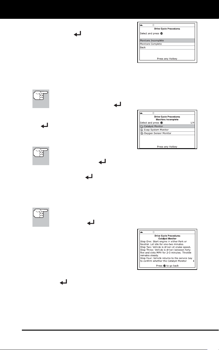
Additional Tests
VIEWING DRIVE CYCLE PROCEDURES
45
2. Select Drive Cycle Procedures, then
press ENTER
.
A “One moment please…” message
displays while the Scan Tool
retrieves Monitor status from the
vehicle’s computer.
3. When Monitor status has been retrieved, the Drive Cycle
Procedures menu displays. Depending on Monitor status, you can
view Drive Cycle procedures for Monitors Incomplete or Monitors
Complete.
If Drive Cycle Procedures are not available for the vehicle, an
advisory message shows on the Scan Tool’s display. Select
Back, then press ENTER
to return to the Main Menu.
4. Select Monitors Incomplete or Monitors
Complete, as desired, then press ENTER
.
A list of the available Monitors for
the selected status displays.
If no Monitors for the selected
status are detected, an advisory message shows. Select Back,
then press ENTER
to return to the Main Menu.
5. Select the Monitor for which you wish to view Trip Cycle Procedures,
then press ENTER
.
A “One moment please…” message displays while the Scan
Tool retrieves the requested Trip Cycle Procedure. The Trip
Cycle Procedures screen for the Monitor displays when the
procedure has been retrieved.
If a Trip Cycle Procedure for the selected Monitor is not
available, an advisory message shows. Select Back, then
press ENTER
to return to the Main Menu.
6. The Drive Cycle Procedure screen
shows the specific set of operating
procedures that ensure the vehicle is
driven in such a way that all the
required “Enabling Criteria” for the
Monitor to run and complete its
diagnostic testing are met.
7. When you are finished viewing the Drive Cycle Procedures, press
ENTER
to return to the Drive Cycle Procedures menu, or, press
M to return to the Main Menu.
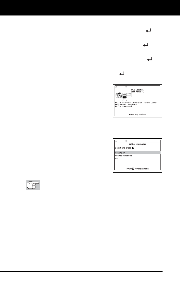
Additional Tests
USING THE DLC LOCATOR - VIEWING VEHICLE INFORMATION
46
USING THE DLC LOCATOR
1. Select DLC Locator in the Main Menu, then press ENTER .
The Select Vehicle Model Year screen displays.
2. Select the desired vehicle model year, then press ENTER
.
The Select Vehicle Manufacturer screen displays.
3. Select the desired vehicle manufacturer, then press ENTER
.
The Select Vehicle Model screen displays.
4. Select the desired model, then press ENTER
.
The DLC Location screen for the
selected vehicle displays.
The DLC Location screen shows the
selected vehicle make and model, a
description of the DLC location and
whether the DLC is “covered” or
“uncovered,” and includes a picture
of the DLC location.
5. When you have finished viewing the DLC location, press any hotkey
to exit the DLC Locator.
VIEWING VEHICLE INFORMATION
The Vehicle Information function offers
three options for retrieving reference
information for the vehicle under test;
Vehicle ID, Available Modules and IPT
(In-Use Performance Tracking).
Retrieving Vehicle ID Information
The Vehicle ID function is applicable to model year 2000 and
newer OBD2-compliant vehicles.
The Scan Tool can retrieve a list of information (provided by the vehicle
manufacturer), unique to the vehicle under test, from the vehicle's on-
board computer. This information may include:
The vehicle's VIN number
The control module identification number
The vehicle's calibration ID(s). These IDs uniquely identify the
software version(s) for the vehicle's control module(s).
The Vehicle's Calibration Verification Number(s) (CVNs) required by
ODB2 regulations. CVNs are used to determine if emission-related
calibrations for the vehicle under test have been changed. One or
more CVNs may be returned by the vehicle's computer.
1. With the Scan Tool in OBD2 mode, press M.
The Main Menu displays.
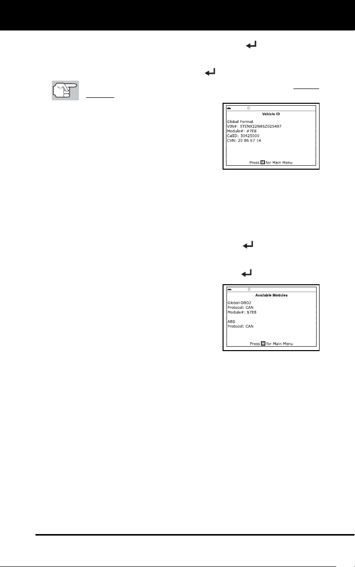
Additional Tests
VIEWING VEHICLE INFORMATION
47
2. Select Vehicle Information, then press ENTER .
The Vehicle Information menu displays.
3. Select Vehicle ID, then press ENTER
.
The first time the Vehicle ID function is used, it may take several
minutes to retrieve the information from the vehicle's computer.
4. When the retrieval process is completed,
the vehicle ID information displays.
5. When you have finished viewing the
retrieved vehicle ID information, press
the M
button to return to the Main Menu.
Viewing Available Modules
The Scan Tool can retrieve a list of modules supported by the vehicle
under test.
1. With the Scan Tool in OBD2 mode, press and release M.
The Main Menu displays.
2. Select Vehicle Information, then press ENTER
.
The Vehicle Information menu displays.
3. Select Available Modules, then press ENTER
.
4. When the retrieval process is completed,
a complete list of modules supported by
the vehicle under test displays.
5. When you have finished viewing the list
of available modules, press M to return
to the Main Menu.
Viewing In-use Performance Tracking
(IPT)
The Scan Tool can retrieve In-use Performance Tracking (IPT) statistics
for monitors supported by the vehicle under test. Two values are
returned for each monitor; the number of times that all conditions
necessary for a specific monitor to detect a malfunction have been
encountered (XXXCOND), and the number of times that the vehicle has
been operated under the specific conditions for the monitor (XXXCOMP).
Statistics are also provided for the number of times the vehicle has been
operated in OBD monitoring conditions (OBDCOND), and the number of
times the vehicle’s engine has been started (IGNCNTR).
1. With the Scan Tool in OBD2 mode, press and release M.
The Main Menu displays.
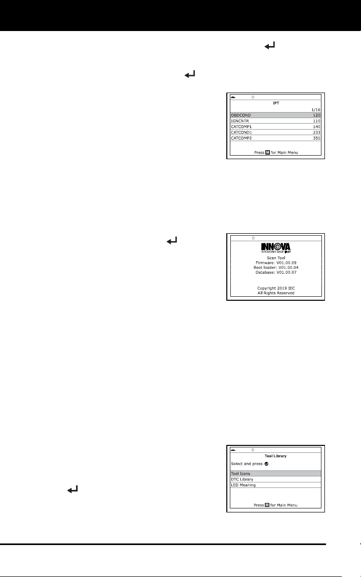
Additional Tests
VIEWING THE FIRMWARE VERSION - THE TOOL LIBRARY
48
2. Select Vehicle Information, then press the ENTER
button.
The Vehicle Information menu displays.
3. Select IPT, then press ENTER
.
4. When the retrieval process is completed,
the In-use Performance Tracking
statistics for the vehicle under test
display.
If In-use Performance Tracking is
not available for your vehicle, an
advisory message shows on the
Scan Tool’s display. Press M to
return to the Main Menu.
5. When you have finished viewing the statistics, press M to return to
the Main Menu.
VIEWING THE FIRMWARE VERSION
1. Select Firmware Version in the Main
Menu, then press ENTER
.
The Firmware Version screen dis-
plays for four seconds.
The screen shows the Scan Tool’s
current firmware version, bootloader
version and database version.
2. The display returns to the Main Menu.
THE TOOL LIBRARY
The Tool Library contains valuable reference information for the Scan
Tool. The following functions are available:
Tool Icons – Shows the full names for the I/MMONITOR STATUS
icons shown and descriptions of informational icons on the Scan
Tool’s display.
DTC Library – Provides access to libraries of OBD1 and OBD2
DTC definitions.
LED Meaning – Provides descriptions of the meaning of the Scan
Tool SYSTEM STATUS LEDs.
1. While linked to the vehicle, press M.
The Main Menu displays.
2. Select Tool Library, then press ENTER
.
The Tool Library menu displays.
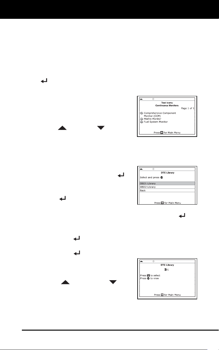
Additional Tests
THE TOOL LIBRARY
49
Viewing Tool Icon Descriptions
The I/M MONITOR STATUS icons on the Scan Tool’s LCD display
provide an indication of the “Completed / Not Complete” status for all I/M
Monitors supported by the vehicle under test. The Tool Icons function
displays the full name for each Monitor icon, as well as descriptions of
the meanings of other informational icons shown on the Scan Tool’s
display.
1. From the Tool Library menu, select Tool Icons, then press ENTER
.
The Tool Icons screen displays.
The screen shows a list of the 15
Monitor icons, along with the full
name for each icon, as well as
descriptions of the meanings of
other informational icons. Use the
UP
and DOWN buttons, as
necessary, to scroll the list.
2. When you have finished viewing the tool icon descriptions, press M
to return to the Main Menu.
Using the DTC Library (OBD1)
1. From the Tool Library menu, select
DTC Library, then press ENTER
.
The Select Library screen displays.
2. Select OBD1 Library, then press
ENTER
.
The Select Manufacturer screen displays.
3. Select the desired vehicle manufacturer, then press ENTER
.
A confirmation message shows.
- If the correct manufacturer is not shown, select No, then press
ENTER
to return to the list of vehicle manufacturers.
- If the correct manufacturer is shown, select Yes, then press
ENTER
.
4. The Enter DTC screen displays.
The screen shows the code “001,”
with the first “0” highlighted. Press
UP
and DOWN , as
necessary, to scroll to the first digit
of the DTC, then press DTC/FF.
The selected character displays solid, and the next character is
highlighted.
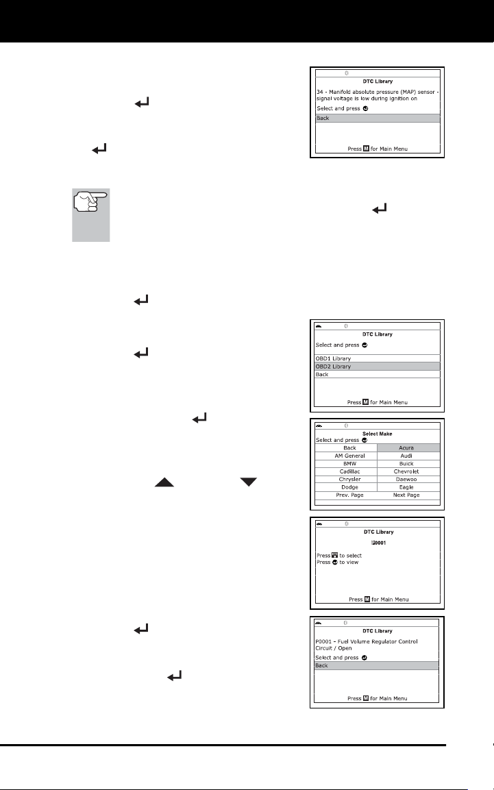
Additional Tests
THE TOOL LIBRARY
50
5. Select the remaining digits in the DTC
in the same way. When you have
selected all the DTC digits, press
ENTER
to view the DTC definition.
6. When you have finished viewing the DTC
definition, select Back, then press ENTER
to return to the Enter DTC screen and
enter additional DTCs; or, press M
to
return to the Main Menu.
If a definition for the DTC you entered is not available, an advisory
message shows. Select Back, then press ENTER
to return to
the Enter DTC screen and enter additional DTCs; or, press M
to
return to the Main Menu.
Using the DTC Library (OBD2)
1. From the Tool Library menu, select DTC Library, then press
ENTER
.
The Select Library screen displays.
2. Select OBD2 Library, then press
ENTER
.
The Select Manufacturer screen
displays.
3. Select the desired vehicle manufacturer,
then press ENTER
.
The Enter DTC screen displays.
The screen shows the code
“P0001,” with the “P” highlighted.
4. Use the UP
and DOWN buttons,
as necessary, to scroll to the desired
DTC type (P=Powertrain, U=Network,
B=Body, C=Chassis), then press
DTC/FF.
The selected character displays solid,
and the next character is highlighted.
5. Select the remaining digits in the DTC
in the same way. When you have
selected all the DTC digits, press
ENTER
to view the DTC definition.
6. When you have finished viewing the
DTC definition, highlight Back, then
press ENTER
to return to the Enter
DTC screen and enter additional DTCs;
or, press M
to return to the Main Menu.
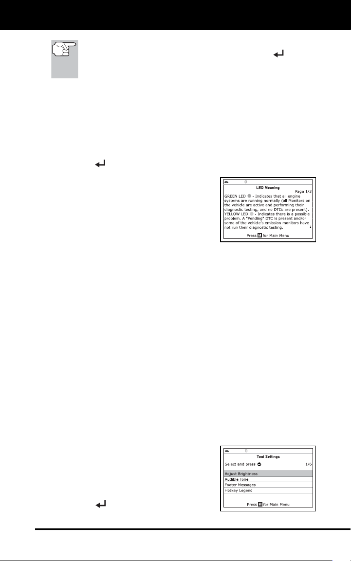
Additional Tests
ADJUSTMENTS AND SETTINGS
51
If a definition for the DTC you entered is not available, an advisory
message shows. Highlight Back, then press ENTER
to return
to the Enter DTC screen and enter additional DTCs; or, press M
to
return to the Main Menu.
Viewing LED Meanings
The SYSTEM STATUS LEDs on the Scan Tool provide a visual
indication of the I/M Readiness status of the vehicle under test. The
LED Meanings function provides a description of the meanings of the
green, yellow and red SYSTEM STATUS LEDs.
1. From the Tool Library menu, select LED Meaning, then press
ENTER
.
The LED Meaning screen displays.
The screen provides a description of
the meanings of the green, yellow
and red SYSTEM STATUS LEDs.
2. When you have finished viewing the
LED meanings, press M
to return to the
Main Menu.
ADJUSTMENTS AND SETTINGS
The Scan Tool lets you make several adjustments and settings to
configure the Scan Tool to your particular needs. The following
adjustments and settings are available.
Adjust Brightness: Adjusts the brightness of the display screen.
Audible Tone: Turns the Scan Tool’s audible tone “on” and “off.”
When turned “on,” a tone sounds each time a button is pressed.
Footer Messages: Turns the navigational “footers” at the bottom of
most display screens “on” and “off.”
Hotkey Legend: Shows functional descriptions for the Scan Tool’s
hotkeys.
Language Selection: Sets the display language for the Scan Tool
to English, French or Spanish.
Unit of Measurement: Sets the Unit of Measurement for the Scan
Tool’s display to USA or metric.
To enter the Tool Settings mode:
1. While linked to the vehicle, press and
release the M button.
The Main Menu displays.
2. Select Tool Settings, then press
ENTER
.
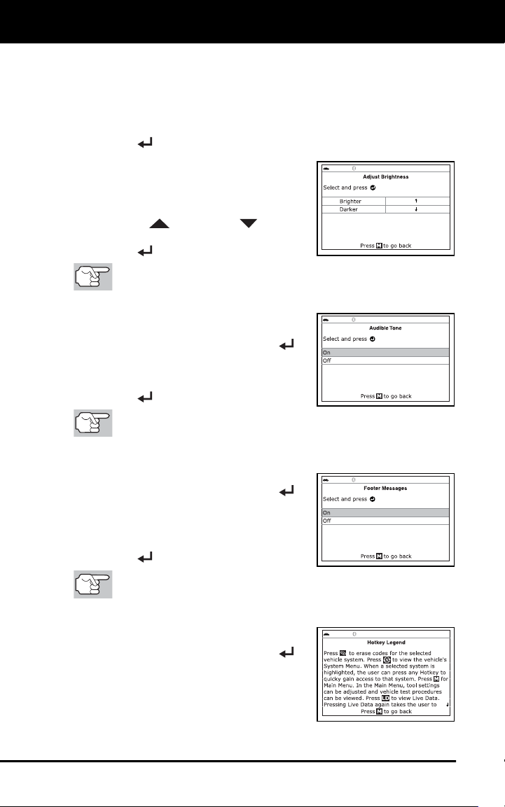
Additional Tests
ADJUSTMENTS AND SETTINGS
52
The Tool Setting menu displays.
3. Make adjustments and settings as follows.
Adjusting Display Brightness
1. Select Adjust Brightness in the Tool Settings menu, then press
ENTER
.
The Adjust Brightness screen displays.
The Adjust Brightness field shows
the current brightness setting, from 1
to 5.
2. Press UP
and DOWN
to make
the display lighter or darker, then press
ENTER
to save your changes.
To return to the Tool Settings menu without making changes,
press M.
Enabling/Disabling the Audible Tone
1. Select Audible Tone in the Tool
Settings menu, then press ENTER
.
The Audible Tone screen displays.
2. Select On or Off as desired, then press
ENTER
to save your changes.
To return to the Tool Settings menu without making changes,
press M.
Enabling/Disabling Navigational Footers
1. Select Footer Messages in the Tool
Settings menu, then press ENTER
.
The Footer Messages screen
displays.
2. Select On of Off as desired, then press
ENTER
to save your changes.
To return to the Tool Settings menu without making changes,
press M.
Viewing the Hotkey Legend
1. Select Hotkey Legend in the Tool
Settings menu, then press ENTER
.
The Hotkey Legend screen displays.
The screen shows a functional
description of each of the Scan
Tool’s hotkeys.
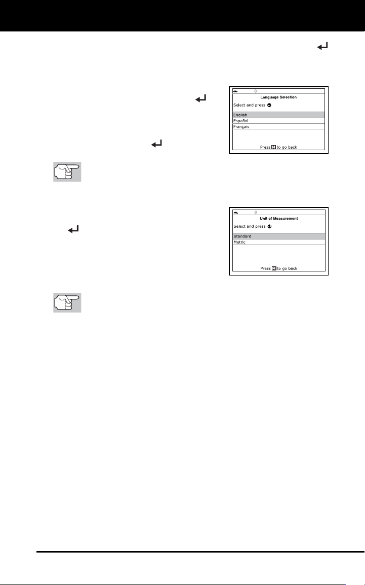
Additional Tests
ADJUSTMENTS AND SETTINGS
53
2. When you have finished viewing the Hotkey Legend, press ENTER
to return to the Tool Settings menu.
Selecting the Display Language
1. Select Language Selection in the Tool
Settings menu, then press ENTER
.
The Language Selection screen dis-
plays.
2. Select the desired display language,
then press ENTER
to save your
changes.
To return to the Tool Settings menu without making changes,
press M.
Setting the Unit of Measurement
1. Select Unit of Measurement in the
Tool Settings menu, then press ENTER
.
The Unit of Measurement screen
displays.
2. Select the desired unit of measurement,
then choose Save to save your
changes.
To return to the Tool Settings menu without making changes,
press M.
Exiting the MENU Mode
Press M to return to the Main Menu.
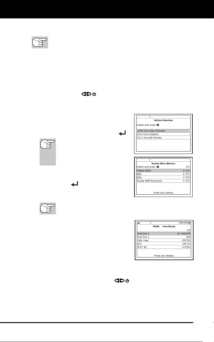
Using Scan Tool Memory
VIEWING DATA IN MEMORY
54
When you retrieve DTCs from a vehicle, the data is saved to the Scan
Tool’s memory.
Each time you retrieve DTCs, existing data in the Scan Tool's
memory is overwritten with the new data.
VIEWING DATA IN MEMORY
When you turn the Scan Tool on while NOT connected to a vehicle, and
data is currently saved in the Scan Tool’s memory, the Scan Tool enters
Memory mode. You can view DTCs and Live Data stored in the Scan
Tool’s memory.
1. With the Scan Tool NOT connected to a vehicle, press and release
the POWER/LINK
button to turn the Scan Tool on.
If the Scan Tool’s batteries are low, a warning message displays.
Replace the batteries before continuing.
2. If more than one vehicle is stored in the
Scan Tool’s memory, the Vehicle
Selection menu displays. Select the
desired vehicle, then press ENTER
.
If there are no vehicles
currently stored in the Scan
Tool, an advisory message
displays. Press M to return to
the Main Menu.
The Memory System Menu displays.
3. Select the DTCs you wish to view, then
press ENTER
.
The Scan Tool displays the "priority"
DTC.
If there are no DTCs currently stored in the Scan Tool’s
memory, an advisory message shows.
Press DTC/FF
to scroll through all
stored DTCs, and to view Freeze
Frame data for the priority DTC.
When all DTCs have been displayed
and DTC/FF
is pressed, the Scan
Tool displays the first enhanced DTC
stored in memory. Press DTC/FF
to
scroll through all stored enhanced
DTCs.
4. When you have finished viewing data in the Scan Tool's memory,
press and release POWER/LINK
to turn the Scan Tool off.

Notes
55

Notes
56

Warranty and Servicing
57
LIMITED ONE YEAR WARRANTY
The Manufacturer warrants to the original purchaser that this unit is free
of defects in materials and workmanship under normal use and
maintenance for a period of one (1) year from the date of original
purchase.
If the unit fails within the one (1) year period, it will be repaired or
replaced, at the Manufacturer’s option, at no charge, when returned
prepaid to the Service Center with Proof of Purchase. The sales receipt
may be used for this purpose. Installation labor is not covered under this
warranty. All replacement parts, whether new or remanufactured,
assume as their warranty period only the remaining time of this warranty.
This warranty does not apply to damage caused by improper use,
accident, abuse, improper voltage, service, fire, flood, lightning, or other
acts of God, or if the product was altered or repaired by anyone other
than the Manufacturer’s Service Center.
The Manufacturer, under no circumstances shall be liable for any
consequential damages for breach of any written warranty of this unit.
This warranty gives you specific legal rights, and you may also have
rights, which vary from state to state. This manual is copyrighted with all
rights reserved. No portion of this document may be copied or
reproduced by any means without the express written permission of the
Manufacturer. THIS WARRANTY IS NOT TRANSFERABLE. For
service, send via U.P.S. (if possible) prepaid to Manufacturer. Allow 3-4
weeks for service/repair.
SERVICE PROCEDURES
If you have any questions, require technical support or information on
UPDATES and OPTIONAL ACCESSORIES, please contact your local
store, distributor or the Service Center.
USA & Canada:
(800) 544-4124 (6:00 AM-6:00 PM PST, Monday through Saturday)
All others: (714) 241-6802 (6:00 AM-6:00 PM PST, Monday through
Saturday)
FAX: (714) 241-3979 (24 hr.)
Web: www.innova.com