Loading ...
Loading ...
Loading ...
8
Installation Instructions
4. COLD WATER PIPE GROUNDING
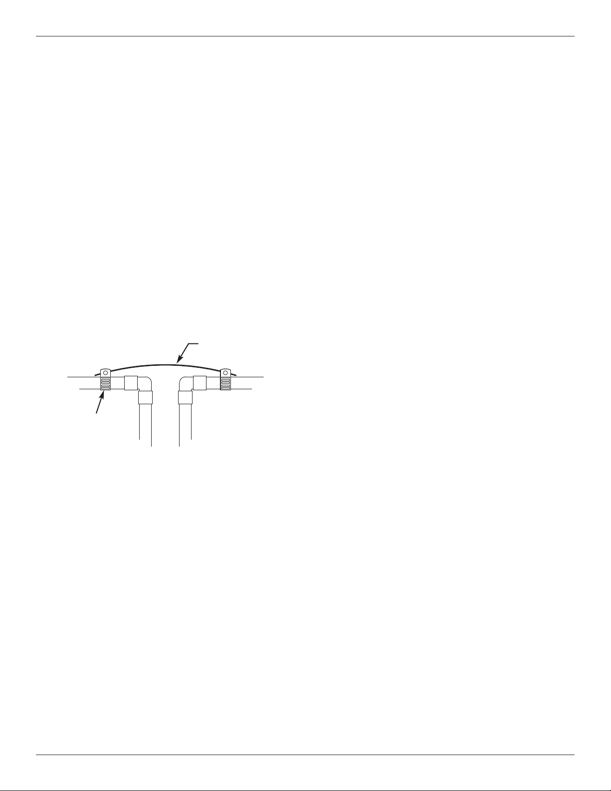
CAUTION: The house cold water pipe (metal only) is
often used as a ground for the house elec-
trical system, The 3-valve bypass type of
installation, shown in Figure 3, will maintain
ground continuity. If you use a plastic
bypass valve at the unit, continuity is bro-
ken. To restore the ground, do the follow-
ing:
a. Install a #4 copper wire across the removed section
of main water pipe, securely clamping it at both
ends (See Figure 9) - parts not included.
NOTE: Check local plumbing and electrical codes for
proper installation of grounding. The installa-
tion must conform to them. In Massachusetts,
plumbing codes of Massachusetts shall be
conformed to. Consult with your licensed
plumber.
5. INSTALL VALVE DRAIN HOSE
a. Take a length of 5/8” inside diameter garden hose
and attach to the valve drain fitting (See Figure 4 on
page 6).
b. Locate the other end of the hose at a suitable drain
point (floor drain, sump, laundry tub, etc.). Check
and comply with local codes. Refer to Figure 4 on
page 6 if codes require a rigid pipe drain run.
IMPORTANT: Use high quality, thick wall hose that will
not easily kink or collapse. The filter will
not backwash properly if water cannot
exit this hose during recharges.
c. Tie or wire the hose in place at the drain point.
Water pressure will cause it to whip during the back-
wash and fast rinse cycles of recharge. Also pro-
vide an air gap of at least 1-1/2” between the end of
the hose and the drain point. An air gap prevents
possible siphoning of sewer water, into the filter, if
the sewer should back up.
d. If raising the drain hose overhead is required to get
to the drain point, do not raise higher than 8 feet
above the floor. Elevating the hose may cause a
back pressure that could reduce backwash flow and
proper mineral bed cleaning.
6. CONNECT THE POTASSIUM
PERMANGANATE FEEDER
a. Run the 5/16” tubing from the brine valve to the noz-
zle assembly on the filter (See Figure 10). Use
slots in the tank and both brinewells to hold tubing
in place.
b. Attach a length of 3/8” or 7/16” I.D. drain hose (7
feet included) to the hose fitting on the tank side-
wall. Place the outlet of the hose over the floor
drain. This is a gravity drain, and must flow down-
ward. Provide an air gap as you did with the valve
drain hose.
CAUTION: Do not omit this hose. If the feeder tank
should overfill, the drain hose carries
excess potassium permanganate solution
to the drain. This solution will deeply stain
anything it contacts.
c. With brinewell covers in place, pour the included 2
lbs. of potassium permanganate powder into the
feeder tank, then about 1/2 gallon of water. Install
the tank cover.
3. COMPLETE PLUMBING TO AND FROM
THE FILTER
Using the “Typical Installation Illustrations” on page 6
as a guide, observe all of the following cautions while
you connect inlet and outlet plumbing:
= Be sure incoming, unfiltered water is directed to
the valve INLET port.
= Be sure to install bypass valve(s).
= If making a soldered copper installation, do all
sweat soldering before connecting pipes to the filter
fittings. Torch heat will damage plastic parts.
= Use pipe joint compound on all external pipe
threads.
= When turning threaded pipe fittings onto plastic fit-
tings, use care not to cross-thread.
= Support inlet and outlet plumbing in some manner
(use pipe hangers) to keep the weight off of the
valve fittings.
FIG. 9
Ground Wire
Clamp (2)
Loading ...
Loading ...
Loading ...