Loading ...
Loading ...
Loading ...
17
Troubleshooting
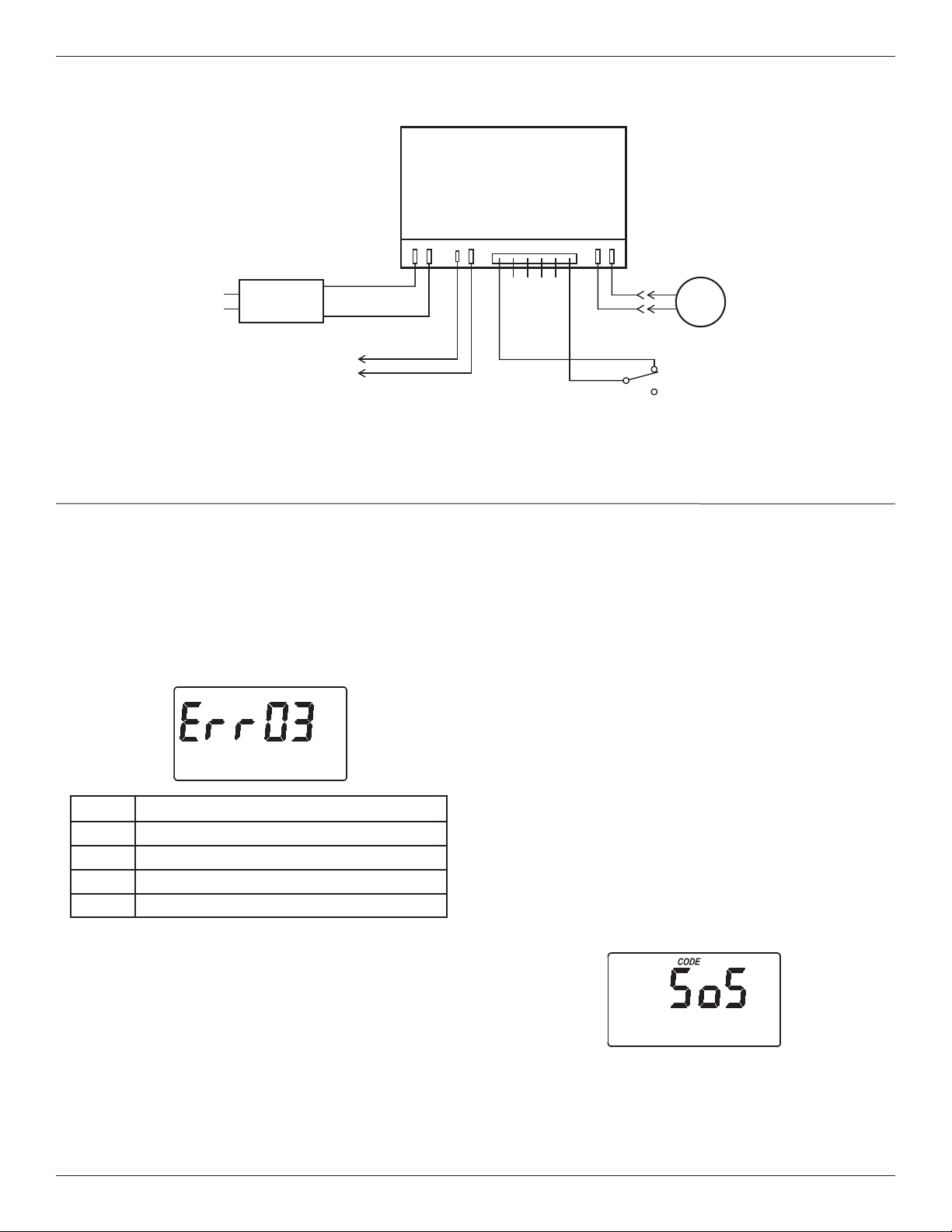
AUTOMATIC ELECTRONIC DIAGNOSTICS
This filter has a self-diagnostic function for the electri-
cal system. The computer monitors electronic com-
ponents and circuits for correct operation. If a mal-
function occurs, an error code appears in the display.
The chart above shows the error codes that could
appear, and the possible malfunctions for each code.
While an error code appears in the display, all buttons
are inoperable except the SELECT button. SELECT
remains operational so the service person can per-
form the Manual Initiated Electronic Diagnostics, see
below, to further isolate the problem.
FIG. 31
Code Possible Problems
Err01 Motor, Valve Position Switch
Err03 Motor, Valve Position Switch, Wire Harness
Err04 Valve Position Switch
Err05 Electronic Control Board (PWA)
TO REMOVE AN ERROR CODE:
1. Unplug the power supply.
2. Correct the problem.
3. Plug the power supply back in.
4. Wait for at least 8 minutes while the timer operates
the valve through an entire cycle. The error code
will return if the problem was not corrected.
RESETTING TO FACTORY DEFAULTS
To reset the electronic controller to its factory default
for all settings (time, days between recharges, etc.):
1. Press the SELECT button and hold it until the dis-
play changes twice to show “CODE” and the flash-
ing model code.
2. Press the r UP button (a few times, if necessary)
to display a flashing “SoS”.
3. Press the SELECT button, and the electronic con-
troller will restart.
4. Set the present time, days between recharges,
etc., as described on pages 10 & 11.
FIG. 32
WIRING SCHEMATIC
FIG. 30
NO
Valve
Motor
Position
Switch
NC
Power Supply
B
ack of Electronic Controller
(PWA)
Power
In
Pos./Turbine
Motor
24V DC
Auxiliary Output
J4
24V DC
120V AC
60 Hz
C
org
grn
Schematic
Loading ...
Loading ...
Loading ...