Loading ...
Loading ...
Loading ...
4
English
4. PREPARATION BEFORE INSTALLATION
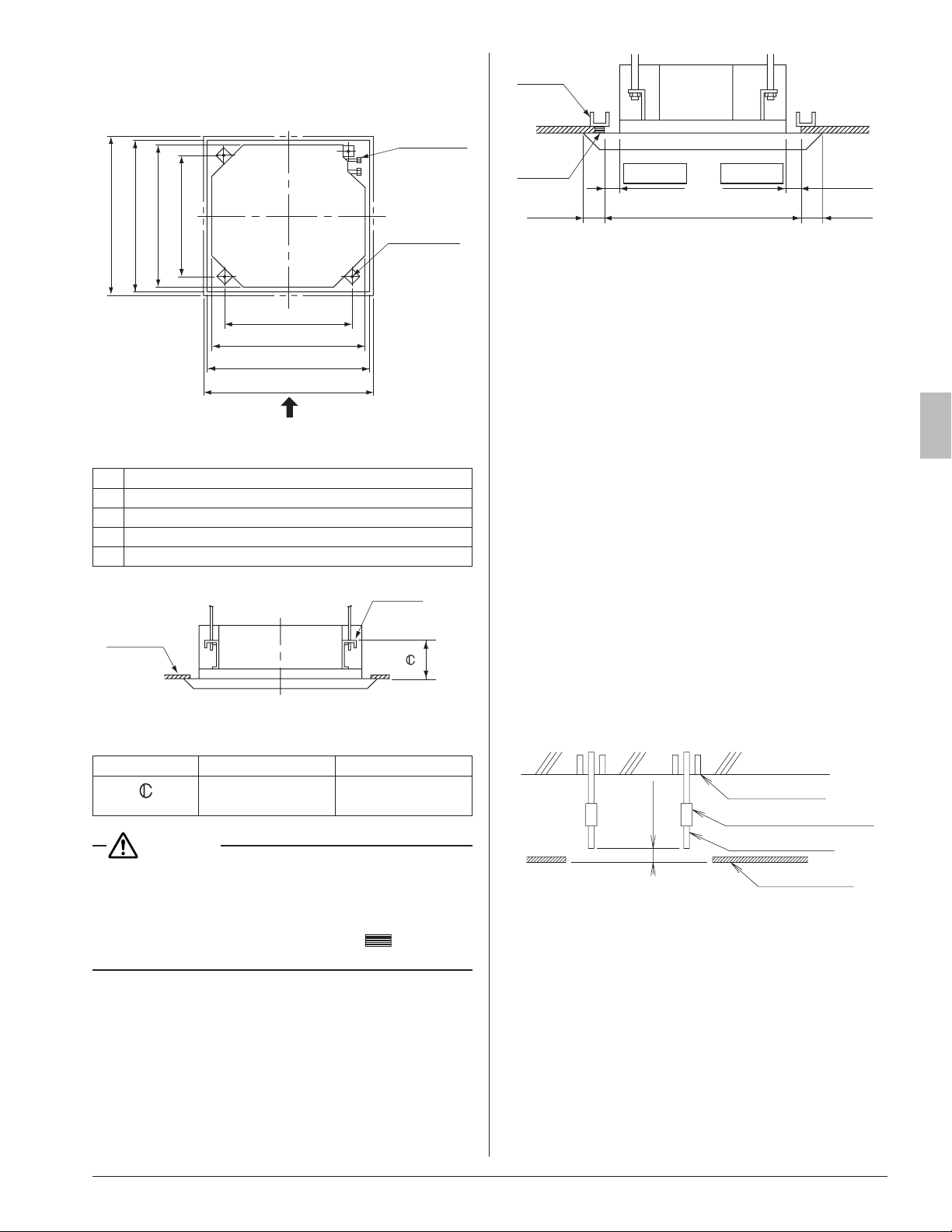
(1) Check the relation of location between the ceiling
opening and the indoor unit suspension bolts.
1 Decoration panel
4 Suspension bolt pitch
3 Indoor unit
2 Ceiling opening
1 Decoration panel
2 Ceiling opening
3 Indoor unit
5 Suspension bolt pitch
Refrigerant
piping
Suspension
bolt (×4)
A
Fig.4
[unit: in. (mm)]
1 37-3/8 (950)
2 33-7/8 – 35-7/8 (860 – 910)
3 33-1/16 (840)
4 30-3/4 (780)
5 28 (710)
Ceiling
View as seen from A
Hanger
Fig. 5
Decoration Panel
BYCQ125B-W1 BYCQ125BGW1
in. (mm)
4-15/16 – 5-1/8
(125 – 130)
8-1/16 – 8-1/4
(205 – 210)
CAUTION
Reduce the distance between the unit and ceiling to
1-3/8 in. (35 mm) or below in order to maintain an over-
lapping panel margin 13/16in. (20 mm) for the opening
on the ceiling. If the distance exceeds 1-3/8in. (35mm),
attach ceiling material to the part marked
or replace
the ceiling. (RefertoFig.6)
Frame
≤1-3/8 (35) ≤1-3/8 (35)
33-7/8 to 35-7/8 (860 – 910)
(Ceiling-panel
overlapping
dimension)
Ceiling
material
(Ceiling-opening dimension)
≥13/16
(20)
≥13/16
(20)
[unit: in. (mm)]
Fig.6
(2) Make the ceiling opening required for installation.
• Use the installation pattern paper (5) matched to the
ceiling opening dimension.
• Make the ceiling opening required for installation at
the installation location and carry out refrigerant/drain
piping, power supply wiring, remote controller wiring
(not needed in case of wireless remote con troller) and
wiring between the indoor and outdoor units. (Refer
to each section 6.REFRIGERANTPIPINGWORK,
7.DRAINPIPINGWORK and 8.ELECTRICWIRING
WORK)
• After making the opening, sometimes it is necessary
to reinforce the ceiling framework to maintain a level
ceiling and prevent it from vibrating.
For details, consult with the builder and interior de-
signer.
(3) Install the suspension bolts.
• User either a M8-M10 size bolt or equipment.
• Use hole-in-anchors for the existing bolts and embed-
ded inserts or foundation bolts for new bolts, and x the
indoor unit rmly to the building so that it may withstand
the mass of the unit.
In addition, adjust clearance (2 – 4 in. (50 – 100 mm))
from the ceiling in advance.
<Installation examples>
2 – 4 in.
(50 – 100 mm)
Foundation bolt
Suspension bolt
Ceiling slab
Long nut or turn-buckle
Ceiling surface
Note) The above shown parts are all field supply.
5. INSTALLATION OF INDOOR UNIT
<<It is easy to attach the optional parts (except for deco-
ration panel) before installing the indoor unit. Refer to
also the installation manual attached to the optional
parts.>>
For installation, use the attached installation parts and
speciedparts.
[Install the indoor unit in the order of steps (1), (2), (3), (4), (5),
and (6) in case of a newly built ceiling, or in the order of steps
(1), (3), (4), and (5) in case of an existing ceiling.]
01_EN_3P161684-9U.indd 4 8/8/2018 15:26:50
Loading ...
Loading ...
Loading ...