Loading ...
Loading ...
Loading ...
15
English
10. FIELD SETTING
<<Refer to also the installation manual attached to the
outdoor unit.>>
CAUTION
Before carrying out eld setting, check the items mentioned in
Clause 2: (1) Items to be checked after completion of work
on page2. Check if all the installation and piping works for
the air conditioner are completed.
• Check if the control box covers of the air conditioner are
closed.
< FIELD SETTING >
<<Afterturnonthepowersupply,carryouteldsetting
from the remote controller according to the installation
state.>>
• Carry out setting at 3 places, MODE NO., FIRST CODE
NO. and SECOND CODE NO.
The settings shown by
in the table indicate those
when shipped from the factory.
• The method of setting procedure and operation is shown in
the installation manual attached to the remote controller.
• In case of remote control, for changeover of input to
FORCED OFF or to ON/OFF OPERATION.
[1] Enter into the field setting mode with the remote controller.
[2] Select MODE NO. 22.
[3] Set the FIRST CODE NO. to 1.
[4-1] For FORCE OFF, set the SECOND CODE NO. to 01.
[4-2] For ON/OFF OPERATION, set the SECOND CODE
NO. to 02.
(It is set to FORCE OFF when shipped from the factory.)
• Ask your customer to keep the manual attached to the
remote controller together with the operation manual.
• Do not carry out settings other than those shown in the
table.
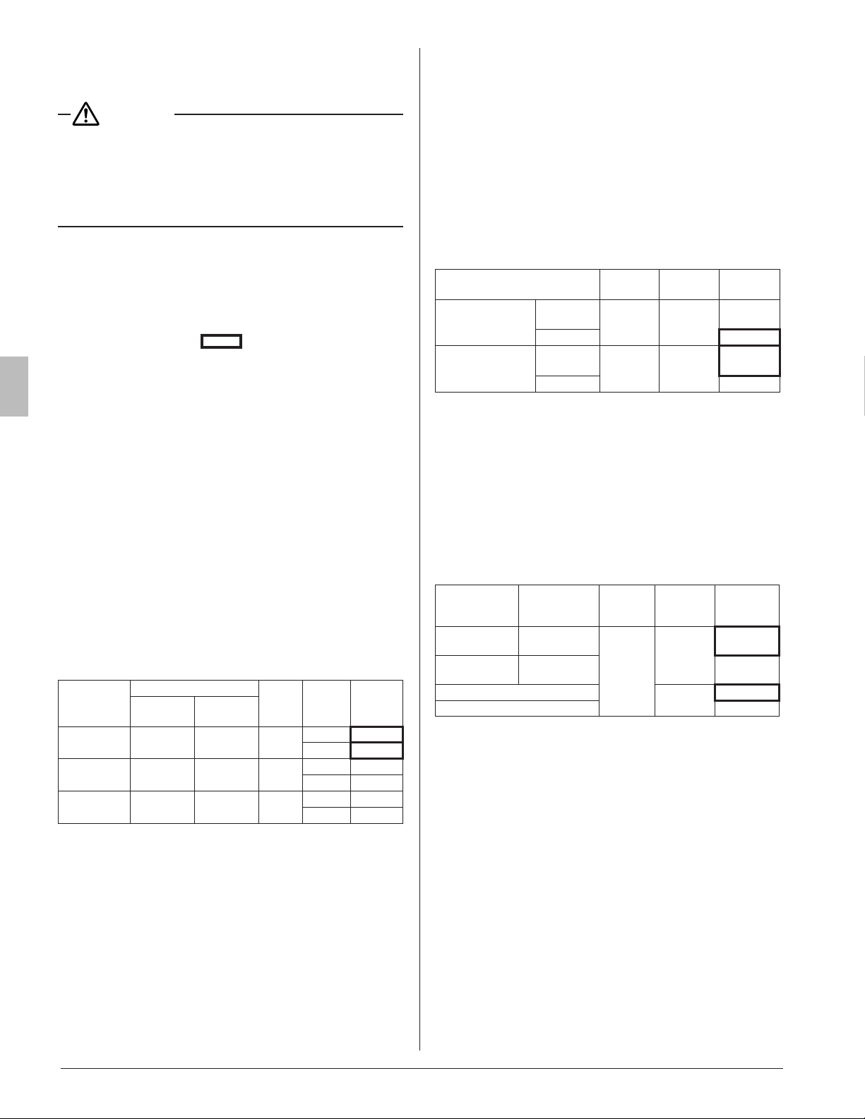
10-1 SETTING CEILING HEIGHT
• Set the SECOND CODE NO. according to the ceiling height
as shown in the Table 4.
Table 4
Setting
Ceiling height [in. (m)]
MODE
NO.
FIRST
CODE
NO.
SECOND
CODE
NO.
18 · 24 type
30 · 36 · 42 · 48
type
Standard
≤ 8 to 3/4
(2.7 or less)
≤ 10 to 1/2
(3.2 or less)
23
0 01
0 01
High ceiling 1
8-3/4 to 10
(2.7 – 3.0)
10-1/2 to 12
(3.2 – 3.6)
23
0 02
0 02
High ceiling 2
10 to 11-1/2
(3.0 – 3.5)
12 to 13-3/4
(3.6 – 4.2)
23
0 03
0 03
10-2 SETTING AIR DISCHARGE DIRECTION
• Refer to the installation manual attached to the sealing ma-
terial of air discharge outlet sold separately and engineer-
ing data book, for ceiling height settings for four-direction
(part of corner closed off) and three-direction.
(The SECOND CODE NO. is factory set to 01 (all round
outlet) before shipping.)
10-3 SETTING WHEN AN OPTIONAL ACCESSORY
IS ATTACHED
• For setting when attaching an optional accessory, refer to
the installation manual attached to the optional accessory.
10-4 WHEN USING WIRELESS REMOTE CON-
TROLLER
• When using a wireless remote controller, it is necessary to
set the wireless remote controller address.
Refer to the installation manual attached to the wireless
remote controller.
10-5 SETTING FAN SPEED DURING THERMO-
STAT OFF
• Set the fan speed according to the using environment after
consultation with your customer.
• When the fan speed is changed, explain the set fan speed
to your customer.
Table 5
Setting
MODE
NO.
FIRST
CODE NO.
SECOND
CODE NO.
Fan speed during
cooling
thermostat OFF
LL
(Extra low)
22 6
01
Setting 02
Fan speed during
heating
thermostat OFF
LL
(Extra low)
22 3
01
Setting 02
10-6 SETTING FILTER SIGN
• A message to inform the air lter cleaning time will be indi-
cated on the remote controller.
• Set the SECOND CODE NO. shown in the Table 6 accord-
ing to the amount of dust or pollution in the room.
• Though the indoor unit is equipped with the long life lter, it
is necessary to periodically clean the lter to avoid clogging
of the lter. Please also explain the set time to the customer.
• The periodic lter-cleaning time can be shortened depend-
ing on the environment.
Table 6
Contamination
Hours until
indication
MODE
NO.
FIRST
CODE NO.
SECOND
CODE
NO.
Normal
Approx.
2,500 hrs
20
0
01
More
contaminated
Approx.
1,250 hrs
02
With indication
3
01
No indication* 02
*
Use
No indication
setting when cleaning indication is not neces-
sary such as the case of periodical clean ing being carried out.
01_EN_3P161684-9U.indd 15 8/8/2018 15:26:58
Loading ...
Loading ...