
Page 1
240-3726
16" Scroll Saw
OPERATOR’S MANUAL
CAUTION: To Reduce The Risk Of Injury, User Must Read
And Understand Operator’s Manual. Save These Instructions
For Future Reference.
For questions / comments, technical assistance or repair
parts - Please call toll free at: 1-877-684-8912 (Monday -
Friday 8am - 6pm EST.)

TABLE OF CONTENTS
Safety Symbols ............................................................................................................................................................
Safety Instructions .......................................................................................................................................................
Overview ......................................................................................................................................................................
Specications ..............................................................................................................................................................
Contents ....................................................................................................................................................................
Assembly ...................................................................................................................................................................
Operation ...................................................................................................................................................................
Maintenance ..............................................................................................................................................................
Troubleshooting .........................................................................................................................................................
Replacement parts list ...............................................................................................................................................
Warranty......................................................................................................................................................................
Page 2
Page 3
Page 8
Page 9
Page 10
Page 11
Page 19
Page 23
Page 25
Page 26
Page 27

Some of these following symbols may be used on this tool. Please study them and learn their meaning. Proper interpretation
of these symbols will allow you to operate the tool better and safer.
SAFETY SYMBOLS
Page 2
WARNING: The operation of any power tool can result in
foreign objects being thrown into your eyes, which can result in severe
eye damage. Before beginning power tool operation, always wear
safety goggles or safety glasses with side shields and a full-face shield
when needed. We recommend a Wide Vision Safety Mask for use over
eyeglasses or standard safety glasses with side shields. Always use
eye protection which is marked to comply with ANSI Z87.1.
Symbol Name Designation / Explanation
V Volts Voltage
A Amperes Current
Hz Hertz Frequency (cycles per second)
W Watts Power
Alternating current Type of current
Direct current Type of characteristic of current
no No-load speed Rotational speed at no load
.../min
Per minute Revolutions, strokes, surface speed orbits, etc., per minute
Be careful of your hand Danger keep hands away from blade
LED worklight Do not stare at operating lamp
Read the operator’s manual Read and understand power tool manual
Wear safety goggles
WARNING: To ensure safety and reliability, all repairs should be performed by a qualied service technician.

The purpose of safety symbols is to attract your attention to possible dangers. The safety symbols and the explanations
with them deserve your careful attention and understanding. The symbol warnings do not, by themselves, eliminate any
danger. The instructions and warnings they give are no substitutes for proper accident prevention measures.
SAFETY INSTRUCTIONS
Page 3
WARNING: Be sure to read and understand all safety instructions in this manual, including all safety alert symbols
such as “DANGER,” “WARNING,” and “CAUTION” before using this tool. Failure to follow all instructions listed below may
result in electric shock, re, and/or serious personal injury.
WARNING: Indicates a potentially hazardous situation, which, if not avoided, could result in death
or serious injury.
CAUTION: Indicates a potentially hazardous situation, which, if not avoided, could result in minor or moderate
injury.
DANGER: Indicates an imminently hazardous situation, which, if not avoided, will result in death or serious injury.
SYMBOL MEANING
SAFETY ALERT SYMBOL: Indicates DANGER, WARNING, OR CAUTION. May be used in conjunction with
other symbols or pictographs.
NOTICE: (Without Safety Alert Symbol) Indicates a situation that may result in property damage.
SAVE THESE INSTRUCTIONS!

PROPOSITION 65 WARNING
Some dust created by using power tools contain chemicals
known to the state of California to cause cancer, birth
defects or other reproductive harm. Some examples of
these chemicals are:
• Lead from lead-based paints.
• Crystalline silica from bricks and cement and other
masonry products, and
• Arsenic and chromium from chemically treated lumber.
Your risk from these exposures varies depending on how
often you do this type of work. To reduce your exposure to
these chemicals: work in a well ventilated area and work
with approved safety equipment, such as dust masks that
are specially designed to lter out microscopic particles.
Avoid prolonged contact with dust from power sanding,
sawing, grinding, drilling, and other construction activities.
Wear protective clothing and wash exposed areas with soap
and water. Allowing dust to get into your mouth or eyes or
to lie on the skin may promote absorption of harmful
chemicals.
Safety is a combination of using common sense, staying
alert, and knowing how your scroll saw works. Read this
manual to understand this scroll saw and how to use
it safely.
GENERAL SAFETY IMFORMATION
GENERAL SAFETY RULES
• KEEP GUARDS IN PLACE and in working order.
• REMOVE ADJUSTING KEYS AND WRENCHES. Form
habit of checking to see that keys and adjusting wrenches
are removed from tool before turning it on.
• KEEP WORK AREA CLEAN. Cluttered areas and benches
invite accidents.
• DON’T USE IN DANGEROUS ENVIRONMENTS. Don’t
use power tools in damp or wet locations, or expose them
to rain. Keep work area well lit.
• KEEP CHILDREN AWAY. All visitors should be kept at a
safe distance from work area.
• MAKE WORKSHOP CHILDPROOF with padlocks, master
switches, or by removing starter keys.
• DON’T FORCE THE TOOL. It will do the job better and
safer at the rate for which it was designed.
• USE THE RIGHT TOOLS. Don’t force tool or attachment
to do a job for which it was not designed.
• WEAR PROPER APPAREL. Do not wear loose clothing,
gloves, neckties, rings, bracelets, or other jewelry that
may get caught in moving parts. Nonslip footwear is
recommended. Wear protective hair covering to contain
long hair.
• ALWAYS USE SAFETY GLASSES. Also use face or dust
mask if cutting operation is dusty. Everyday eyeglasses
only have impact-resistant lenses, they are NOT safety
glasses.
• DON’T OVERREACH. Keep proper footing and balance
at all times.
• MAINTAIN TOOLS WITH CARE. Keep tools sharp and
clean for best and safest performance. Follow instructions
for lubricating and changing accessories.
• DISCONNECT TOOLS before servicing, when changing
accessories, such as knives and motor brushes.
• REDUCE THE RISK OF UNINTENTIONAL STARTING.
Make sure switch is in Off position before plugging in the
planer.
• USE RECOMMENDED ACCESSORIES. Consult the
instruction manual for recommended accessories. The
use of improper accessories may cause risk of injury.
• NEVER STAND ON TOOL. Serious injury could occur if
the tool is tipped or if the cutting tool is unintentionally
contacted.
• CHECK DAMAGED PARTS. Before further use of the tool,
a guard or other part that is damaged should be carefully
checked to determine that it will operate properly and
SAFETY INSTRUCTIONS
Page 4
WARNING: Read and understand all instructions.
Failure to follow all instructions listed below, may result in
electric shock, re and/or serious personal injury. Save all
warnings and instructions for future reference.
WARNING: The use of this tool can generate and/
or disburse dust, which may cause serious and permanent
respiratory or other injury. Always use protection appropriate
for the dust exposure. Direct particles away from the face
and body.
WARNING: To avoid the risk of personal injury,
do not modify this power tool or use accessories not
recommended to t your tool.
CAUTION: Always follow proper operating
procedures as dened in this manual — even if you
are familiar with use of this or similar tools. Remember that
being careless for even a fraction of a second can result in
severe personal injury.
Handling the power cord on this product may expose you
to chemicals known to the State of California to cause
cancer and birth defects or other reproductive harm. Wash
hands after handling.

SPECIFIC SAFETY RULES
perform its intended function. Check for alignment of
moving parts, binding of moving parts, breakage of parts,
mounting, and any other conditions that may affect the
tool's operation. A guard or other part that is damaged
should be properly repaired or replaced.
• DIRECTION OF FEED. Feed work into a knife against the
direction of rotation of the knife only.
• NEVER LEAVE TOOL RUNNING UNATTENDED. TURN
POWER OFF. Don’t leave tool until it comes to a complete
stop.
• DO NOT ALTER OR MISUSE THE TOOL. Any alteration
or modication is considered misuse and may result in
serious personal injury.
BEFORE OPERATING
• Check for proper assembly and proper alignment of
moving parts. Understand the function and proper use
of the ON/OFF switch.
• Know the condition of the scroll saw. If any part is missing,
bent or does not operate properly, replace the component
before you use the scroll saw.
• Determine the type of work you are going to be doing.
Properly protect your body including your eyes, hands,
face and ears.
• To avoid injury cause by pieces thrown from accessories,
use only recommended accessories designed for this saw.
Follow this instruction supplied with the accessory. The
use of improper accessories may cause risk of injury.
• To avoid contact with rotating equipment:
• Do not position your ngers where they could contact
the blade if the workpiece should unexpectedly shift or
your hand should slip.
• Do not cut a workpiece too small to be held safely.
• Do not reach under the scroll saw table when the motor
is running.
• Do not wear loose clothing or jewelry. Roll long sleeves
above the elbow. Tie back long hair.
• To avoid injury from a re hazard, do not operate the scroll
saw near ammable liquids, vapours or gases.
• To avoid back injury:
• Obtain help when it is necessary to raise the scroll saw
more than 10" (25.4 cm). Bend your knees when lifting
the scroll saw.
WHEN OPERATING THE SCROLL SAW
• To avoid injury from unexpected scroll saw movement:
• Use the scroll saw on a rm, level surface with adequate
space for handling and supporting the workpiece.
• Be sure the scroll saw cannot move when operated.
Secure the scroll saw to a workbench or table with wood
screws or bolts with washers and nuts.
• Before moving the scroll saw, unplug the power cord from
the electrical outlet.
• To avoid injury from kickback:
• Hold the workpiece rmly against the tabletop.
• Do not feed the workpiece too fast while cutting. Only
feed the workpiece at the rate the saw will cut.
• Install the blade with the teeth pointing downward.
• Do not start the saw with the workpiece pressing against
the blade. Slowly feed the workpiece into the moving
blade.
• Use caution when cutting round or irregularly shaped
workpieces. Round items will roll and irregularly shaped
workpieces can pinch the blade.
• To avoid injury when operating the scroll saw:
• If you are not thoroughly familiar with the operation of
scroll saws, obtain advice from a qualied person.
• Before starting the saw, make sure the blade tension is
correct. Recheck and adjust tension as needed.
• Make sure the table is locked into position before
starting the saw.
• Do not use dull or bent blades.
• When cutting a large workpiece, make sure the material
is supported at the table height.
• Turn the saw OFF and unplug the power cord if
the blade jams in the workpiece while being backed out.
This condition is usually caused by sawdust clogging
the line you are cutting.
• Do not use if blade guard is damaged or missing.
• Do not clear away cut-off pieces until blade has stopped
and the saw is turned off.
SAFETY INSTRUCTIONS
Page 5
WARNING: This product is not recommended for
drilling.
READ OPERATOR’S MANUAL
To reduce the risk of injury, user must read and
understand operator’s manual before using this product.
• USE SAFETY GOGGLES AND EAR PROTECTION
• ALWAYS WEAR EYE PROTECTION THAT CONFORMS
WITH UL REQUIREMENTS. FLYING DEBRIS can cause
permanent eye damage.
In order to prevent potential electrical shock and injury, the
following electrical safety precautions and symbols should
be followed at all times!
SAFETY INSTRUCTIONS
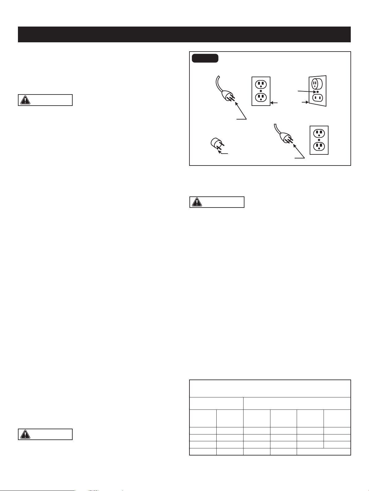
Page 6
WARNING: In case of a malfunction or breakdown,
grounding provides a path of least resistance for electric
current to reduce the risk of electric shock. This tool
is equipped with an electric cord having an equipment-
grounding conductor and a grounding plug. The plug must
be plugged into a matching outlet that is properly installed
and grounded in accordance with all local codes and
ordinances.
FIG. 1
The table below shows the correct size to use, depending
on the cord length and nameplate amperage rating. If
in doubt, use the next heavier gauge. The smaller the gauge
number, the heavier the cord.
Use a proper extension cord. Make sure extension cords
are in good condition. When using an extension cord, be
sure to use a cord that is heavy enough to carry the drawn
current needed by the saw. An undersized cord will cause
a drop in line voltage, resulting in loss of power and
overheating.
GUIDELINES FOR EXTENSION CORDS
This tool has a precision-built electric motor. It should be
connected to a power supply that is 120 volts, 60 Hz. A
substantial voltage drop will cause a loss of power and the
motor will overheat. If the tool does not operate when plugged
into an outlet, double check the power supply.
• Do not modify the plug provided – if it will not t the outlet;
have the proper outlet installed by a qualied electrician.
• Improper connections of the equipment-grounding
conductor can result in a risk of electric shock. The
equipment-grounding conductor is the insulated conductor
that has an outer surface that is green, with or without
yellow stripes. If repair or replacement of the electric cord
or plug is necessary, do not connect the equipment-
grounding conductor to a live terminal
• Check with a qualied electrician or service personnel if
the grounding instructions are not completely understood,
or if in doubt as to whether the tool is properly grounded.
• Use only 3-wire extension cords that have 3-prong
grounding plugs and 3-pole receptacles that accept the
tool’s plug.
• Repair or replace a damaged or worn cord immediately.
ELECTRICAL CONNECTION
WARNING: Do not permit ngers to touch the
terminal or the plug when installing or removing the plug
from an outlet.
GROUNDING INSTRUCTIONS
MINIMUM GAUGE (AWG)
EXTENSION CORDS (120V use only)
Amperage rating
Total length
Not Recommended
Not more
than
25'
(7.5 m)
6 18
50'
(15 m)
16
100'
(30 m)
16
150'
(45 m)
14
More
than
0
10 18 16 14 126
12 16 16 14 1210
16 14 1212
Grounded, cord-connected tools intended for use on a
supply circuit having a nominal rating less than 150 Volts:
• This tool is intended for use on a circuit that has an outlet
that looks like the one shown in Sketch A of Figure 1. The
tool has a grounding plug that looks like the plug illustrated
in Sketch A of Figure 1.
• A temporary adapter, which looks like the adapter
illustrated in sketches B and C, may be used to connect
this plug to a 2-pole receptacle as shown in Sketch B, if
a properly grounded outlet is not available. The temporary
adapter should be used only until a properly grounded
outlet can be installed by a qualied electrician. The
greencolored rigid ear, lug, and the like, extending from
the adapter, must be connected to a permanent ground
such as a properly grounded outlet box.
WARNING: Use of a temporary adapter is not
permitted in Canada.
Grounding
Pin
Metal
Screw
Cover Of
Grounded
Outlet Box
Adaptor
Grounding
Means
(A)
Circuit and Adapter Information
Grounding
Pin
(D)
(B)
(C)

SAFETY INSTRUCTIONS
Page 7
guided by a fence, miter gauge or other aid. Workpiece
must supported by the work table.
• ON/OFF Switch: Allows the operator to turn ON/OFF the
scroll saw easily, and it turns the dust blower on and off.
• Bevel Scale and Bevel Indicator: The bevel scale and
bevel indicator show the angle of the saw blade with
respect to the work table.
• Storage Compartment: Located under the left side of the
work table used for storage of small accessories such as
saw blades or hex keys.
• Blade Tension Knob: Loosen or tighten blade tension by
pushing the blade tension knob up or down.
• Drop Foot and Drop Foot Lock Knob: The drop foot
should be lowered until it just rests on top of the workpiece
to prevent the workpiece from lifting, yet not so much that
the workpiece drags. The vertical portion provides a blade
protector to prevent accidental blade contact.
• Variable Speed Knob: Turn the knob to adjust the speed
from the high speed of approximately 1600 RPM to the
low speed of approximately 400 RPM.
• Dust Blower: The dust blower keeps the line of cut on the
workpiece clean for more accurate scroll cuts. For best
results, always direct air ow at the blade and
the workpiece.
• LED Light: With an easy ON/OFF switch, the LED light
keeps the line of cut on the workpiece lit for more accurate
scroll cuts.
• Dust Extraction Port: This feature will alow you to attach
the vacuum hose for easy dust collection.
• LED Light Switch: A power switch that turns the LED
light on and off.
• Bevel Lock Knob: Allows you to tilt the table and lock it
at the desired angle, up to 45° right and left.
• Upper and Lower Blade Holders: Upper and lower blade
holders provide support and location of the saw blade.
• Table Insert: The table insert is located on the table slot
to support the workpiece with respect to the blade.
It prevents movement of the workpiece from the work table.
• Work Table: The surface where the workpiece is attached
to while performing cutting operations.
• To Avoid Injury from Kickback:
• Hold the workpiece rmly against the tabletop.
• Do not feed the workpiece too fast while cutting. Only
feed the workpiece at the rate the saw will cut.
• Install the blade with the teeth pointing downward.
• Do not start the saw with the workpiece pressing against
the blade. Slowly feed the workpiece into the moving
blade.
• Use caution when cutting round or irregularly shaped
work pieces. Round items will roll and irregularly shaped
work pieces can pinch the blade.
Be sure extension cords are properly wired and in good
condition. Always replace a damaged extension cord
or have it repaired by a qualied technician before using it.
Protect extension cords from sharp objects, excessive heat,
and damp or wet areas.
WARNING: Keep the extension cord clear of the
working area. Positon the cord so that it will not get caught
on lumber, tools, or other obstructions while you are working
with a power tool. Failure to do so can result in serious
personal injury.
WARNING: Check extension cords before each
use. If damaged replace immediately. Never use tool with
a damaged cord since touching the damaged area could
cause electrical shock resulting in serious injury.
WARNING: To avoid electrical hazards, re hazards,
or damage to the tool, use proper circuit protection.
Use a separate electrical circuit for power tools. This circuit
should be protected with a time delayed fuse. Before
connecting the tool to the power line, make sure the switch
is in the OFF position and the electric current is rated the
same as the current stamped on the motor’s nameplate.
Running at a lower voltage will damage the motor.
The safe use of this product requires an understanding of
the information on the tool and in this operator’s manual as
well as a knowledge of the project you are attempting.
Before use of this product, familiarize yourself with all
operating features and safety rules.
GLOSSARY OF TERMS
• Saw Blade: The saw blade furnished with the scroll saw
is a carbide-tipped combination blade that is 133 mm
long, 2.6 mm wide and has 18 teeth per inch. It is used
for producing a good quality cut for may applications.
• Blade Width: The width of the blade is the distance from
the tip of a tooth to back of the blade.
• Blade Thickness: The blade thickness is the distance
between sides of blade. A thicker blade has more rigidity
and stronger teeth. A narrow, thick blade is used to make
curves and a wide, thin blade is used to make long,
straight cuts.
• Blade Pitch: The blade pitch is the number of teeth per
inch or tooth size. A blade with more teeth per inch
produces a smoother cut. The type of material to be cut
determines the number of teeth that should be in contact
with the workpiece.
• Freehand: Performing a cut without the workpiece being
45
30
15
Page 8
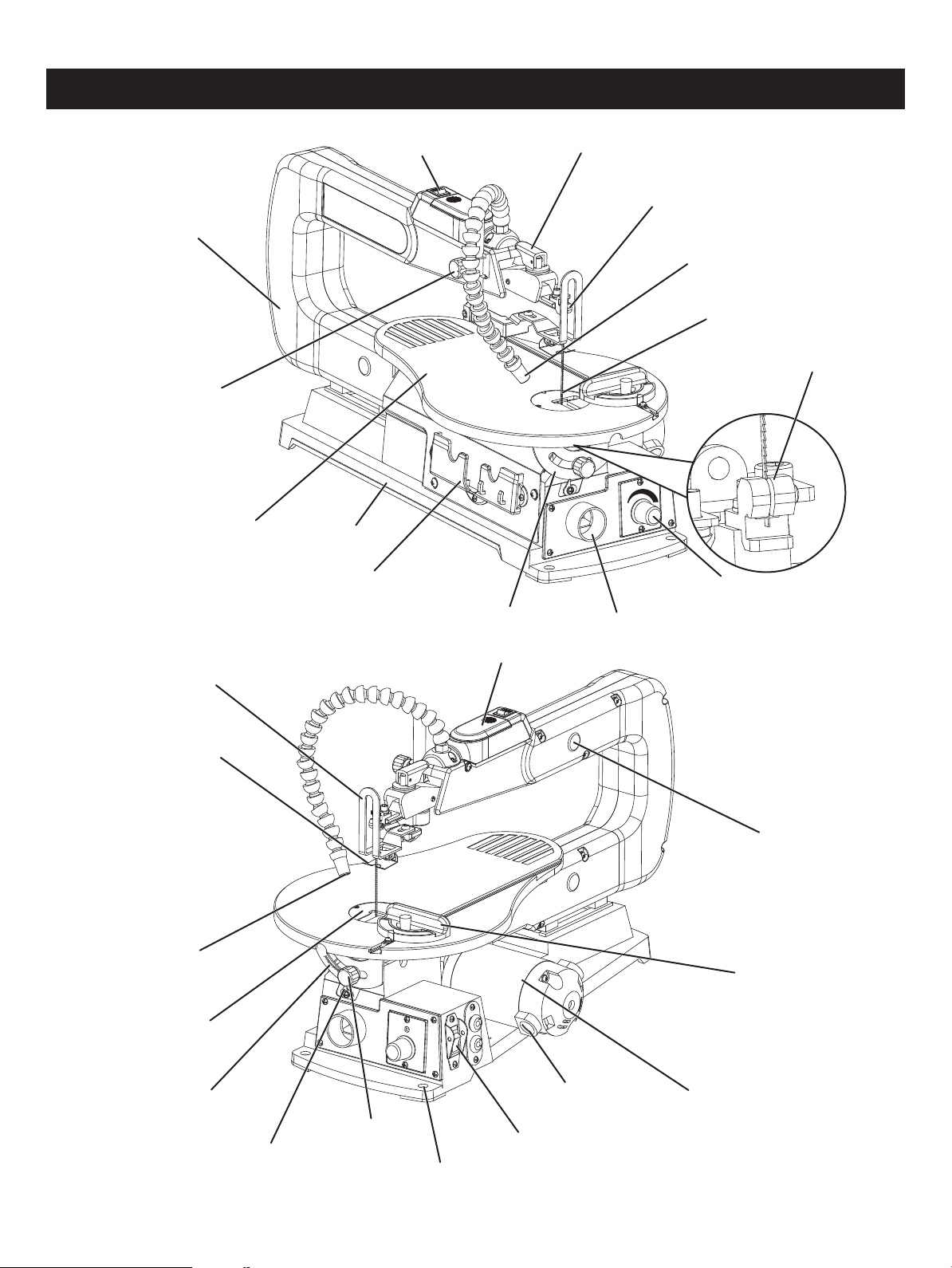
OVERVIEW
ON/OFF switch
LED light switch
Work table
Drop foot lock knob
Drop foot
Blade protect board
Bevel scale
Mounting hole
Bevel indicator
Upper blade holder
Dust blower
Blade tension lever
Saw blade
Lower blade holder
Motor
Saw arm
Battery compartment cover
Miter gauge
Table insert
LED light
Brush cap
Variable speed knob
Angle gauge
Base
Dust extraction port
Storage compartment
Bevel lock knob
Rubber bearing cover

Page 9
Motor
Blade speed
Blade length
Blade width
120 V~ 60 Hz 1.2A
400-1600 SPM
5-1/4"
3/32"
Table size 15" x 10" (380 x 250mm)
0-45° (left) & 0-15° (right)
Table tilting angle
Max. cutting depth 2"
Max. cutting width 16"
Weight 27.7 lbs (12.6 kg)
SPECIFICATIONS
Page 10
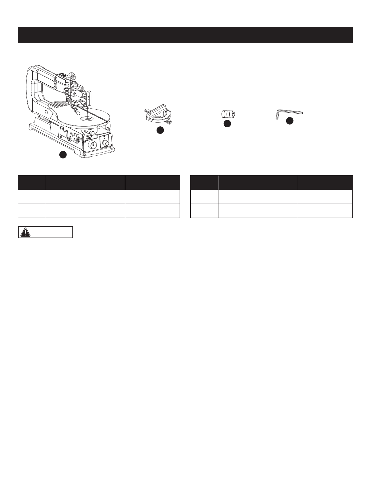
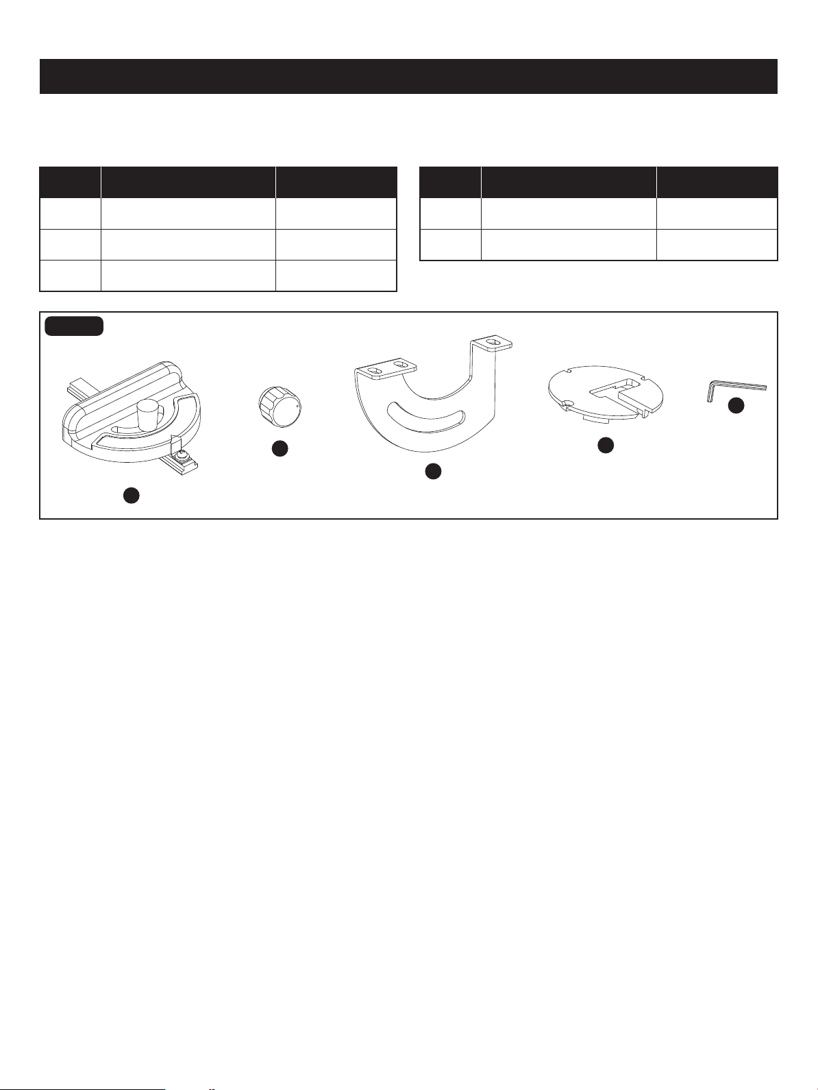
CONTENTS
WARNING: The use of attachments or accessories not listed in this manual might be hazardous and could cause
serious personal injury.
A 1Scroll Saw Assembly
The following items are included with your 16" Scroll Saw:
A
B
C
D
PART DESCRIPTION QUANTITY
B 1Miter Gauge
C 2Blade Clamp Screw
PART DESCRIPTION QUANTITY
D 12.5 mm Hex Key
WARNING: To avoid injury, do not connect this scroll saw to a power source until it is completely assembled and
adjusted and you have read and understood the operator’s manual.
(ITEMS NOT SUPPLIED)
Star-head screwdriver
UNPACKING YOUR SCROLL SAW
YOU WILL NEED
• Unpack all parts and lay them on a at, stable surface.
• Remove all packing materials and shipping devices if applicable.
• Make sure the delivery contents are complete and free of any damage. If you nd that parts are missing or show damage
do not use the product but contact your dealer. Using an incomplete or damaged product represents a hazard to people
and property.
• Ensure that you have all the accessories and tools needed for assembly and operation. This also includes suitable
personal protective equipment.
WARNING: The use of attachments or accessories not listed in this manual might be hazardous and could cause
serious personal injury.
WARNING: Do not attempt to modify this tool or create accessories not recommended for use with this tool. Any
such alteration or modication is misuse, and could result in a hazardous condition leading to possible serious personal
injury.
WARNING: Do not connect to the power supply until assembly is complete. Failure to comply could result in
accidental starting and possible serious personal injury.
Page 11
ASSEMBLY
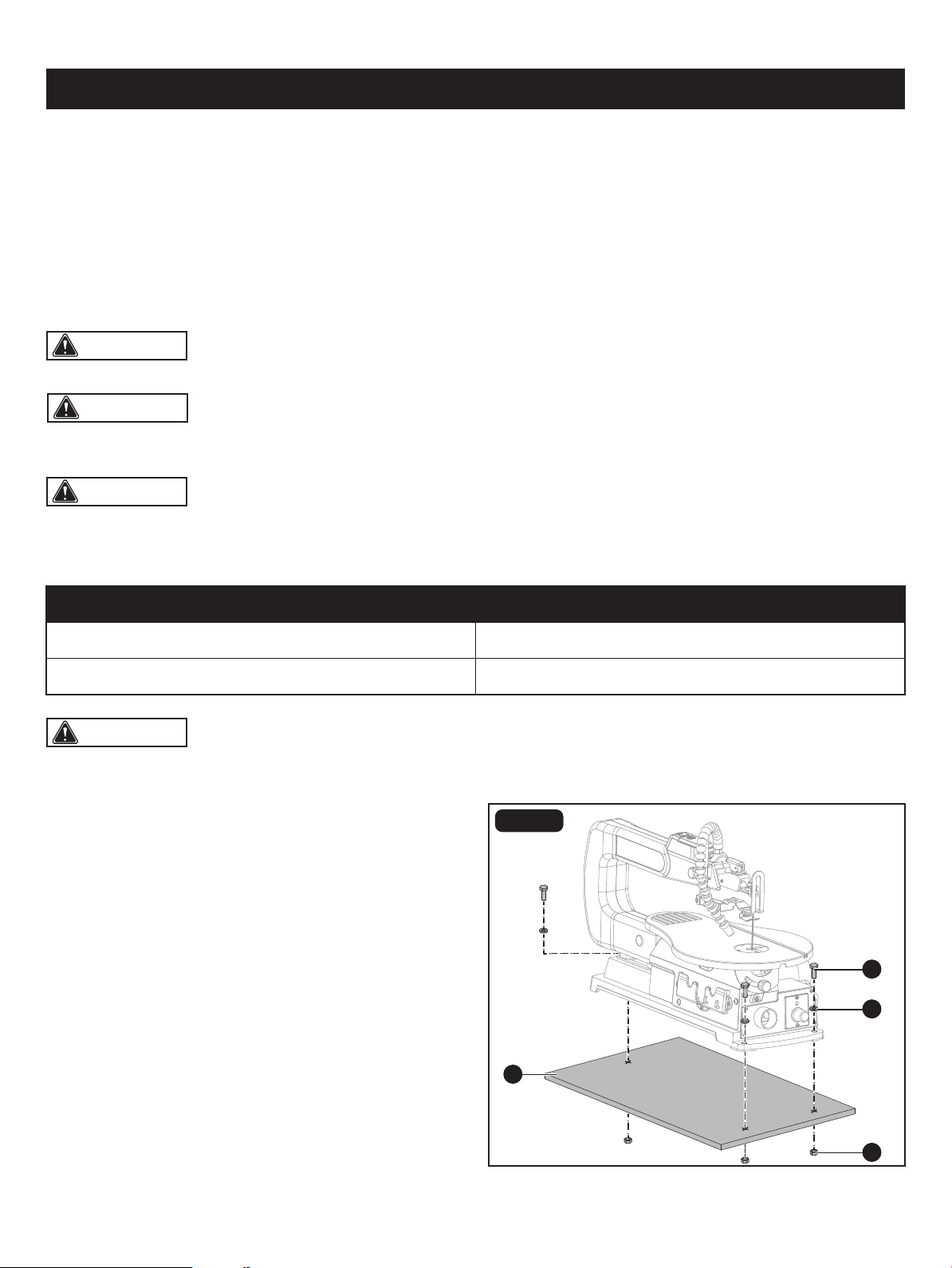
FIG. 2
MOUNTING SCROLL SAW TO
WORKBENCH (Fig. 2)
If the scroll saw is to be used in a permanent application,
we recommend that you secure it in a permanent location
such as a workbench. Three bolt holes have been provided
in the saw’s base for this purpose. When mounting the saw
to a workbench, holes should be drilled through the supporting
surface of the workbench.
A
C
B
D
10mm Open-end wrench or Adjustment wrench
2.5mm Hex key
Combination square
• Each hole in the base of the saw should be bolted securely
using hex bolts (A), locking washers (B) and hex nuts (C)
(not included). Bolts should be of sufcient length to
accommodate the saw base, washers, nuts and the
thickness of the workbench (D).
Page 12
ASSEMBLY
CAUTION: All bolts should be inserted from the top. Install the washers and nuts from the underside of the bench.
FIG. 3
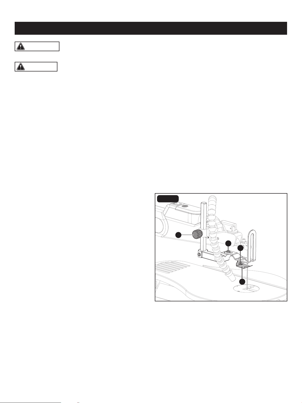
DROP FOOT ADJUSTMENT (Fig. 3)
To prevent workpiece from lifting, the drop foot (A) should
be rest at above the workpiece and the drop foot adjusted
so it is parallel to the working table when angle cutting. The
drop foot should not be adjusted so that the workpiece
drags.
Always retighten the drop foot lock knob (B) after each
adjustment has been made.
• To adjust, loosen the screw (C), tilt the drop foot (A) so it
is parallel to the working table, and tighten the screw.
• Loosen the drop foot lock knob (B) to raise or lower the
drop foot until it just rests on top of the workpiece. Tighten
the knob.
• Loosen the horizontal adjustment screw (D) with screw-
driver (not included), then move the drop foot forward or
backward as needed.
The tall, front part of the drop foot acts as a blade protector
to prevent accidental contact with the blade.
WARNING: To avoid serious personal injury from unexpected tool movement, always secrurely mount scroll saw
to a workbench.
D
C
A
B
• Place scroll saw on workbench. Using the saw base as a pattern, locate and mark the holes where the scroll saw is to
be mounted.
• Drill four holes through the workbench.
• Place scroll saw on workbench, aligning holes in the saw base with the holes drilled in the workbench.
• Insert all four bolts and tighten securely with washers and nuts.
Supporting surface where scroll saw is mounted should be examined carefully after mounting to insure that no movement
during use can result. If any tipping or walking is noted, secure workbench or supporting surface before beginning cutting
operations.
Reducing Noise and Vibration:
You may wish to place a foam pad or piece of carpet between the saw base and the workbench to help reduce noise and
vibration.
If a foam pad or piece of carpet is used, do not overtighten the mounting bolts. Leave some cushion between the padding
and the saw base to help absorb the noise and vibration.
The thickness of the padding material should be approximately 1/2" (13 mm).
Page 13
ASSEMBLY
CAUTION: If the LED light will not be used for more
than three months, remove the batteries in order to avoid
damage from possible leakage.
CAUTION: Do not stare at operating lamp.
FIG. 4
FIG. 5
FIG. 6
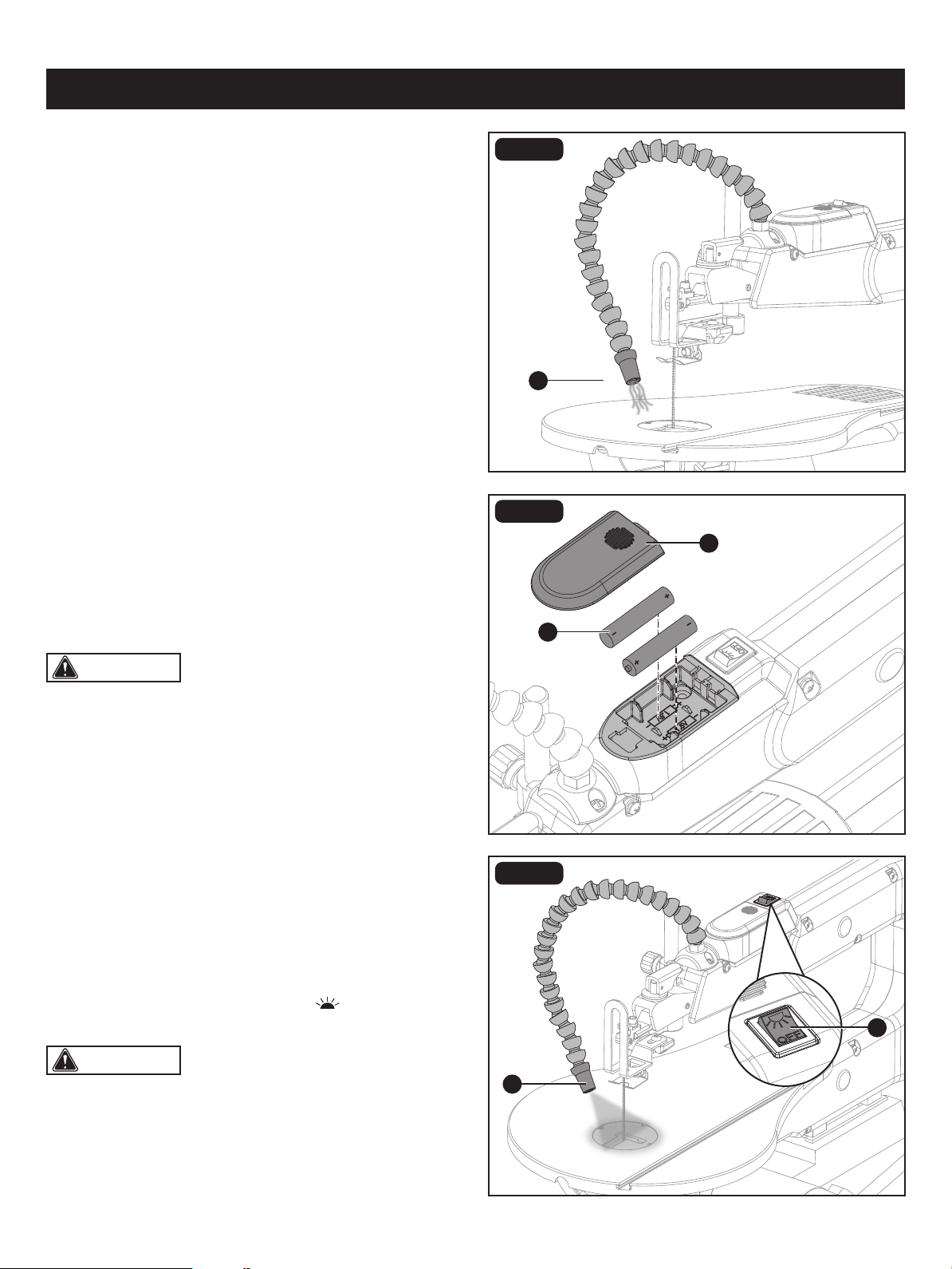
DUST BLOWER ADJUSTEMT (Fig. 4)
The attached dust blower (A) is designed to direct air to the
cutting line. Adjust the dust blower to the desired position.
For the best results, always direct air ow at the blade and
the workpiece.
INSTALLING BATTERIES FOR LED LIGHT
(Fig. 5)
• Remove battery compartment cover (A).
• Install two AAA batteries (B) (not included) according to
polarity indicators inside the battery compartment.
• Replace the battery compartment cover (A).
LED LIGHT ADJUSTEMT (Fig. 6)
With an easy ON/OFF switch (A), the attached LED light (B)
keeps the cutting line on the workpiece lighted for more
accurate scroll cut. Adjust the LED light to the desired
position.
• To turn on the LED light, press the “ ” button.
• To turn off the LED light, press the “OFF” button.
A
B
A
A
B
45
30
15
0
Page 14
ASSEMBLY
CAUTION: Make practice cuts on scrap wood to
check if the bevel angle settings are correct before important
angle cuts.
FIG. 6a
FIG. 6b
FIG. 6c
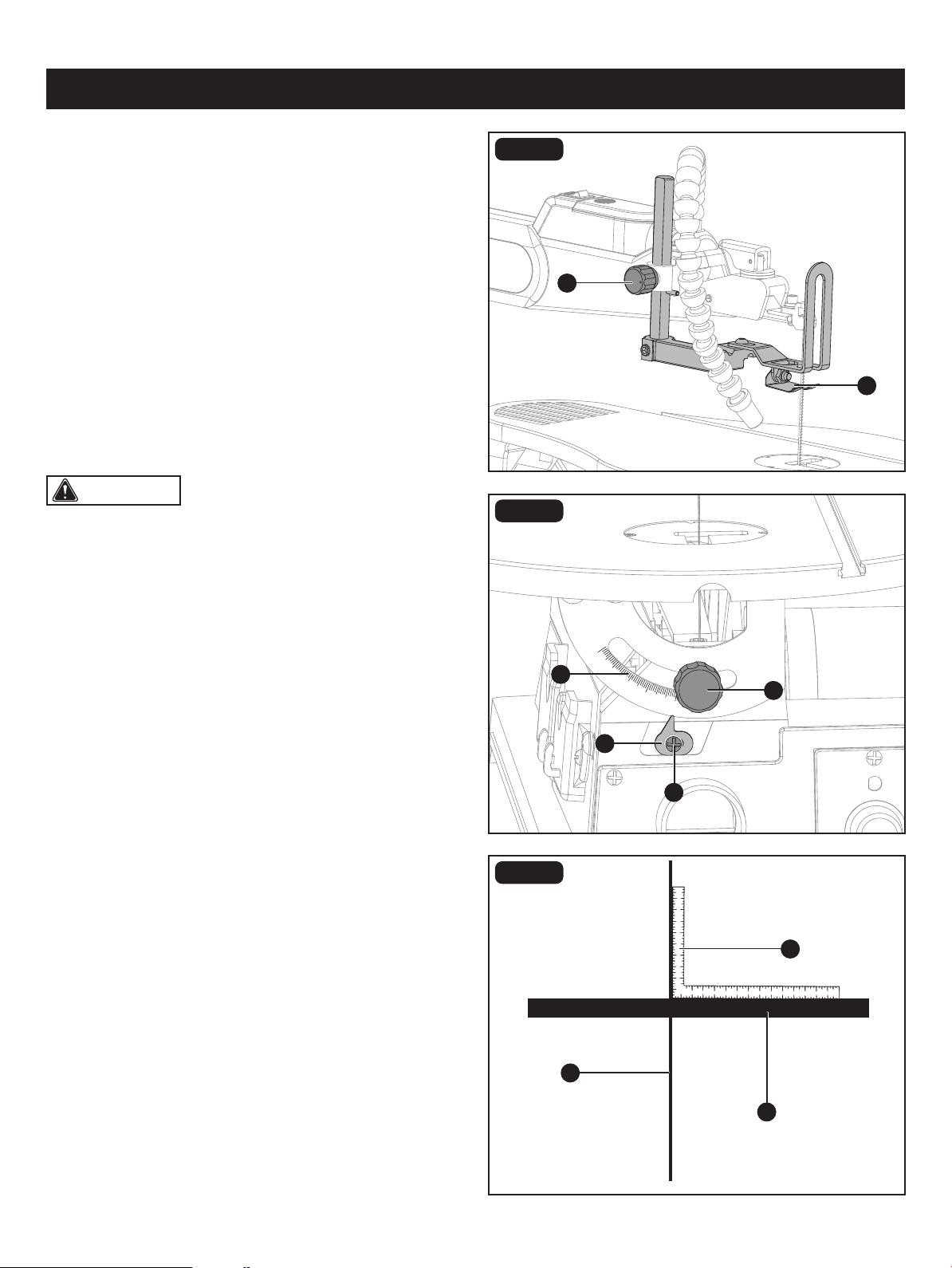
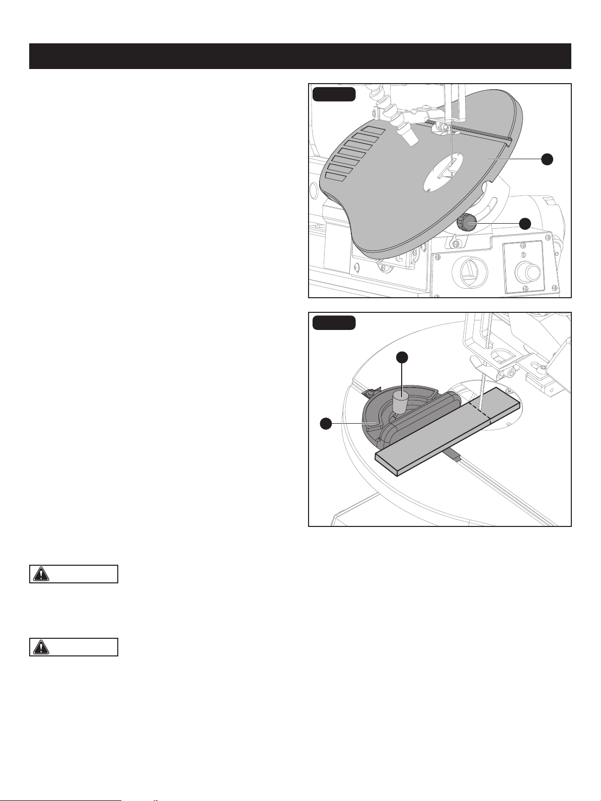
SQUARING THE WORK TABLE TO THE
BLADE (Fig. 6a-6c)
• Loosen drop foot lock knob (A), move the drop foot
assembly(B) upward as far as possible.
• Loosen the bevel lock knob (C) to tilt the work table until
it is approximately perpendicular or at right angle to the
blade.
• Place a combination square (D) on the work table (E) next
to the saw blade (F).
• Loosen the screw (G) holding the bevel indicator (H). Move
indicator to the 0° mark and securely tighten screw.
Remember, the bevel scale (I) is a convenient guide but
should not be relied upon for precision. Make practice
cuts on scrap material to determine if your angle settings
are correct.
B
C
D
H
F
I
A
G
E

Page 15
ASSEMBLY
CAUTION: Any and all servicing should be performed by a qualied service center.
CAUTION: Thinner blades are more susceptible to blade deection when cutting angles are not perpendicular to
the table.
BLADE SELECTION
This scroll saw accepts pin-end and plain end blades with a wide variety of blade thicknesses and widths. The type of
material and intricacies of cutting operations will determine the number of teeth per inch.
Always select the narrowest blades for intricate (tight radius and curves) curve cutting and the widest blades for straight
and large curve cutting operations.
The following table represents suggestions for various materials. When purchasing blades, refer to the back of the package
for best use of blades on various materials.
Use this table as an example, but practice and your own personal preference will be the best selection method.
BLADE CARE
To maximize the life of your scroll saw blades:
• Do not bend blades when installing.
• Always set proper blade tension.
• Use the right blades (See instructions on replacement blade packaging for proper use.)
• Feed the workpiece correctly into the blade.
• Use thin blades for intricate cutting.
When choosing a blade, use very ne, narrow blades to scroll cut in thin wood 1/4" thick or less. Use wider blades for
thicker materials but this will reduce the ability to cut tight curves.
Teeth/inch
TPI
Blade width
Inch
Blade thickness
Inch
Blade/SPM
Material cut
10 0.110 0.020 1200-1600
Popular size for cutting hard and
soft woods 3/16" up to 2" plastics,
paper, felt, bone, etc.
15 0.110 0.020 600-1200
Wood, plastic, extremely thin cuts
on materials 3/32" to 1/2" thick
18 0.095 0.010 400-600
For tight radius work in thin
material 3/32" to 1/8" wood
veneer, wood, bone, Fiber, ivory,
plastic, and etc.
Page 16
ASSEMBLY
CAUTION: To prevent personal injury, always turn
saw OFF and disconnect the plug from the power source
before changing blades.
CAUTION: Make sure the blade is properly located in the blade holders.
CAUTION: Adjust the blade tension after push down the blade tension lever. If not, blade may be broken.
WARNING: Blade teeth are sharp. Be careful when
handling the blade.
WARNING: When installing pin-end blades, the
slot on the blade holder must be slightly wider than
the thickness of the blade. After the blade is installed, the
blade tension lever will keep it in place.
FIG. 8a
FIG. 8b
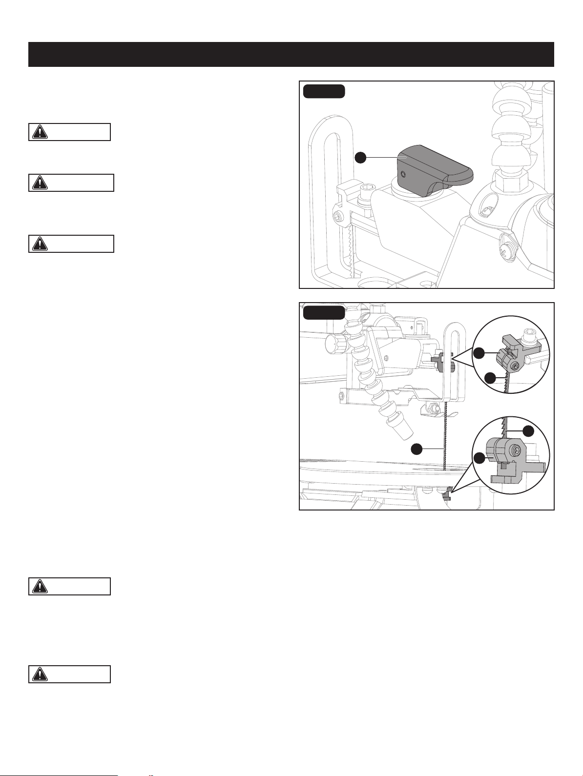
BLADE REMOVAL AND INSTALLATION
(Fig. 8a-8d)
PIN-END BLADE (Fig. 8a-8b)
To remove a blade:
• Unplug the saw.
• Release the blade tension by lifting up the blade tension
lever (A).
• Lift the saw blade (B) out by pulling forward on blade,
then lifting the blade from the upper blade holder (C) and
lower blade holder (D). Slight downward pressure against
the upper arm may be helpful when removing blade from
upper blade holder.
To install a blade:
• Place the new blade through the opening in the table
insert with the teeth to the front of the saw and pointing
down toward the work table.
• Hook the new blade in the recess of the lower blade holder (D).
• Pull up on the blade, press down on the upper arm and position the upper end of the blade in the slot on
the upper holder (C).
Pin-end blades are thicker for stability and for faster
assembly. They provide faster cutting on a variety of
materials.
• Push down the blade tension lever (A).
• Adjust the blade tension by turning the blade tension lever. Turn it clockwise will increase blade tension and
turn it counterclosewise will reduce blade tension.
Note: when blade is too tight or not installed, it may viberate.
A
C
B
D
C
C
45
30
15
0
FIG. 8c
FIG. 8d
ASSEMBLY
Page 17
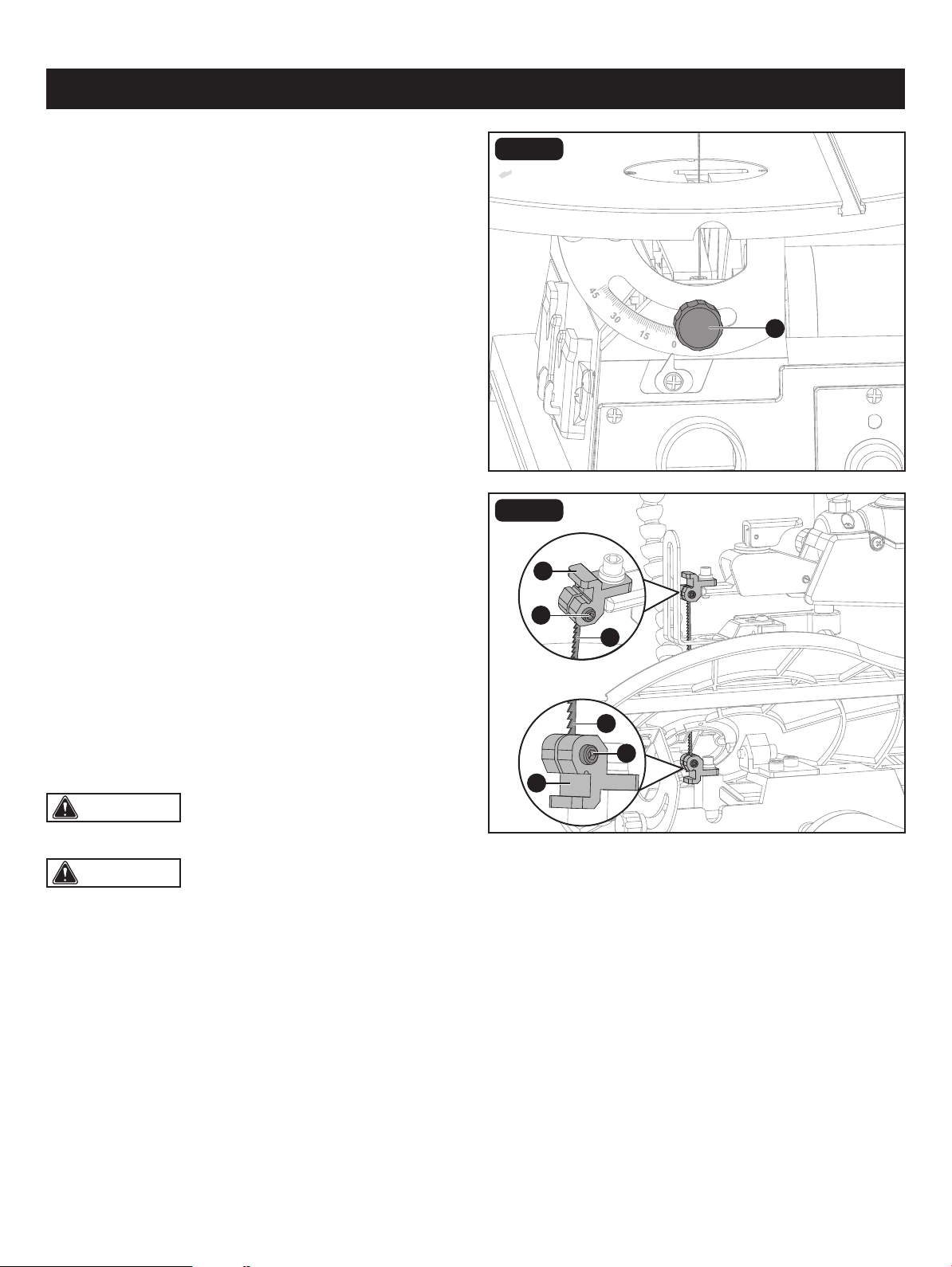
PLAIN END BLADE (NOT INCLUDED)
(Fig. 8a, 8c-8d)
To remove a blade:
• Unplug the saw.
• Release the blade tension by lifting up the blade tension
lever (A). (Fig. 8a)
• Loosen the bevel lock knob (E) counter-clockwise to tilt
the work table until it is 45° left.
• Loosen the upper blade screw (F) and lower blade clamp
screw (G) with 2.5mm hex key (supplied).
• Lift the saw blade (B) out by pulling forward on blade,
then lifting the blade from the upper blade holder (C) and
lower blade holder (D). Slight downward pressure against
the upper arm may be helpful when removing blade from
upper blade holder.
To install a blade:
• Keep the new blade (B) in the recess of the lower blade
holder (D).
• Gently tighten the lower blade clamp screw (G).
• Pull up on the blade, press down on the upper arm and
position the upper end of the blade in the upper holder (C).
• Gently tighten the upper blade clamp screw (F). Make
sure the blade is properly located in the blade holders.
Tighten both the upper and lower clamp screws.
• Push down the blade tension lever (A).
• Adjust the blade tension by turning the blade tension lever.
Turn it clockwise will increase blade tension and turn it
counterclosewise will reduce blade tension.
• Tilt the work table until it is 0° and tighten the bevel lock
knob (E).
CAUTION: when blade is too tight or not installed,
it may viberate.
CAUTION: Adjust the blade tension after push
down the blade tension lever. If not, blade may be broken.
B
B
G
D
C
F
E
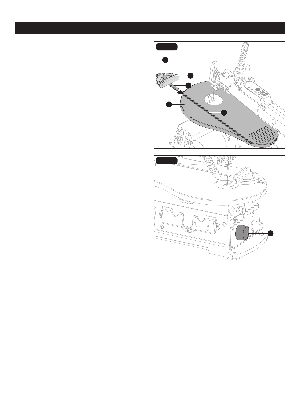
FIG. 9
FIG. 10
ASSEMBLY
INSTALLING THE MITER GAUGE (Fig. 9)
• Sldie the rod (A) on the miter gague (B) into the groove
(C) on the work table (D).
• Loosen the lock knob (E) turn the miter gauge into desired
angle.
DUST EXTRACTION PORT (Fig. 10)
• This scroll saw allows a hose or vacuum accessory
(not provided) to be connected to the dust-extraction port
(A) at the front of the saw.
• If excessive sawdust buildup occurs inside the base, use
a wet/dry vacuum cleaner or manually remove sawdust.
This will keep your saw cutting efciently.
E
C
D
A
B
A
Page 18

WARNING: Before removing loose pieces from the table or making adjustments, turn saw off and wait for all
moving parts to stop to avoid serious personal injury.
BASIC OPERATION OF THE SCROLL SAW
Before starting a cut, watch the saw run. If you experience excessive vibration or unusual noise, stop immediately. Turn
the saw off, remove the switch key, and unplug the saw. Do not restart until locating and correcting the problem.
CUTTING PROCEDURES
• There is a learning curve for each person who wants to use this saw. During that period of time it is expected that some
blades will break until you learn how to use and adjust the saw.
• Plan the way you will hold the workpiece from start to nish.
• Keep your hands away from the blade. Do not hand hold pieces so small your ngers will go under the blade protect
board.
• Hold the workpiece rmly against the work table.
• The blade teeth cut material only on the down stroke.
• Use gentle pressure and both hands when feeding the work into the blade. Do not force the work.
• Guide the workpiece into the blade slowly because the teeth of the blade are very small and can only remove material
on the down stroke.
• Avoid awkward operations and hand positions where a sudden slip could cause serious injury from contact with the blade.
Never place hands in blade path.
• To get accurate cuts, compensate for the blade's tendency to follow the wood grain as you are cutting wood.
• Use extra supports (tables, saw horses, blocks, etc.) when cutting large, small or awkward workpieces.
• Never use another person as a substitute for a table extension or as additional support for a workpiece that is longer or
wider than the basic saw table.
• When cutting irregularly shaped workpieces, plan your work so it will not pinch the blade. Workpieces must not twist,
rock or slip while being cut.
REMOVING JAMMED MATERIAL
When backing out the workpiece, the blade may bind in the kerf (cut). This is usually caused by sawdust clogging the kerf
or when the blade comes out of the blade holders. If this happens:
AVOIDING INJURY
• Make sure saw is level and does not rock. Saw should always be on a rm, level surface with plenty of room for handling
and properly supporting the workpiece.
• Bolt saw to the support surface to prevent slipping, walking or sliding during operations like cutting long, heavy boards.
• Turn saw off and unplug cord from the power source before moving the saw.
• Do not remove jammed pieces until blade has come to a full and complete stop.
• Choose the right size and style blade for the material and type of cut you plan to do.
• Use only recommended accessories.
• Wait until the saw has come to a full and complete stop.
• Place the switch in the off position.
• Unplug the saw from the power source.
• Remove the saw's blade and the workpiece, refer to section on “blade removal and installation.”
• Wedge the kerf open with a at screwdriver or wooden wedge, then remove the blade from the workpiece.
Page 19
OPERATION
CAUTION: After the saw is turned on, a hesitation before blade movement is normal.
WARNING: To prevent serious personal injury,
never leave the saw unattended until the blade has come
to a complete stop.
• With the exception of the workpiece and related support devises, clear everything off the saw table before turning the
saw on.
• Properly support round materials such as dowel rods or tubing because they have a tendency to roll during a cut, causing
the blade to “bite.” To avoid this, always use a “V” block or clamp workpiece to a miter gauge.
• Before removing loose pieces from the saw table, turn saw off and wait for all moving parts to stop.
FIG. 11
A
A
Page 20
OPERATION
CAUTION: After saw is turned on, a hesitation
before blade movement is normal. Always wait for the saw
to come to a complete stop before restarting.
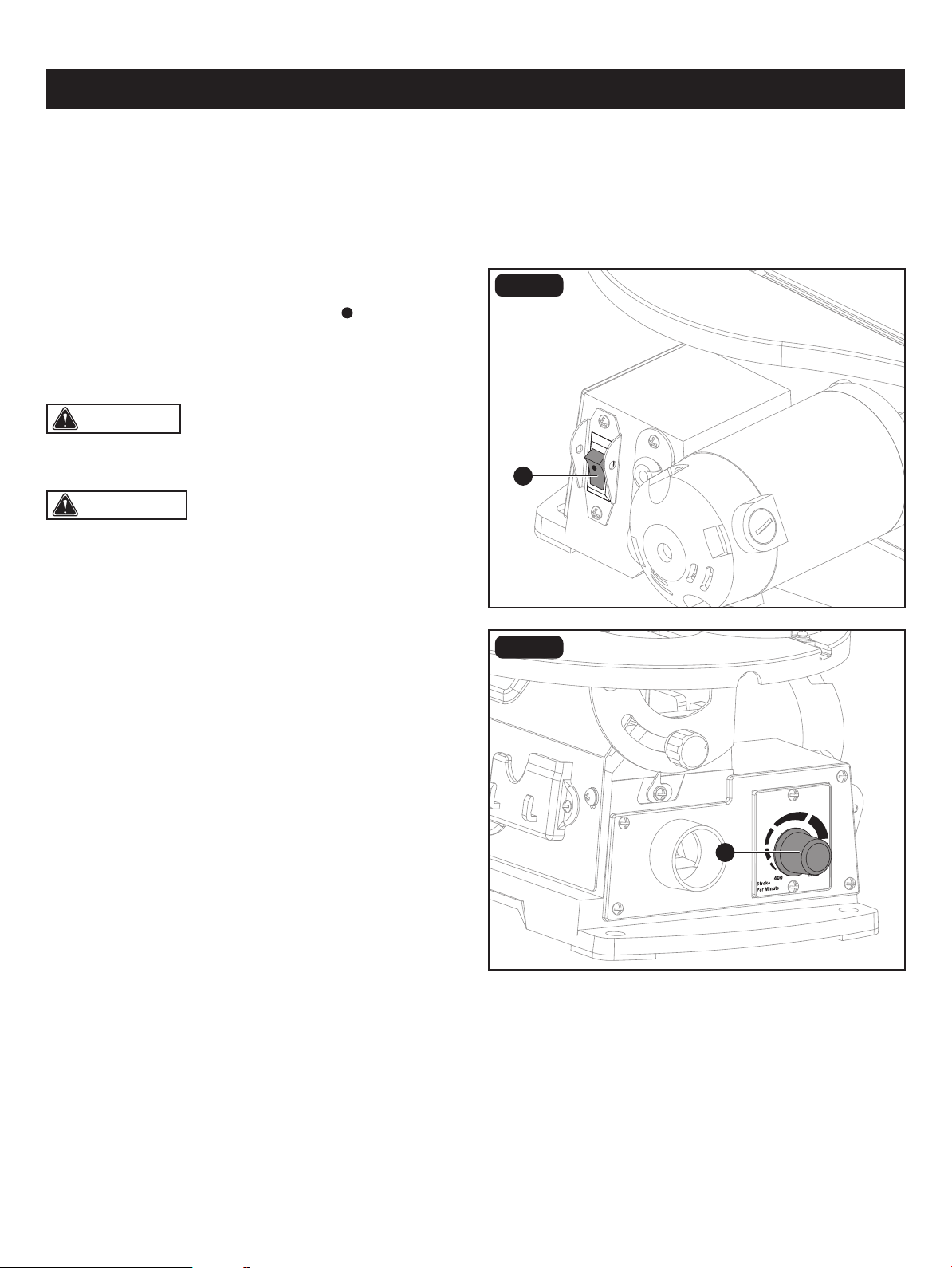
ON/OFF SWITCH (Fig. 11)
• To turn the saw On, press the button “ ” on the on/off
switch (A).
• To turn the saw Off, press the lower button on the on/off
switch (A).
FIG. 12
USING VARIABLE SPEED (Fig. 12)
You scroll saw has a variable speed knob (A). By turning the
knob, the variable speed control may be adjusted from the
high speed of approximately 1600 RPM to the low speed
of approximately 400 RPM. Suggested speeds are referred
to the section “Blade Selection”.
• Turn the variable speed knob (A) to adjust the blade speed
to the desired setting. Turning the knob clockwise increases
speed. Turning it counterclockwise reduces speed.
WARNING: To avoid possible serious injury from accidental starting, always turn the saw off, and unplug the saw
from power source before removing or replacing the blade.
WARNING: To prevent serious personal injury, never leave the saw unattended until the blade has come to a
complete stop.
FIG. 13
SETTING THE WORK TABLE ANGLE
(FIG. 13)
• Undo the bevel lock knob (A).
• Set the angle by tilting the work table (B).
• Fix the angle by tightening the bevel lock knob (A).
FIG. 14
SETTING THE SAWING ANGLE (FIG. 14)
• Set the angle by loosening the lock knob (A) on miter
gauge (B). The angle can be read from the scale.
• Fix the angle by tightening the lock knob (A).
SCROLL CUTTING
For general type scroll cutting, follow the pattern lines by pushing and turning the workpiece at the same time. Do not try
to turn the workpiece while engaged in the blade without pushing it – the workpiece could bind or twist the blade.
B
A
B
A
OPERATION
Page 21
WARNING: To avoid possible, serious personal
injury, do not cut more than one loose piece of material at
a time.
WARNING: Do not allow familiarity with your saw
to make you careless. Remember that a careless fraction
of a second is sufcient to inict severe injury.
B
A
Page 22
FIG. 15
OPERATION
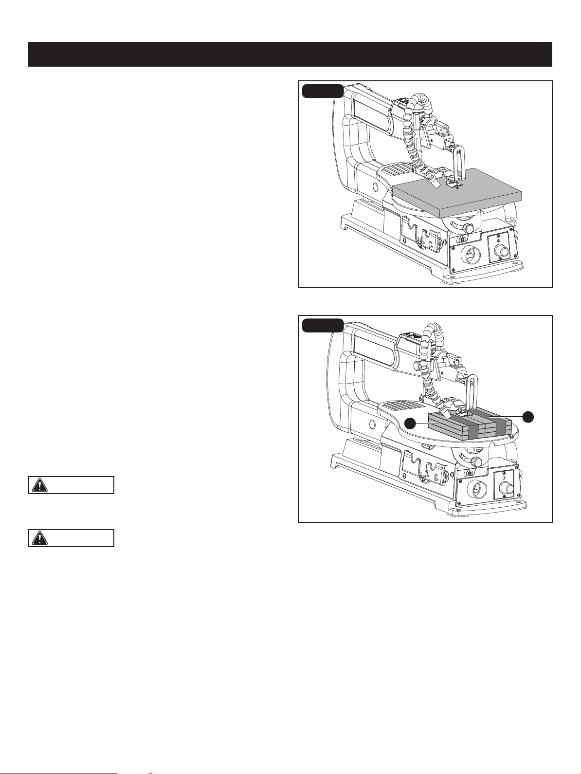
INTERIOR SCROLL CUTTING (Fig. 15)
• One feature of a scroll saw is that it can be used to make
scroll cuts on the interior of a workpiece without breaking
or cutting through the edge or perimeter of the board.
• To make interior cuts in the workpiece, remove the scroll
saw blade as explained in the section on blade removal
and installation on page 16-17.
• Drill a 1/4 in. (6 mm) hole in the workpiece.
• Place the workpiece on the work table with the drilled hole
over the access hole in the table.
• Install blade through the hole in the workpiece; adjust the
drop foot and blade tension.
• When nished making the interior scroll cuts, simply
remove the blade from the blade holders as described in
the section on blade removal and installation, page 16-17,
and remove the workpiece from the work table.
FIG. 16
STACK CUTTING (Fig. 16)
After becoming well acquainted with your saw through
practice and experience, you may wish to try stack cutting.
Stack cutting may be used when several identical shapes
need to be cut. Several pieces of wood may be stacked on
top and secured to each other before cutting. The wood
pieces (A) may be joined together by placing double sided
tape (B) between each piece or by wrapping masking tape
around the corners or ends of the stacked wood. You must
attach the stacked pieces of wood to each other so they
will move on the table as a single piece of material.
WARNING: To ensure safety and reliability, all repairs should be performed by a qualied. service technician.
Page 23
B
B
A
A
CLEANING
• Keep your scroll saw clean.
• After cleaning the table top initially, apply a thin coat of automobile type (paste) wax to the table top so the wood slides
easily while cutting.
• Do not allow pitch to accumulate on the saw table. Clean with gum and pitch remover.
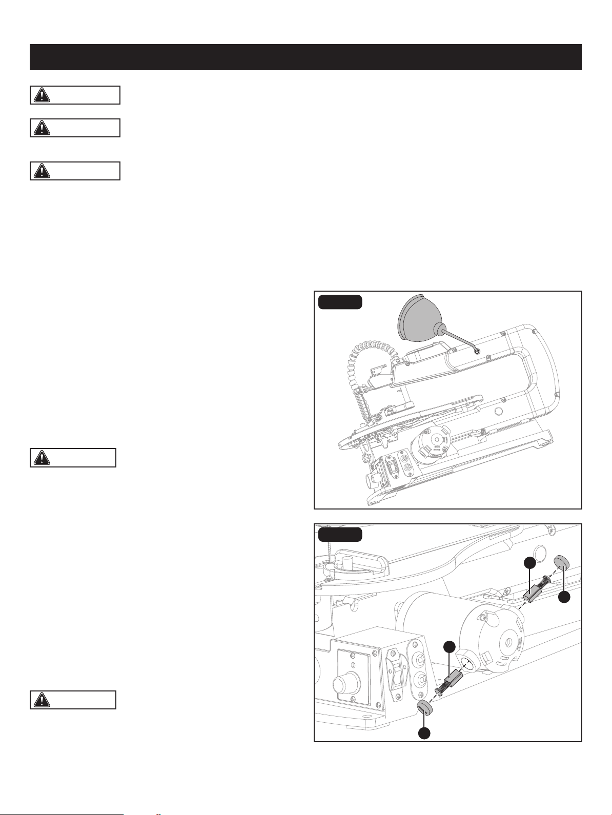
LUBRICATION (Fig. 17)
Lubricate the arm bearings (one on each side of the saw)
after the rst 10 hours of use. Oil after every 50 hours of use
or whenever there is a squeak coming from the bearings.
• Carefully place the saw on its side, as shown in Figure 17.
Remove the rubber cap from the upper and the lower arm
of the saw.
• Squirt a few drops of SAE20 oil around the shaft end and
arm bearings. Let oil soak in overnight, remaining in this
position.
FIG. 17
BRUSH REPLACEMENT (Fig. 18)
• Your saw has externally accessible motor brush assemblies
that should be checked after 50 hours of use for wear.
When one of the two brushes becomes worn to 1/16"
(2 mm) in length, replace both brushes.
• Unplug the saw from the power source.
• Loosen and remove the two brush caps (A) using a
screwdriver.
• Pull out each brush (B). Inspect the brush and replace if
necessary. Replace both brushes even if only one is
damaged.
• Position the brushes in the motor. Tighten the brush caps snugly. Do not overtighten.
FIG. 18
MAINTENANCE
CAUTION: You lubricate the bearings on the other
side of the saw in this same manner.
CAUTION: After inspecting the brushes, be sure to
re-install the brushes in the same position that they were in
if you are not installing new ones.
WARNING: When servicing, use only identical replacement parts. The use of any other parts may create a hazard
or cause damage to the tool.
WARNING: Always switch the product off, disconnect it from the power supply and let the product cool down
before performing inspection, maintenance, lubrication and cleaning work!
• Run the saw for approximately ve to ten minutes to allow the brushes to "seat" themselves. If the brushes are not seated
correctly, the electric brake may not function correctly and could damage the motor. While the brushes are seating,
some sparking may be noticed in the motor. This is normal for new brushes.
FIG. 19
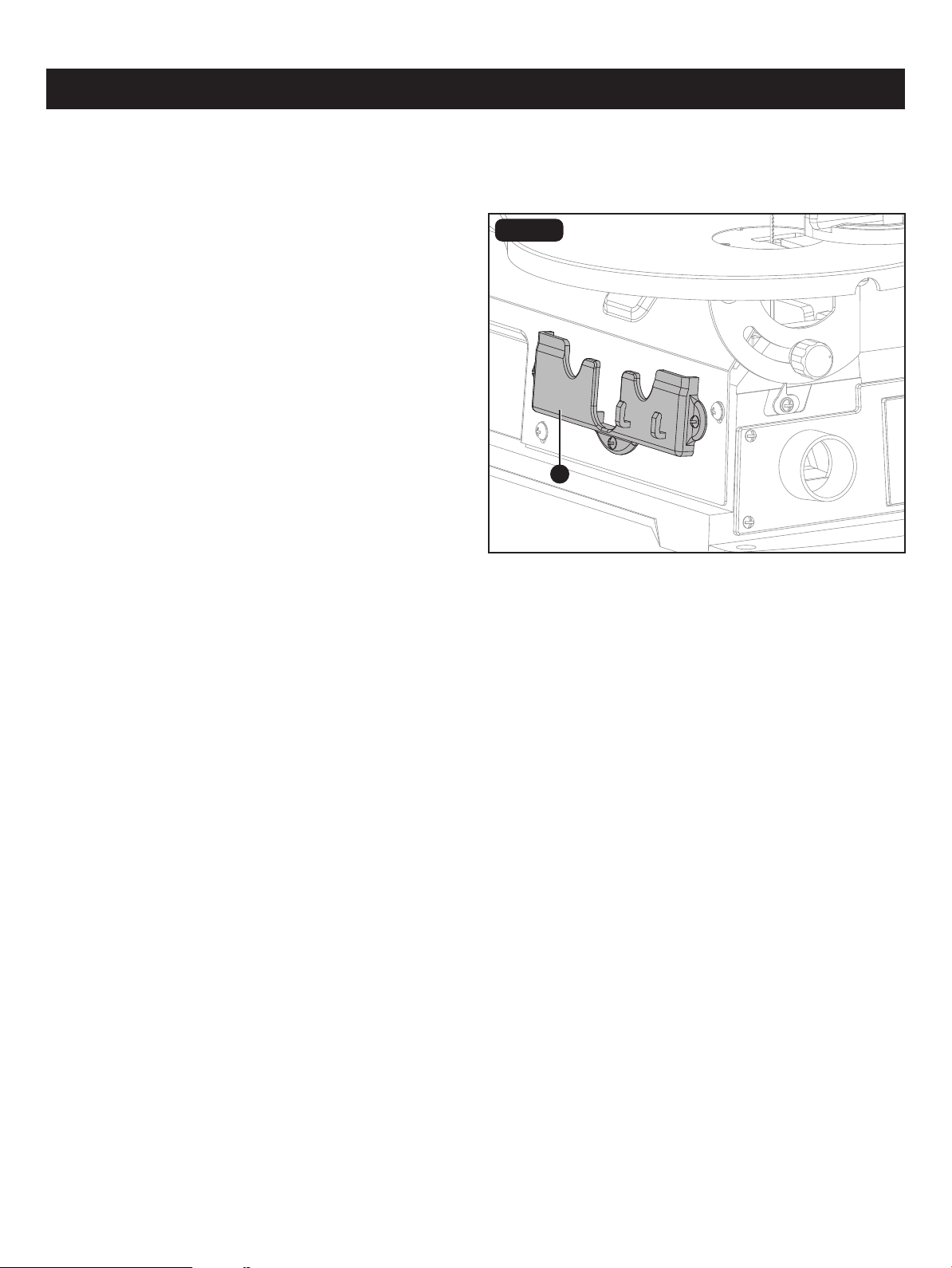
STORAGE COMPARTMENT (Fig. 19)
The scroll saw has the storage compartment (A) that is
located under the left side of the work table. It can be used
for storage of small accessories, such as saw blades or hex
keys.
C
MAINTENANCE
Page 24
A

TROUBLESHOOTING
Motor will not run. • Have worn parts replaced before using
scroll saw again. Have the proper outlet
installed by a qualied electrician.
• Do not attempt any repair. Have repaired
by a qualied service technician.
• Problem with ON/OFF switch, power
cord, or outlet.
• Motor defective.
Blades breaking. • Adjust blade tension.
• Reduce feed rate or replace blade.
• Use narrow blades for thin wood, wider
blades for thicker wood.
• Avoid side pressure on blade.
• Incorrect tension.
• Overworked (worn out) blade.
• Wrong blade being used.
• Twisting blade in wood.
PROBLEM PROBLEM CAUSE CORRECTIVE ACTION
Vibration (there is always
some vibration when the saw
is running).
• See proper mounting instructions.
• Replace plywood workbench surface
with solid lumber surface.
• Tighten table bevel lock knob.
• Tighten motor mount screws.
• Improper mounting of saw.
• Mounting surface.
• Loose table or table resting against
motor.
• Loose motor mounting.
Blade runout. • Increase blade tension.
• Renew blade and correctly tension.
• Insufcient blade tension.
• Dull blade causing excessive force to be
used at workpiece.
Page 25
Page 26
REPLACEMENT PARTS LIST
A
B
C
D
E
A 24037260001
24037260002
24037260004
Lock Knob
Miter Gauge
PART DESCRIPTION PART#
D
B
24037260003Angel GaugeC
24037260005E
Table Insert
2.5mm Hex Key
PART DESCRIPTION PART#
For questions / comments, technical assistance or repair parts - Please call toll free at: 1-877-684-8912 (Monday - Friday
8am - 6pm EST.)
FIG. 20

Page 27
Distributed by: Menard, Inc., Eau Claire, WI 54703
For questions / comments, technical assistance or repair parts – Please Call Toll
Free at: 1-877-684-8912 (Monday - Friday 8am – 6pm EST.)
SAVE YOUR RECEIPTS
THIS WARRANTY IS VOID WITHOUT THEM
16" Scroll Saw
WARRANTY
TWO-YEAR LIMITED WARRANTY:
If, during normal use, this PERFORMAX™ power tool breaks or fails due to a defect
in material or workmanship within two years from the date of original purchase,
simply bring this tool with the original sales receipt back to your nearest Menards™
retail store. At its discretion, PERFORMAX™ agrees to have the tool or any defective
part(s) repaired or replaced with the same or similar PERFORMAX™ product or part
free of charge, within the stated warranty period, when returned by the original
purchaser with original sales receipt. This warranty; (1) excludes expendable parts;
(2) shall be void if this tool is used for commercial and/or rental purposes; and (3)
does not cover any losses, injuries to persons/property or costs. This warranty does
give you specic legal rights and you may have other rights, which vary from state
to state.