
TACKLife
USER MANUAL
SCROLL SAW
TACKLife
Model: TLSS01A
6
1
7
5
4
3
2
1
13
12
11
10
9
8
2
20
3
4
F
B E
C
D
E
5
G
A
21
22
14
15
17
19
18
16
24
1
15
23
5
25
26
11
13
6
3
4
7
25
26
3
4
23
5
2
1
8
2
27
1
5
9
28
13
10
28
29
23
30
31
14
31
12
14
34
15
33
32
33
6
14
15
15
18
34
34
37
14
35
9
36
10
16
17
23
38
24
39
40
41
47
42
43
44
45
46
48
49
50
51
52
54
7
19
52
55
56
57

Tableof contents: Page:
1. Explanation of the symbols on the equipment................................................................................................ 2
2. Introduction...................................................................................................................................................... 3
3. Device and accessories description (fig. 1-15).................................................................................................3
4. Intended use.....................................................................................................................................................4
5. Safety information.............................................................................................................................................4
6. Technical data...................................................................................................................................................6
7. Before starting the machine..............................................................................................................................6
8. Assembly...........................................................................................................................................................7
9. Operation..........................................................................................................................................................8
10. Electrical connection ........................................................................................................................................9
11. Transport...........................................................................................................................................................9
12. Cleaning, maintenance, storage and ordering of spare parts...........................................................................10
13. Storage..............................................................................................................................................................10
14. Disposal and recycling.......................................................................................................................................10
15. Troubleshooting..................................................................................................................................................11
16. Warranty certificate.............................................................................................................................................12
17. Declaration of conformity....................................................................................................................................52
1.
Explanation of the symbols on the equipment
2. Introduction
Dear Customer
we hope your new tool brings you much enjoyment and success.
NOTE:
According to the applicable product liability laws, the manufacturer of the device does not assume
liability for damages to the product or damages caused by the product that occurs due to:
Improper handling,
Non-compliance of the operating instructions,
Repairs by third parties, not by authorized service technicians,
Installation and replacement of non-original spare parts,
Application other than specified,
A breakdown of the electrical system that occurs due to the non-compliance of the electric regulations and VDE
regula
tions 0100, DIN 57113 / VDE0113.
Warning! Read the operating instructions to reduce the risk of injury!
Wear safety goggles. Sparks generated during work or splinters, chips and dust emitted by
the equipment can cause loss of sight.
Wearsafetygoggles.Sparksgeneratedduringworkorsplinters,chipsanddustemittedby
the equipment can cause loss of sight.
Wear ear-muffs. The impact of noise can cause damage to hearing.
Important. Risk of injury. Never reach into the running saw blade.
Switch for changing between manual controls (M) and foot pedal controls (F)
(see 10.4
and 10.5)

We recommend:
Read through the complete text in the operating instructions be- fore installing and commissioning the device.
The operating instructions are intended to help the user to be- come familiar with the machine and take advantage
of its ap- plication possibilities in accordance with the recommendations. The operating instructions contain
important information on how to operate the machine safely, professionally and econom- ically, how to avoid
danger, costly repairs, reduce downtimes and how to increase reliability and service life of the machine. In addition
to the safety regulations in the operating instruc- tions, you have to meet the applicable regulations that apply for
the operation of the machine in your country.
Keep the operating instructions package with the machine at all times and store it in a plastic cover to protect it
from dirt and moisture. Read the instruction manual each time before operat- ing the machine and carefully follow
its information.
The machine can only be operated by persons who were in- structed concerning the operation of the machine and
who are informed about the associated dangers. The minimum age re- quirement must be complied with.
In addition to the safety instructions contained in this operating manual and the specific regulations of your country,
the techni- cal rules generally accepted for the operation of machines of the same type must be observed.
We accept no liability for damage or accidents which arise due to non-observance of these instructions and the
safety in- formation.
3.
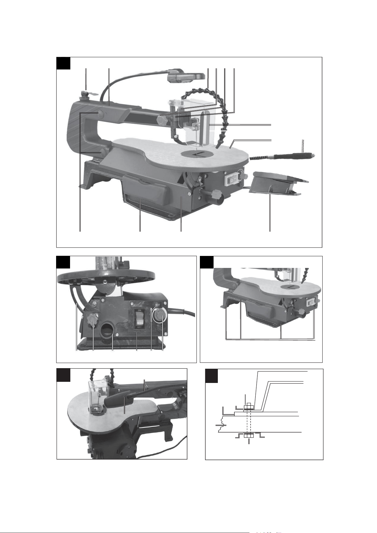
Device and accessories description (fig. 1-17)
1
Blow-off device
20
Assembly points
39
Allen key 2
2
Mounting (Blow-off device)
21
Work lamp
40
hex key
3
Knurled screw
22
ON/OFF switch work lamp
41
Small wrench
4
Holder (Saw blade guard)
23
Saw blade 1
42
Spiral Cutting Bit 6mm
5
Saw blade guard
24
Allen key,3mm
43
Spiral Cutting Bit 3.2mm x4
6
Saw table
25
Retaining device
44
Grinding wheel x3
7
Flexible Driver
26
Screw (retaining device)
45
Drill bits x2
8
Foot pedal
27
Table insert
46
Spiral Cutting Bit
9
Cover, left
28
Saw blade holder, top
47
Spiral Sanding band bit
12.7mm
10
Storage box
29
Uppersaw blade clampingscrew
48
Sanding band 12.7mm x6
11
Bearings
30
Lower saw blade clamping screw
49
Spiral Sanding band bit 6.3mm
12
Tightening lever
31
Saw blade holder, bottom
50
Sanding band 6.3mm x6
13
Arm
32
Angle (not included in the scope of
delivery)
51
Cut off wheel x 5
14
Graduated scale
33
Screw (degree scale)
52
15
Locking lever
34
Pointer
53
16
Suction connection & suction adapter
35
Screw (left cover)
54
17
ON/OFF switch
36
Screw (left cover)
55
18
Operating mode selection switch
37
Fine-wire fuse
19
Speed regulator
38
Saw blade 2

4.
Intended use
The fretsaw was designed to cut square-edged timber or other workpieces such as Plexiglas, glass
fiber reinforced plastic, foam, rubber, leather, and cork. Do not use this saw to cut round materials.
Round materials can easily become jammed. Risk of injury! Parts can be catapulted!
The equipment may only be used for the tasks it is designed to handle. Any other use is deemed to be
a case of misuse. The user/operator and not the manufacturer will be liable for any damage or injuries
of any kind caused as a result of this.
Please note that our equipment has not been designed for use in commercial, trade or industrial
applications. Our warranty will be voided if the equipment is used in commercial, trade or industrial
businesses or for equivalent purposes.
The equipment is to be operated only with suitable saw blades.
To use the equipment properly you must also observe the
safety information, the assembly instructions and the
operat-
ing instructions to be found in this manual.
All persons who use and service the equipment have to be
acquainted with these operating instructions and
must be in-
formed about the equipment’s potential hazards.
It is also imperative to observe the accident prevention regu-
lations in force in your area.
The same applies for the general rules of health and safety at work.
The manufacturer will not be liable for any changes made to the equipment nor for any damage resulting
from such changes.
Residual risks
Even if you use this electric power tool in accord- ance to instructions, certain residual risks
cannot be eliminated. The following hazards may arise in connection with the equipment’s
construction and layout:
Lung damage if no suitable protective dust mask is applied
Damage to hearing if no suitable ear protection is applied
Contact with the blade in the uncovered cutting zone
Injuries (cuts) when changing the blade
Crushed fingers
Kickback
Tilting of the workpiece due to inadequate support
Touching the blade
Catapulting of pieces of timber and workpieces
5. Safety information
5.1 General safety information on electric power tools
CAUTION
The following basic safety measures must be observed when using electric tools for protection against electric shock, and
the
risk of injury and fire.
Read all these notices before using the electric tool and store
the safety instructions well for later reference.
Maintenance and service
1. Regular cleaning, maintenance, and lubrication.
Pull out the mains plug before making any settings,
service or
repair work.
2. Only have your device repaired by qualified specialists and only with original spare parts. This
ensures that safety of the device is maintained.

Safe work
1. Keep your work area tidy
- Disorder in the work area can lead to accidents.
2. Check the ambient conditions
- Do not expose electric tools to rain.
- Never use electric power tools in damp or wet locations.
- Make sure that the work area is well-illuminated.
- Do not use electric tools where there is a risk of fire or explosion.
3. Protect yourself against electric shocks
- Avoid physical contact with earthed parts (e.g. pipes, radiators, electric ranges, cooling devices).
4. Keep other persons away
- Do not allow other persons, especially children, to touch the electric tool or the cable. Keep them away
from your work area.
5. Securely store unused electric tools
- Unused electric tools should be stored in a dry, el- evated or closed location out of the reach of
children.
6. Do not overload your electric tool
- They will work better and more safely within their speci- fied capacity range.
7. Use the right tools
- Do not use low-output electric tools for heavy work.
- Do not use the electric tool for purposes for which it is not intended. For example, do not use
hand-held circular saws for the cutting of branches or logs.
8. Wear suitable clothing
- Do not wear wide clothing or jewellery, which can become entangled in moving parts.
- When working outdoors, anti-slip footwear is recommended.
- Wear a hair net if you have long hair.
9. Use personal safety equipment.
- Wear safety goggles.
- Use a dust mask when working on dusty jobs.
10. Connect up the dust extraction system
- If connections for dust extraction and a collecting de- vice are present, make sure that they are
connected and used properly.
11. Do not use the cable for purposes for which it is not intended
- Do not use the cable to pull the plug out of the socket. Protect the cable from heat, oil and sharp
edges.
12. Secure the workpiece
- Use the clamping devices or a vice to hold the workpiece in place. In this manner, it is held more
securely than with your hand.
13. Avoid abnormal working postures.
- Make sure you stand squarely and keep your balance at all times.
14. Take care of your tools
- Keep cutting tools sharp and clean in order to be able to work better and more safely.
- Follow the instructions for lubrication and for tool re- placement.
- Check the connection cable of the electric tool regularly and have it replaced by a recognised
specialist when damaged.
- Check theex tension cable regularly and replace it if damaged.
- Keep handles dry and free from oil and grease.
15. Pull the connector out of the socket
- When the electric tool is not in use or prior to maintenance and when replacing tools such as saw
blades, bits, milling heads.

16. Always remove keys and wrenches after use
- Always check that keys, wrenches and other adjusting tools have been removed before you switch on
the equipment.
17. Avoid unintentional starting
- Make sure that the switch is turned off when connecting the tool to the power supply.
18. Use extension cables for outdoors
- Check that it is approved for outdoor duty and is marked accordingly.
19. Be alert at all times
- Watch what you are doing. Use common sense when working. Never use the tool when you are
distracted.
20. Check the electric tool for potential damage
- Protective devices or other parts with minor damage must be carefully inspected to ensure that they
function correctly and as intended prior to continued use of the electric tool.
- Check whether the moving parts function faultlessly and do not jam or whether parts are damaged. All
parts must be correctly mounted and all conditions must be fulfilled to ensure fault-free operation of
the electric tool.
- Damaged protective devices and parts must be properly repaired or replaced by a recognised
specialist workshop, insofar as nothing different is specified in the user manual.
- Damaged switches have to be replaced by a customer service workshop.
- Do not use any electric tool on which the switch cannot be switched on and off.
21. ATTENTION
- The use of other insertion tools and other accessories can entail a danger of injury.
22. Have your electric tool repaired by a qualified electrician
- This electric tool conforms to the applicable safety regulations. Repairs may only be performed by an
electrician using original spare parts. Otherwise accidents can occur.
-
WARNING
This electric tool generates an electromagnetic field during operation. This field can impair active or passive medical
implants under certain conditions. In order to prevent the risk of serious or deadly injuries, we recommend that persons
with medical implants consult with their physician and the manufacturer of the medical implant prior to operating the
electric tool.
5.2 Additional safety instructions
Switch the machine off immediately and pull the power plug in an emergency.
Follow all these safety instructions before and while working with the saw.
Do not use this saw to cut fire wood.
Do not use this saw to cross-cut round wood without a suit- able holding device.
The machine is equipped with a safety switch to prevent it from being switched on again accidentally after a
power failure.
If you need to use an extension cable, make sure its conductor cross-section is big enough for the saw’s power
consumption. Minimum cross-section 1,5 mm2.
If you use a cable reel, the complete cable must be pulled off the reel.
Persons working on the machine should not be distracted.
After you have switched off the motor, never slow down the saw blade by applying pressure to its side.
Only fit blades which are well sharpened and have no cracks or deformations.
Faulty saw blades must be replaced immediately.
Never use saw blades which do not comply with the data specified in this manual.
It is imperative to make sure that all devices which cover the saw blade are in good working order.
Never dismantle the machine’s safety devices or render them inoperative.
Damaged or faulty safety devices have to be replaced immediately.
Never cut workpieces which are too small to hold securely in your hand.
Never load the machine so much that it cuts out.

Always press the workpiece firmly against the saw table.
Never remove loose splinters, chips or jammed pieces of wood when the saw blade is running.
Switch the machine off to rectify faults at the blocked plug-in tool. - Pull the power plug- Remove the blockage.
Important! Risk of injury from saw blade! Wear gloves. Carry out a trial run without a workpiece. Ensure that no
unusual noise or vibration occurs. Should this be the case, switch the unit off and contact the manufacturer.
Carry out retooling work, adjustments, measurements and cleaning jobs only when the motor is switched off. -
Pull the power plug.
Before switching on, make sure that all keys and wrenches have been removed from the tool.
Switch off the motor and pull the power plug before you leave the workplace.
Electrical installation work, repairs and maintenance may only be carried out by persons who have been
specially trained.
Refit all guards and safety devices immediately after you have completed any repairs or maintenance work.
Be sure to observe the safety information and operating and maintenance instructions issued by the
manufacturer, as well as the dimensions listed in the Technical Data.
It is imperative to observe the accident prevention regulations in force in your area as well as all other generally
recognized rules of safety.
Note the information published by your professional associations (VBG 7).
The saw is intended to be used indoors only.
Workpieces that are smaller than the saw blade guard can cause injuries to the hands or fingers. Use suitable
aids!
Avoid cramped hand positions when guiding in the work- piece and avoid positions in which slipping could lead
to your hand making direct contact with the saw blade.
Always fit the saw blade with the teeth facing in the direction of the sawing table.
Always set the correct blade tension to prevent the saw blades from jerking.
Be especially careful when cutting material with irregular cut profiles.
Exercise particular caution when cutting round objects such as rods and pipes. These can roll down into the saw
blade and cause the teeth to catch. Use a wedge to brace such work- pieces.
The teeth can become caught in the kerf when the workpiece is pulled back, especially if sawings have filled in
(blocked) the kerf. In this case, you should switch the saw off, pull the power plug, clear the kerf with a wedge,
and remove the workpiece.
Never leave the work area without having already switched the saw off. Wait until the saw stops moving
completely.
Do not position, join, or construct any parts on the work table while the saw is running.
Only switch the saw on after you have removed any remain- ing material and tools from the work table. Leave
only the workpiece to be machined and any aids (e.g. wedges) on the work table.
Always wear safety goggles!
Keep your fingers at a safe distance from the saw blade.
Carefully guide the workpiece and keep it steady at all times.
Never leave the work area without having already switched the saw off.
Do not let your familiarity with the saw allow you to be care- less. Carelessness can lead to severe injuries within
a fraction of a second.
Working position is always laterally of the saw blade.
Do not lose this safety information.

6. Technical data
Mains voltage............................ .....120 V/60 Hz
Power input.......
..........................
...80 Watt (S1*)
.......................................................120 Watt (S6 30%**)
Stroke rate...................................370-1440 min
-1
Protection type
..................................
...
P 20
Stroke..........................................12 mm
Rotate of Flexible Driver............. 2400-4500rpm
Base area....................................630 x 295 mm
Tilting range of table.....................
0°
bis
45°
nach links
Table size.....................................415 x 255 mm
Length of saw blade approx.........134 mm
Reach..........................................406 mm
Max. cutting height at 90°............50 mm
Max. cutting height at 45°............22 mm
Minimum size work piece w x h....100 x 22 mm
Maximum size work piece w x h...400 x 50 mm
Weight.........................................13.2 kg
*Operating mode S1:
Continuous operation at constant load
**Operating mode S6 30%:
Continuous operation with idling (cycle time 10 minutes). To ensure that the motor does not become
excessively hot, it may only be operated for 30% of the cycle at the specified rating and must then be
allowed to idle for 70% of the cycle.
Noise emission values Sound
Sound values were measured in accordance with EN 61029.
Wear ear-muffs.
The impact of noise can cause damage to hearing.
Sound pressure level LpA................................................................................................... 66,9 dB(A)
Uncertainty KpA........................................................................................................................3 dB(A)
Sound power level LWA.......................................................................................................79,9 dB(A)
Uncertainty KWA.......................................................................................................................3 dB(A)
The quoted values are emission values and not necessarily reli- able workplace values. Although there
is a correlation between emission and imission levels it is impossible to draw any certain conclusions
as to the need for additional precautions.
Factors with a potential influence on the actual immission level at the workplace include the duration of
impact, the type of room, and other sources of noise etc., e. g. the number of ma- chines and other
neighbouring operations.
Reliable workplace values may also vary from country to coun- try. With this information the user
should at least be able to make a better assessment of the dangers and risks involved.
Limit the noise level to a minimum!
Use only equipment that is in perfect condition.
Maintain and clean the equipment regularly.

Adopt your way of working to the equipment.
Do not overload the equipment.
Have the equipment checked if necessary.
Switch off the equipment when not in use.
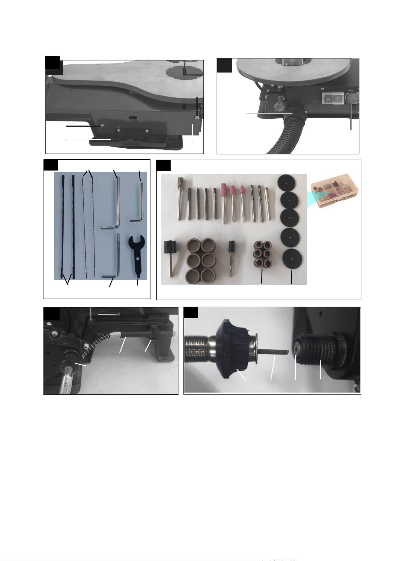
Suitable saw blades
All industry-standard saw blades with a minimum length of 127 mm with and without a pin may be
used.
7. Before starting the machine
7.1 Unpacking
Open the packaging and remove the device carefully.
Remove the packaging material as well as the packaging and transport bracing (if available).
Check that the delivery is complete.
Check the device and accessory parts for transport damage.
If possible, store the packaging until the warranty period has expired.
ATTENTION
The device and packaging materials are not toys! Children must not be allowed to play with plastic
bags, film and small parts! There is a risk of swallowing and suffocation.
7.2 General notes
All covers and safety devices have to be properly fitted be- fore the equipment is switched on.
It must be possible for the blade to run freely.
When working with wood that has been processed before, watch out for foreign bodies such as nails or screws,
etc.
Before you actuate the On/Off switch, make sure that the saw blade is correctly fitted and that the equipment’s
moving parts run smoothly.
Check that the voltage on the rating plate is the same as your supply voltage before you connect the equipment
to the power supply.
Only ever connect the equipment to a properly installed shock-proof socket which is protected by a 10A fuse as a
minimum.
WARNING
Danger of injury! Disconnect the mains plug on the scroll saw before all assembly work.
1. The length of the screws to be used varies, depending on the thickness of the table top.
2. Mark the drill holes. Use the fretsaw as a template for this purpose.
3. Drill 4 holes with a diameter of 8 mm into the work table and the rubber base.
4. Screw the scroll saw onto the workbench with the hex- agonal bolt (G) through the assembly points (fig. 3 pos20)
in the following sequence (fig. 5):
A Fretsaw
B Rubber base
C Work table
D Flat gasket
E Washer
F Hex nut
5. Tighten the hexagonal nut (F) first

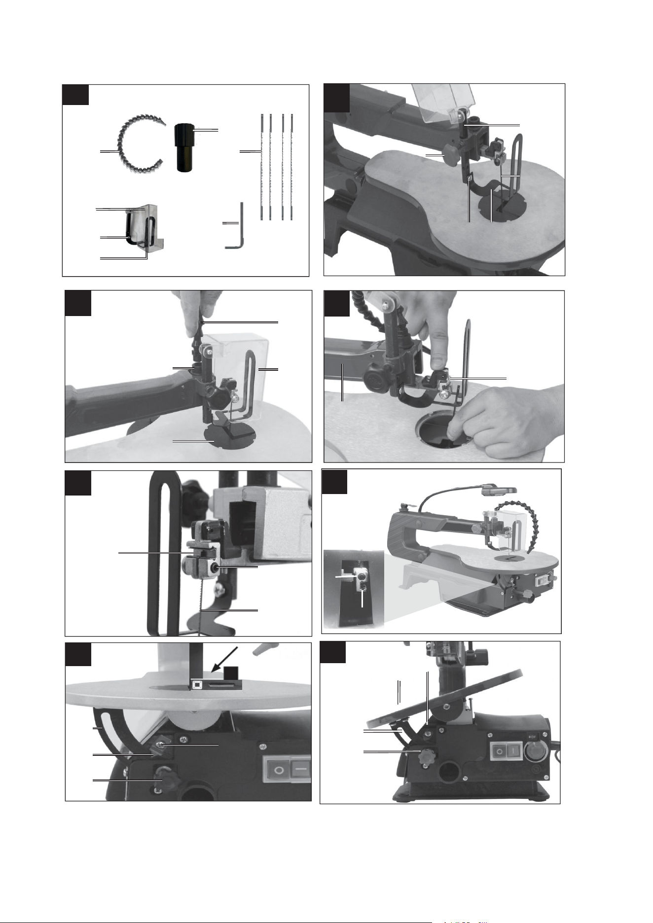
8. Assembly
WARNING
Danger of injury! Disconnect the mains plug on the scroll saw before all assembly work.
8.1 Installing the depressor (fig. 6, 7)
NOTE:
Before assembling the depressor (25), the saw blade pre-in- stalled at the factory (23) must be
removed (see 9.3).
1
.
Remove the saw blade (23) as described in 9.3.
2
.
Remove the depressor (25) from the saw blade guard
3
.
(5) by loosening the screw (26) completely (see fig. 6).
4
.
Insert the holder (4) into the opening (see fig. 7).
5
.
Fasten the holder (4) with the knurled screw (3).
6
.
Install the depressor (25). Insert the screw (26) into the holder (4) and fasten it.
7
.
Insert the saw blade (23) again as described in 9.3.
8.
Ensure that the depressor (25) does not contact the saw blade (23).
The depressor (25) must always be adjusted according to the workpiece height. However, the
workpiece should not be clamped, but should rather be able to move freely.
The depressor (25) is used to lock the workpiece so that it cannot swing upwards, which would destroy
the saw blade (23).
8.2 Installing the blow-off device (fig. 8)
1
.
Ensure that the saw blade guard (5) folded down.
2
.
Screw the blow-off device (1) clockwise onto the holder(2) as described in fig. 8.
8.3 Changing the saw blade (fig. 1, 8-11)
IMPORTANT
To avoid injuries attributed to inadvertent startup: Before removing or replacing the saw blade, al- ways
press “0“ and remove the mains plug from the socket.
8.3.1 Removing the saw blade without pins (optional)
1. To remove the saw blade (23) , lift the table insert (27) upwards.
2. First, release the tension by flipping the tension lever (12) upwards. Continue reducing the tension by turning
clock- wise as required.
3. Press the support (13) down lightly (see fig. 9).
4. Then loosen the upper saw blade clamping lever (29), followed by the lower saw blade clamping lever (30) using
the Allen key (24)
8.3.2 Inserting the saw blade without pins (optional)
The teeth of the saw blade must always point downwards.
1. First, secure the saw blade (23) in the lower saw blade mounting (31). To secure the saw blade (21), tighten the
lower saw blade clamping screw (30) using the Allen key (24).
2. Press the support (13) down lightly. Fasten the other end of the saw blade (23) in the top saw blade holder (28)
(see fig. 9).
3. Fix the saw blade (23) with the upper blade clamping screw (29) (see fig. 10).
4. Tighten the saw blade (23) with the clamping lever (12), by pressing it down again. Check the tension of the saw
blade (23). If the tension is insufficient, it can be increased by turning the lever clockwise. First release the
clamping lever (12).
5.
Put the table insert (27) back.

8.3.3 Removing the saw blade with pins
1. To remove the saw blade (23), lift the table insert (27) upwards.
2. First, release the tension by flipping the tension lever (12) upwards. Continue reducing the tension by turning
clock- wise as required.
3. Press the support (13) down lightly (see fig. 9).
4. Pull the saw blade from the upper and lower saw blade mounting (28/31).
8.3.4 Inserting the saw blade with pins
The teeth of the saw blade must always point downwards.
1. Insert one end of the saw blade (23) through the drilled hole in the table. Insert the pins of the saw blade (23) into
the corresponding recesses of the top and bottom saw blade holder (28/31).
2. First insert the saw blade (23), in the lower blade holder (31).
3. Press the support (13) down lightly (see fig. 9).
4. Check the position of the saw blade pins in the saw blade mountings (28/31).
5. Tighten the saw blade (23) with the clamping lever (12), by pressing it down again. Check the tension of the saw
blade (23). If the tension is insufficient, it can be increased by turning the lever clockwise. First release the
clamping lever (27).
NOTE
The left side features a storage box (10), which enables you to stow replacement saw blades and the
hexagon wrench.
8.4 Checking the saw blade tension
WARNING
Check the blade tension regularly and after insert- ing a saw blade.
Tension the saw blade after assembly by pressing down on the tension lever (12).
If the blade tension is too low or too high, proceed as follows:
Fold the tension lever (12) upwards.
Turn the tension lever (12) clockwise to increase the tension and anti-clockwise to reduce it.
Press the tension lever down again to engage the setting.
If the tension is correct, the saw blade should produce a light tone when it is plucked, like a string.
8.5 Calibrating the angle scale (fig. 12)
Important
Check the adjustment of the angular scale before you start working with the unit.
1. To set the saw table, use a 90° bracket (32, not in the scope of delivery). Place this against the saw table and the
saw blade (fig. 12).
2. Loosen the screw (33) and turn the pointer (34) to the 90° marking.
3.
Make a test cut. Check the angle on the workpiece with a protractor. If necessary, readjust the pointer (34).
8.6 Chip extraction (fig. 13)
ATTENTION: Only operate the device with an extraction system.
Connect a suitable chip extraction system (not included in the scope of delivery) to the suction connection (16)
(see fig. 13, sample figure).
ATTENTION: Check and clean the suction channels at regular intervals.
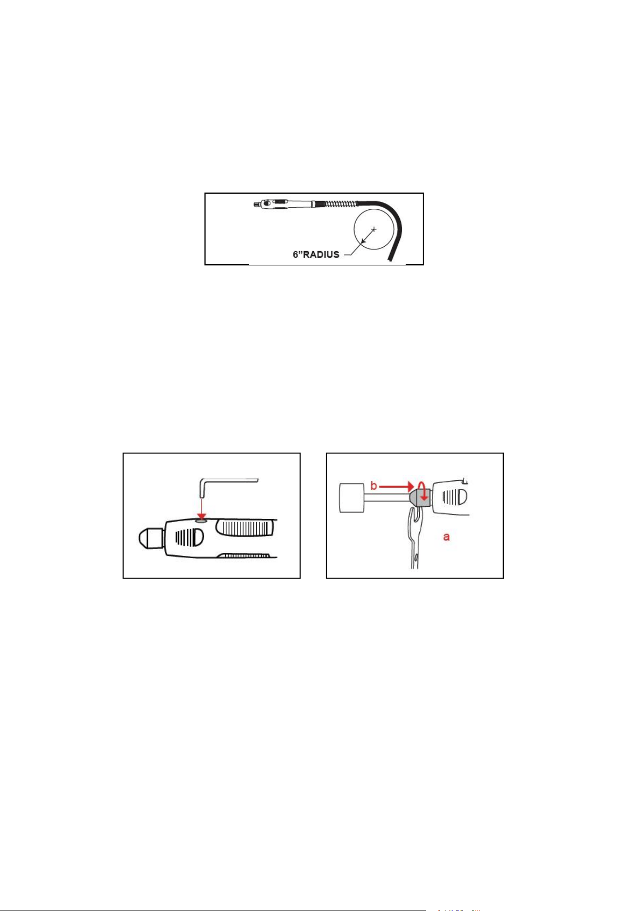
Fig 20
Fig 21
Fig 22
8.7 Flexible Driver Attachment(fig.18, 19)
Safety Rules for Flexible Driver(fig.18, 7)
Do not operate the flexible shaft with a sharp or multiple bends. Ensure that there are no sharp residual
bends or kinks in the Flexible Driver before the operation.
Over bending the shaft can generate excessive heat on the jacket or hand piece and may cause the
Flexible Driver to disengage from the tool.
The minimum recommended bend radius is 6”(fig 20).
Always hold the hand piece firmly in your hands during the start-up. The reaction torque of the motor,
as it accelerates to full speed, can cause the shaft to twist.
Not for use with router bits or other large diameters (1” or larger) bits. Large diameter bits can cause
kickback and loss of control when used with the Flexible Driver.
Do not remove end ferrule while tool is running. The cable will become loose from the jacket and will
uncontrollably whip or lash around.
Installation Diagram of Flexible Driver(fig.16, 17, 18, 19)
1
.
Raise the shaft collar(52) & shake gently until the inner flexible shaft(55) protrudes from fitting collar.
2
.
Insert the inner flexible shaft into the collect(56) then tighten the collar(52) to the nut(57).
3
.
Insert the hex key(fig 16, 40 ) into the hole on the handle(fig 21).
4
.
Loosen collect nut with small wrench(fig 16, 41) then insert shank of accessory(fig 17) into collect.
Tighten collect nut and check all fitting to ensure they are securely fastened.
Directions for use
With small milling cutters / grinding pins: Use a high speed.
With large milling cutters / grinding pins: Use a low speed.
Precision work / engraving: Hold the drive unit like a pen.
Rough work: Hold the drive unit like a hammer.
Tips
Exert only moderate pressure on the workpiece and allow it to be processed at uniform speed.
You will not finish your work sooner by exerting heavy pressure. On the contrary, heavy pressure will cause the
drive unit to slow down or stop and will overload the motor.
For your own safety, use a vise or screw clamp to secure small workpieces.
9. Operation
9.1 General information
The saw does not cut wood automatically. Rather, the opera- tor must push and guide the wood toward the
moving saw blade.
The teeth only cut the wood on the downstroke.
The wood must be slowly pushed and guided toward the saw blade, since the teeth of the blade are very small.
Those who want to use the saw must go through the process of learning how to do so. During this time, a few
blades will invariably break.
When cutting thicker wood, special attention must be paid not to bend or twist the saw blade.
Handling the saw blade properly increases its service life.
9.2 On/off switch (16)
Switching on: Press the “I” button.
Switching off: Press the “0” button.
ATTENTION
The machine is equipped with a safety switch against reactivation if the voltage drops.
If the scroll saw is switched on and the power supply in the mains is interrupted, the scroll saw remains
switched off, even if the power supply is re-established. Press the “I” button to switch it on
9.3 Work lamp operation (fig. 4)
1
.
Switch the machine on as described in 10.2.
2.
The work lamp (21) may not be switched on/and off with the work lamp on/off switch (22).
9.4 Stroke rate controller (fig. 2)
The stroke rate controller (19) allows you to set the stroke rate according to the material to be cut. In
case of soft material, we recommend high stroke rates, while strokes rates should be kept low for hard
material. Turn the stroke rate controller (19) clock- wise to increase the stroke rate. Turning
anti-clockwise lowers the stroke rate.
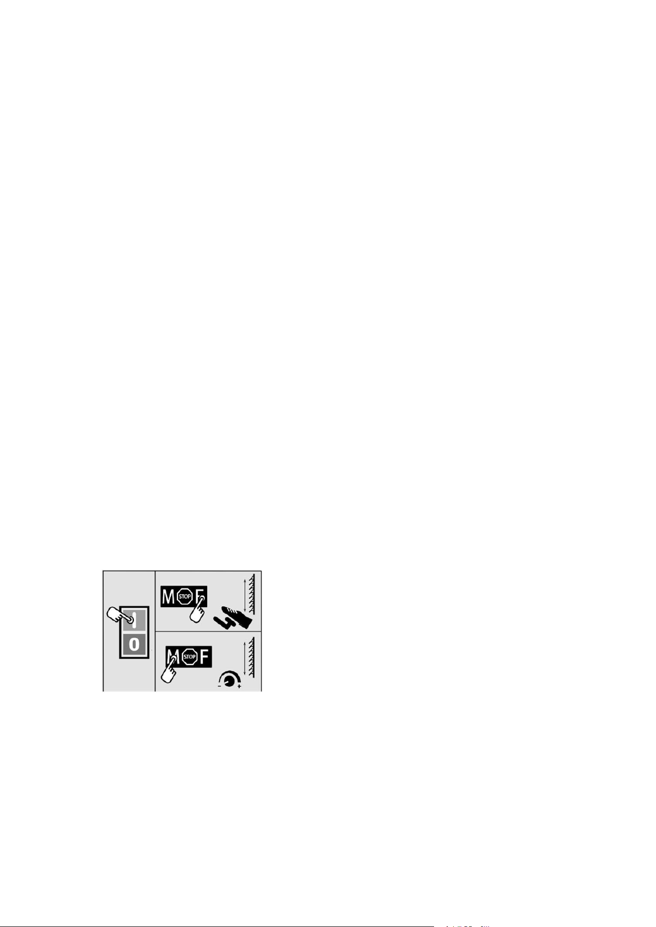
9.5 Operating modes (fig. 1, 2)
The scroll saw is able to be operated manually or via the foot pedal.
9.5.1 Manual controls
1
.
Ensure that the machine is switched on.
2
.
Set the operating mode selection switch (18) to the “M” position to operate the saw manually.
3.
Use the stroke rate controller (19) to set the appropriate stroke rate for the material (see 10.4)
9.5.2 Foot pedal controls
1. Ensure that the machine is switched on.
2. Set the operating mode selection switch (18) to the “F” position to operate the saw via the foot pedal (8).
3. The stroke rate may now be regulated via the foot pedal position. If you depress the foot pedal (8)
completely, you will reach the maximum stroke rate.

CAUTION
When changing from foot pedal controls to manual controls, the machine starts automatically. The
stroke rate corresponds with the stroke rate set on the stroke rate controller (19).
9.6 Making inside cuts
This scroll saw allows inside cuts in workpieces without damaging the outside or the circumference of
the workpiece.
1. Remove the saw blade (23) as described in 9.3.
2. Drill a hole into the workpiece.
3. Place the workpiece with the drilled hole over the open- ing of the table inlay (27) on the saw table (6).
4. Install the saw blade (23) through the drilled hole in the workpiece and set the blade tension.
5. After completing the inside cut, remove the saw blade (23) from the blade holders (as described in 9.3).
6. Remove the workpiece from the table.
9.7 Miter cutting (fig. 14)
WARNING
Be especially careful when making miter cuts. The angle of the saw table makes it easier for the
workpiece to slip. There is a danger of injury.
1. To carry out miter cuts adjust the distance of the blade guard for worktable accordingly.
2. Swivel the saw table by loosening the locking lever (15) and tilting the table (6) to the desired position.
3. Tighten the locking lever (15)
9.8 Flexible Driver attachment (fig 17, 18, 19)
1. Run-In before Operation
For optimum performance, allow your new Flexible Driver attachment to run at high speed on your
rotary tool in a vertical position for 2minutes before use.
2. Disengagement of the Flexible Driver
The flexible shaft may become disengaged if the motor of your rotary tool is not elevated Higher than
the working end of the Flexible Driver.
3. Flexible Shaft Lubrication
The Flexible Driver should be lubricated after every 25-30 hours of use. To lubricate, Unscrew the
Flexible Driver assembly from the motor housing. Pull the center core out of the Flexible Driver
assembly. Wipe a very thin film automotive wheel bearing grease on to the center core and reinsert it
back into the shaft. To prevent damage to tool do not over grease shaft.
Too much grease will cause the unit to overheat.
Reattach the Flexible Driver to the rotary tool.
WARNING :
Must put the Flexible Driver back to the clip(fig 18, 54) when
you are done.
10. Electrical connection
The electrical motor installed is connected and ready for operation. The connection
complies with the applicable VDE and DIN provisions.
The customer‘s mains connection as well as the extension cable used must also
comply with these regulations.

Damaged electrical connection cable
The insulation on electrical connection cables is often dam- aged.
This may have the following causes:
Passage points, where connection cables are passed through windows or doors.
Kinks where the connection cable has been improperly fas- tened or routed.
Places where the connection cables have been cut due to being driven over.
Insulation damage due to being ripped out of the wall outlet.
Cracks due to the insulation ageing.
Such damaged electrical connection cables must not be used and are life-threatening due to the
insulation damage.
Check the electrical connection cables for damage regularly. Make sure that the connection cable
does not hang on the power network during the inspection.
Electrical connection cables must comply with the applicable VDE and DIN provisions. Only use
connection cables with the marking H 05 VV-F, 3x1.5 mm2.
The printing of the type designation on the connection cable is mandatory.
AC motor
The mains voltage must be 220-240 V~
Extension cables up to 25 m long must have a cross-section of
1.5 mm2.
Connections and repairs of electrical equipment may only be carried out by an electrician.
Please provide the following information in the event of any enquiries:
Type of current for the motor
Machine data - type plate
11. Transport
Transport the electric tool by lifting it on the recesses pro- vided for this on the frame and the engine cover.
Never use the protective devices for handling or transport.
Make sure that the exposed part of the saw blade is covered during transport, e. g. by the protective device
12. Cleaning, maintenance, storage and ordering of spare parts
WARNING
Always switch the machine off and remove the mains plug prior to all maintenance and cleaning
work.
12.1 Cleaning
Keep all safety devices, air vents and the motor housing free of dirt and dust as far as possible. We
recommend that you clean the equipment immediately after you use it.
12.1.1 Exterior cleaning
Clean the equipment regularly with a damp cloth and some soft soap.
Do not use cleaning agents or solvents; these may be aggressive to the plastic parts in the equipment.
Ensure that no water can get into the interior of the equipment.
12.1.2 Interior cleaning (fig. 15)
1. Open the storage box (8).
2. Remove the screw (36).
3. Loosen the screw (35).

4. Remove the cover (9).
5. Blow out the device interior with low-pressure com- pressed air.
6. Attach the cover again (9).
7. Fasten the screw (35).
8. Insert the screw (36) again and tighten it.
9. Close the storage box (10).
12.2 Servicing
12.2.1 Bearings (fig. 1/pos. 11)
Lubricate the bearing points (10) of the deflection rollers after approx. 25-30 operating hours at the
latest using high-quality machine grease.
12.2.2 Carbon brushes
In case of excessive sparking, have the carbon brushes checked only by a qualified electrician.
IMPORTANT
The carbon brushes should not be replaced by anyone but a qualified electrician.
12.2.3 Mains cable
If the mains cable is pulled out, cut, or damaged in some other form, then it should be replaced
immediately.
12.2.4 Replacing the fine-wire fuse (fig. 16)
If the fine-wire fuse (37) is defective, it must be replaced with a fine-wire fuse of the same type.
WARNING
Do not bypass the fine-wire fuse (37)! Do not use fuses of any other type! This can lead to damage to
the device.
12.3 Service information
Please note that the following parts of this product are subject to normal or natural wear and that the
following parts are therefore also required for use as consumables.
Wear parts*: Carbon brushes, saw blade, table inlay
* Not necessarily included in the scope of delivery!
12.4 Ordering replacement parts
The following information must be provided on all orders for spare parts:
Model/type of the equipment
Article number of the equipment
13. Storage
Store the equipment and accessories out of children’s reach in a dark and dry place at above
freezing temperature. The ideal storage temperature is between 5 and 30 °C. Store the electric tool
in its original packaging.
14. Disposal and recycling
The equipment is supplied in packaging to prevent it from being damaged in transit. The raw
materials in this packaging can be reused or recycled.
The equipment and its accessories are made of various types of material, such as metal and plastic.
Defective components must be disposed of as special waste. Ask your dealer or your local council.

The packaging is wholly composed of environment- ally-friendly materials that can be
disposed of at a local recycling centre.
Contact your local refuse disposal authority for more details of how to dispose of your worn-out
electrical devices.
Old devices must not be disposed of with house- hold waste!
This symbol indicates that this product must not be dis- posed of together with
domestic waste in compliance
with the Directive (2012/19/EU) pertaining to waste
electrical and electronic equipment (WEEE).
This prod-
uct must be disposed of at a designated collection point. This can occur, for
example, by handing it in at an authorised collecting point for the recycling of waste electrical
and electronic equipment. Improper handling of waste equipment may have negative
consequences for the environment and human health due to potentially hazardous
substances that are often contained in electrical and electronic equipment. By properly dis-
posing of this product, you are also contributing to the effective use of natural resources. You
can obtain information on collection points for waste equipment from your municipal
administration, public waste disposal authority, an authorised body for the disposal of waste
electrical and electronic equipment or your waste disposal company.

g) If devices are provided for the connection of dust extraction and collection facilities, ensure these are
connected and properly used. Use of dust collection can reduce dust-related hazards.
h) Do not let familiarity gained from frequent use of tools allow you to become complacent and ignore tool
safety principles. A careless action can cause severe injury within a fraction of a second.
4) Power tool use and care
a) Do not force the power tool. Use the correct power tool for your application. The correct power tool will do
the job better and safer at the rate for which it was designed.
b) Do not use the power tool if the switch does not turn it on and off. Any power tool that cannot be controlled
with the switch is dangerous and must be repaired.
c) Disconnect the plug from the power source and/or remove the battery pack, if detachable, from the power
tool before making any adjustments, changing accessories, or storing power tools. Such preventive safety
measures reduce the risk of starting the power tool accidentally.
d) Store idle power tools out of the reach of children and do not allow persons unfamiliar with the power tool
or these instructions to operate the power tool. Power tools are dangerous in the hands of untrained users.
e) Maintain power tools and accessories. Check for misalignment or binding of moving parts, breakage of parts
and any other condition that may affect the power tool’s operation. If damaged, have the power tool repaired
before use. Many accidents are caused by poorly maintained power tools.
f) Keep cutting tools sharp and clean. Properly maintained cutting tools with sharp cutting edges are less likely to
bind and are easier to control.
g) Use the power tool, accessories and tool bits etc. in accordance with these instructions, taking into account
the working conditions and the work to be performed. Use of the power tool for operations different from those
intended could result in a hazardous situation.
h) Keep handles and grasping surfaces dry, clean and free from oil and grease. Slippery handles and grasping
surfaces do not allow for safe handling and control of the tool in unexpected situations.
5) Battery tool use and care
a) Recharge only with the charger specified by the manufacturer. A charger that is suitable for one type of battery
pack may create a risk of fire when used with another battery pack.
b) Use power tools only with specifically designated battery packs. Use of any other battery packs may create a
risk of injury and fire.
c) When battery pack is not in use, keep it away from other metal objects, like paper clips, coins, keys, nails,
screws or other small metal objects, that can make a connection from one terminal to another. Shorting the battery
terminals together may cause burns or a fire.
d) Under abusive conditions, liquid may be ejected from the battery; avoid contact. If contact accidentally occurs,
flush with water. If liquid contacts eyes, additionally seek medical help. Liquid ejected from the battery may cause
irritation or burns.
e) Do not use a battery pack or tool that is damaged or modified. Damaged or modified batteries may exhibit
unpredictable behaviour resulting in fire, explosion or risk of injury.
f) Do not expose a battery pack or tool to fire or excessive temperature. Exposure to fire or temperature above
265
°
F may cause explosion.

g) Follow all charging instructions and do not charge the battery pack or tool outside the temperature range
specified in the instructions. Charging improperly or at temperatures outside the specified range may damage the
battery and increase the risk of fire.
6) Service
a) Have your power tool serviced by a qualified repair person using only identical replacement parts. This will
ensure that the safety of the power tool is maintained.
b) Never service damaged battery packs. Service of battery packs should only be performed by the manufacturer or
authorized service providers.
Safety Warnings for battery pack
a) Do not dismantle, open or shred cells or battery pack.
b) Do not short-circuit a battery pack. Do not store battery packs haphazardly in a box or drawer where they may
short-circuit each other or be short-circuited by conductive materials. When battery pack is not in use, keep it
away from other metal objects, like paper clips, coins, keys, nails, screws or other small metal objects, that can
make a connection from one terminal to another. Shorting the battery terminals together may cause burns or a
fire.
c) Do not expose battery pack to heat or fire. Avoid storage in direct sunlight.
d) Do not subject battery pack to mechanical shock.
e) In the event of battery leaking, do not allow the liquid to come into contact with the skin or eyes. If contact has
been made, wash the affected area with copious amounts of water and seek medical advice.
f) Seek medical advice immediately if a cell or battery pack has been swallowed.
g) Keep battery pack clean and dry.
h) Wipe the battery pack terminals with a clean dry cloth if they become dirty.
i) Battery pack needs to be charged before use. Always refer to this instruction and use the correct charging
procedure.
j) Do not maintain battery pack on charge when not in use.
k) After extended periods of storage, it may be necessary to charge and discharge the battery pack several times to
obtain maximum performance.
l) Battery pack gives its best performance when it is operated at normal room temperature (20 °C ± 5 °C).
m) When disposing of battery packs, keep battery packs of different electrochemical systems separate from each
other.
n) Recharge only with the charger specified by TACKlife. Do not use any charger other than that specifically
provided for use with the equipment. A charger that is suitable for one type of battery pack may create a risk of
fire when used with another battery pack.
o) Do not use any battery pack which is not designed for use with the equipment.
p) Keep battery pack out of the reach of children.
q) Retain the original product literature for future reference.
r) Remove the battery from the equipment when not in use.
s) Dispose of properly.
t) Do not mix cells of different manufacture, capacity, size or type within a device.

u) Do not remove battery pack from its original packaging until required for use.
v) Observe the plus (+) and minus (–) marks on the battery and ensure correct use.
Reciprocating Saw Safety Warnings
1. Hold reciprocating saw by insulated gripping surfaces, when performing an operation where the
cutting accessory may contact hidden wiring. Cutting accessory contacting a “live” wire may make
exposed metal parts of the power tool “live” and could give the operator an electric shock.
2. Use clamps or another practical way to secure and support the workpiece to a stable platform.
Holding the work by hand or against your body leaves it unstable and may lead to loss of control.
General Safety Warnings
WARNING Read all safety warnings and all instructions. Failure to follow the warnings and instructions may result in electric
shock, fire and/or serious injury.
Save all warnings and instructions for future reference.
This appliance can be used by children aged from 8 years and above and persons with reduced physical, sensory or
mental capabilities or lack of experience and knowledge if they have been given supervision or instruction concerning
use of the appliance in a safe way and understand the hazards involved. Children shall not play with the appliance.
Cleaning and user maintenance shall not be made by children without supervision.
If the supply cord is damaged, It must be replaced by the manufacturer, its service agent or similarly qualified persons in order to
avoid a hazard.
Additional safety instructions for your Battery Charger
1. Before charging, read the instructions.
2. Do not charge a leaking battery.
3. Do not use chargers for works other than those for which they are designed.
4. Before charging, ensure your charger is matching the local AC supply.
5. For indoor use, or do not expose to rain.
6. The charging device must be protected from moisture.
7. Do not use the charging device outdoors.
8. Do not short out the contacts of battery or charger.
9. Respect the polarity “+/-“ when charging.
10. Do not open the unit and keep it out of the reach of children.
11. Do not charge the batteries of other manufactures or ill-suited models.
12. Ensure that the connection between the battery charger and battery is correctly positioned and is not obstructed by foreign
bodies.
13. Keep battery charger’s slots free of foreign objects and protect against dirt and humidity. Store in a dry and frost-free place.
14. When charging batteries, ensure that the battery charger is in a well-ventilated area and away from inflammable materials.
Batteries can get hot during charging. Do not overcharge any batteries. Ensure that batteries and chargers are not left
unsupervised during charging.
15. Do not recharge non-rechargeable batteries, as they can overheat and break.
16. Longer life and better performance can be obtained if the battery pack is charged when the air temperature is between 18℃
and 24℃. Do not charge the battery pack in air temperatures below 0℃, or above 40℃. This is important as it can prevent
serious damage to the battery pack.
17. Charge only battery pack of the same model provided by TACKlife and of models recommended by TACKlife .
Symbol
To reduce the risk of injury, user must read instruction manual Wear ear protection
Wear eye protection Wear dust mask
Waste electrical products must not be disposed of with household waste. Please recycle where facilities exist.
Check with your local authorities or retailer for recycling advice.
Li-Ion battery This product has been marked with a symbol relating to ‘separate
collection’ for all battery packs and battery pack. It will then be recycled or dismantled in order to reduce the impact on
the environment. Battery packs can be hazardous for the environment and for human health since they contain
hazardous substances.
Do not burn
Batteries may enter water cycle if disposed improperly, which can be hazardous for ecosystem. Do not dispose
of waste batteries as unsorted municipal waste.
For indoor use only
Read the operator’s manual.
Fuse Positive terminal
Negative terminal
Double insulation
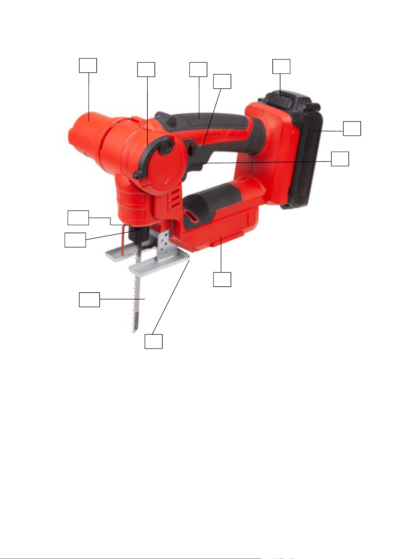
COMPONENT LIST
1. Motor cover
2. Pivot release lever
3. Hand grip areas
4. Lock-off button
5. Battery release button
6. Battery pack
1
11
8
7
6
5
4
12
3
2
10
9
8. Base plate
9. Foot plate
10. Blade
11. Blade holder
12. Protection finger
13. LED work light (See Fig. G)

7. On/off switch
Technical Specifications
Rated Voltage
18 V
No-load speed
2500/min
Stroke length
16 mm
Cutting capacity
Wood
50 mm
PVC pipe
45 mm
Steel
4 mm
Battery capacity
2000mAh
Charger input
220-240V~50/60Hz,70W
Charger output
20V 2.2 A
Charging time
1 h
Machine weight
1.4 kg / 3.09 lbs
Accessories
Wood cutting blade
1
Charger (JLH-H220-20U)
1
Metal cutting blade
1
battery pack(TK2020)
1
Aluminium cutting blade
1
Noise Information
A weighted sound pressure LpA =78 dB(A)
KpA= 3dB(A)
A weighted sound power LwA =89dB(A)
KwA= 3dB(A)
Wear ear protection.
Vibration Information
Vibration total values (triax vector sum) determined according to EN 62841:
cutting boards
Vibration emission value a
h,B
= 10.13 m/s
2
Uncertainty K = 1.5 m/s²
cutting steel metal
Vibration emission value a
h,M
= 6.96 m/s
2
Uncertainty K = 1.5 m/s²
Cutting wooden beams
Vibration emission value a
h,WB
= 4.17 m/s
2
Uncertainty K = 1.5 m/s²
The declared vibration total value and the declared noise emission value have been measured in accordance with a
standard test method and may be used for comparing one tool with another.
The declared vibration total value and the declared noise emission value may also be used in a preliminary assessment
of exposure.
WARNING: The vibration and noise emissions during actual use of the power tool can differ from the declared value
depending on the ways in which the tool is used especially what kind of workpiece is processed dependant on the
following examples and other variations on how the tool is used:
How the tool is used and the materials being cut or drilled.
The tool being in good condition and well maintained.
The use of the correct accessory for the tool and ensuring it is sharp and in good condition.
The tightness of the grip on the handles and if any anti vibration and noise accessories are used.
And the tool is being used as intended by its design and these instructions.
This tool may cause hand-arm vibration syndrome if its use is not adequately managed.
WARNING: To be accurate, an estimation of exposure level in the actual conditions of use should also take account of all
parts of the operating cycle such as the times when the tool is switched off and when it is running idle but not actually
doing the job. This may significantly reduce the exposure level over the total working period.
Helping to minimise your vibration and noise exposure risk.
Always use sharp chisels, drills and blades.
Maintain this tool in accordance with these instructions and keep well lubricated (where appropriate).
If the tool is to be used regularly then invest in anti vibration and noise accessories.
Plan your work schedule to spread any high vibration tool use across a number of days.
Assembly
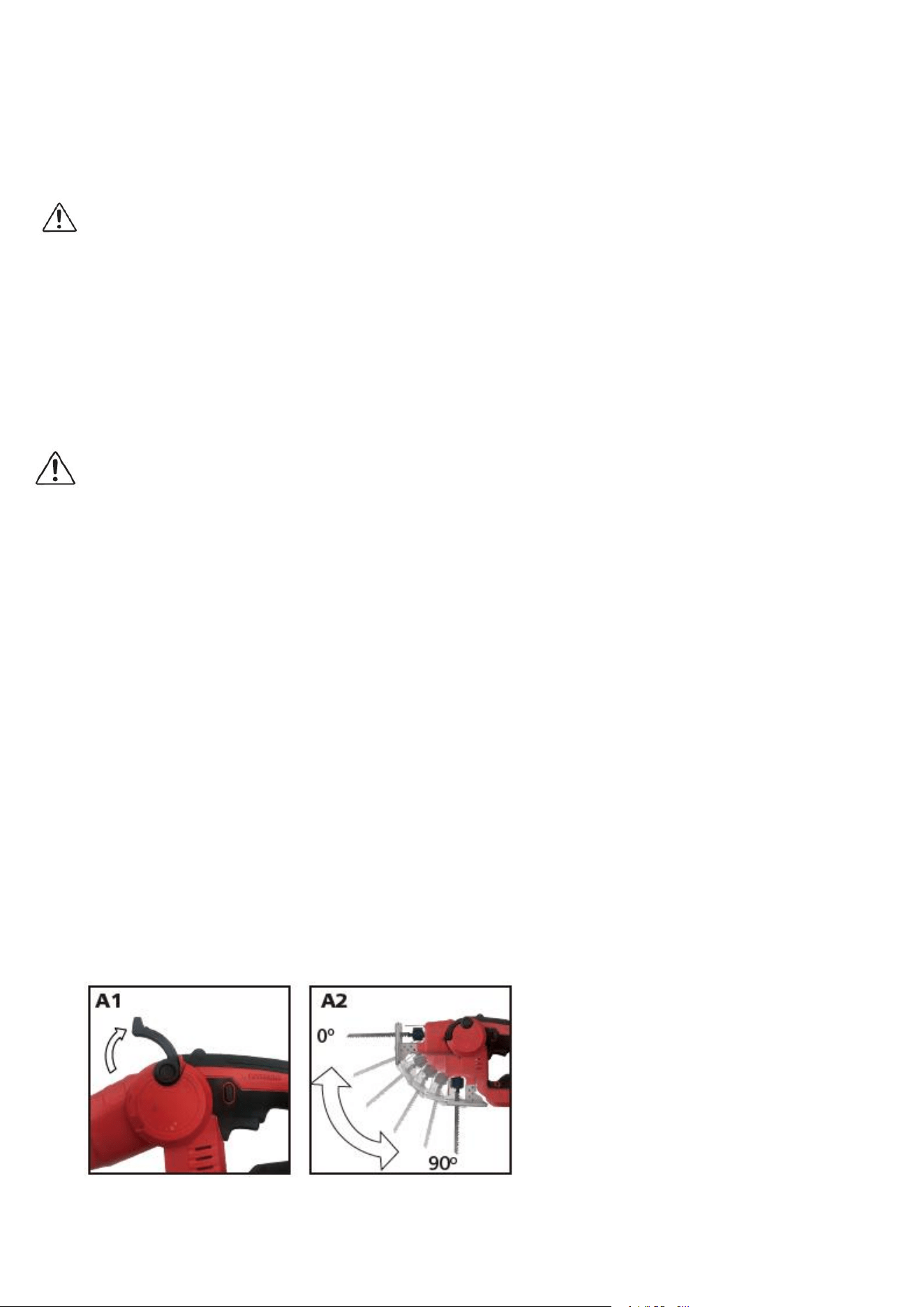
1. Working mode adjustment
This multi-purposed saw functions as a combination jigsaw and reciprocating saw. You can use the pivot release lever to
change the configuration.
1) Lift up the pivot release lever fully until it cannot be lifted further. (See Fig. A1)
2) Rotate the front portion of the saw into any of the 6 positions (0°, 18°, 36°, 54°, 72° and 90°) (See Fig. A2). Restore
the pivot release lever. Be sure to lock the pivot release lever in place.
In Position I (0°), this multi-purposed saw can be used as a reciprocating saw.
In Position VI (90°), this multi-purposed saw can be used as a jigsaw.
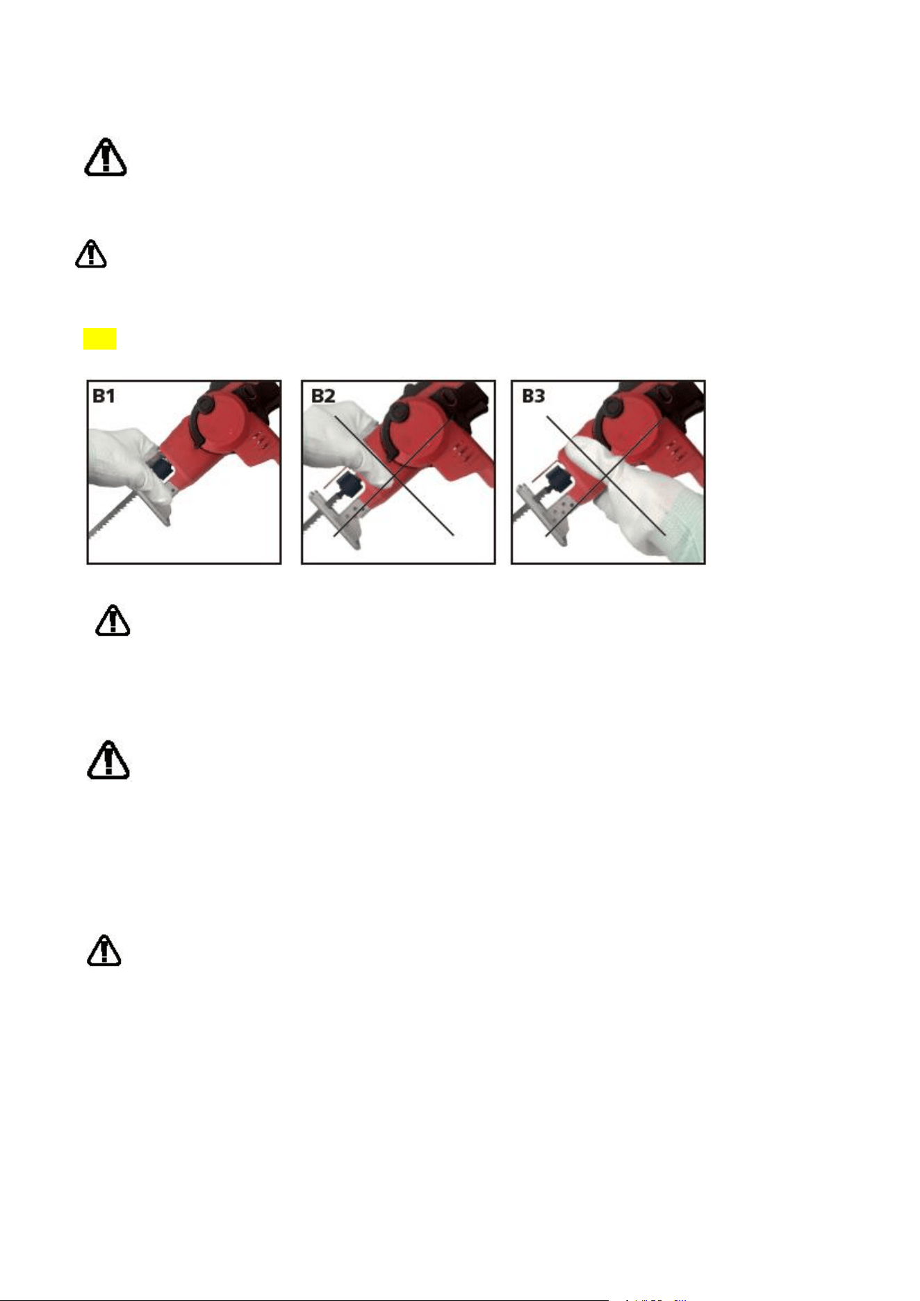
WARNING!
When adjusting the multi-purposed saw, you can only hold the foot plate as shown in Fig.B1. Never hold the
pivot head as shown in Fig. B2, B3.
WARNING!
To avoid being pinched, keep hands away from the hinge when changing positions.
To avoid the multi-purposed saw being turned on accidentally, remove the battery pack from the saw.
Before operation, make sure the pivot release lever is locked into position.
2. Inserting / removing the saw blade
WARNING! Before any work on the saw itself, remove the battery pack.
The blade should extend past both the foot plate and the thickness of the workpiece during the cut. Select the blade
best suitable for the material to be cut and use the shortest blade suitable for the thickness of the material.
WARNING! Cut hazard. Blade breakage may occur if the blade does not extend past the foot plate and the
workpiece during the cut. Increased risk of personal injury, as well as damage to the foot plate and
workpiece may result.
CAUTION: Remove the battery pack first to prevent switch actuation before making any adjustments or removing or
installing attachments or accessories.
Jig saw mode
——Inserting the saw blade
WARNING! Wear protective gloves when assembling the saw blade. Contact with the saw blade can lead to
injuries. You can only use the t-shank blade type as shown in Fig C1.
This multi-purposed saw is equipped with a tool-free blade holder. This makes possible easy and quick changing of the
saw blade without any additional tools.
1) Place the jig saw upside down, rotate the blade holder counter-clockwise and hold in position.
2) Fully insert the blade into the blade holder slot with blade teeth facing forward to the front of the saw.
3) Release the blade holder and it will self-rotate back to clamp the blade tightly. Push the blade to ensure it is locked
in position. (See Fig. C2)
NOTE: When using JIGSAW MODE, the blade teeth face forward to the front of the saw as shown in Fig. C3.
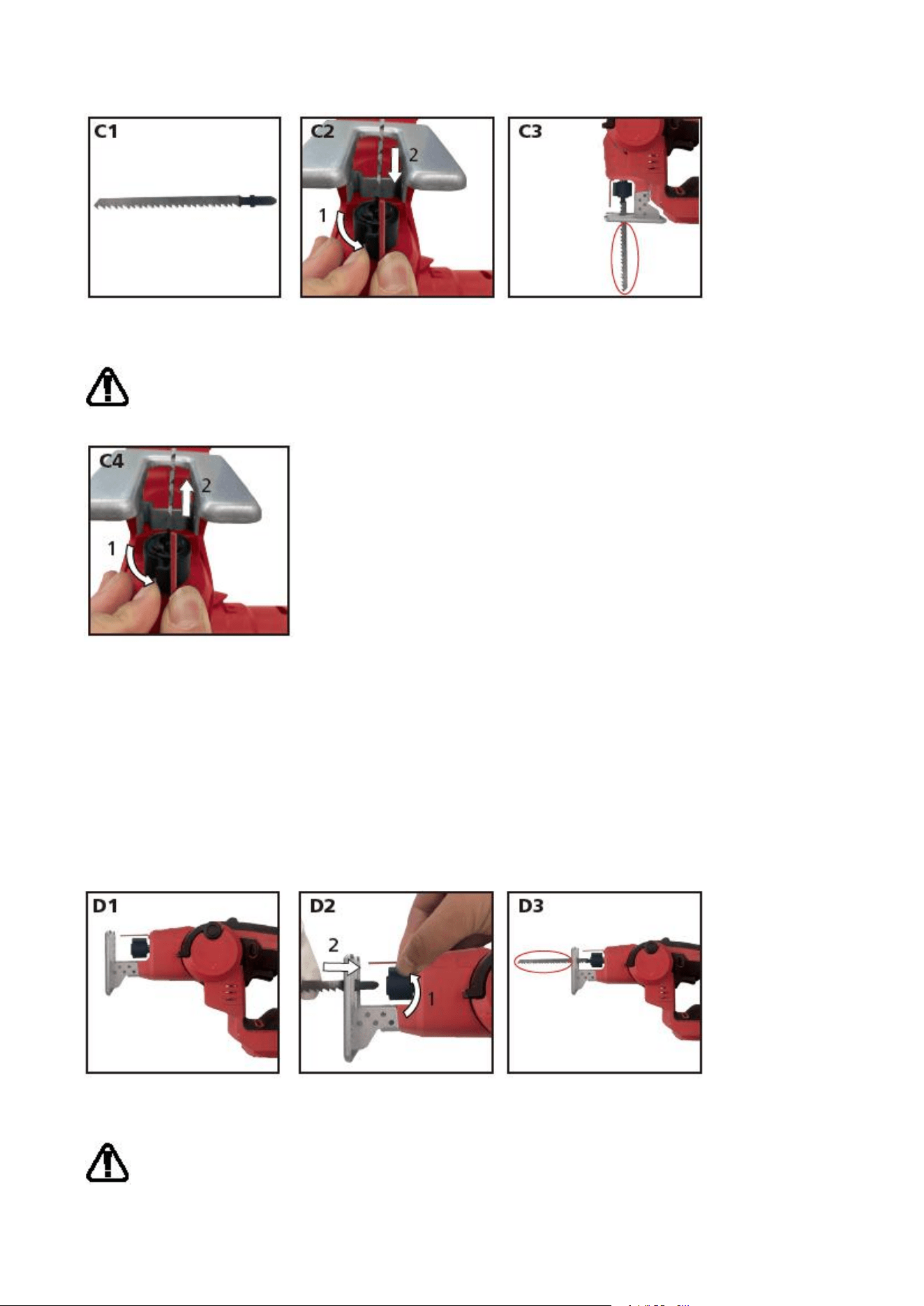
——Removing the saw blade
To remove a blade, place the jig saw upside down, hold the blade and rotate the blade holder counter-clockwise,
remove the blade from the blade holder slot and then release the blade holder. (See Fig. C4)
WARNING: The blade may be spring ejected so protect your eyes.
Reciprocating saw mode
——Inserting the saw blade
1) Lift up the pivot release lever fully and rotate the front portion of the saw into 0°positions to make this
multi-purpose saw to be a reciprocating saw. Restore the pivot release lever to lock (See Fig. D1).
2) Rotate the blade holder counter-clockwise and hold in position. Fully insert the blade into the blade holder slot
with blade teeth facing downwards to the base plate of the saw.
3) Release the blade holder, and it will self-rotate back to clamp the blade tightly. Push the blade to ensure it is locked
in position. (See Fig. D2)
NOTE: When using RECIPROCATING SAW MODE, the blade teeth face downwards to the base plate of the saw as shown
in Fig. D3.
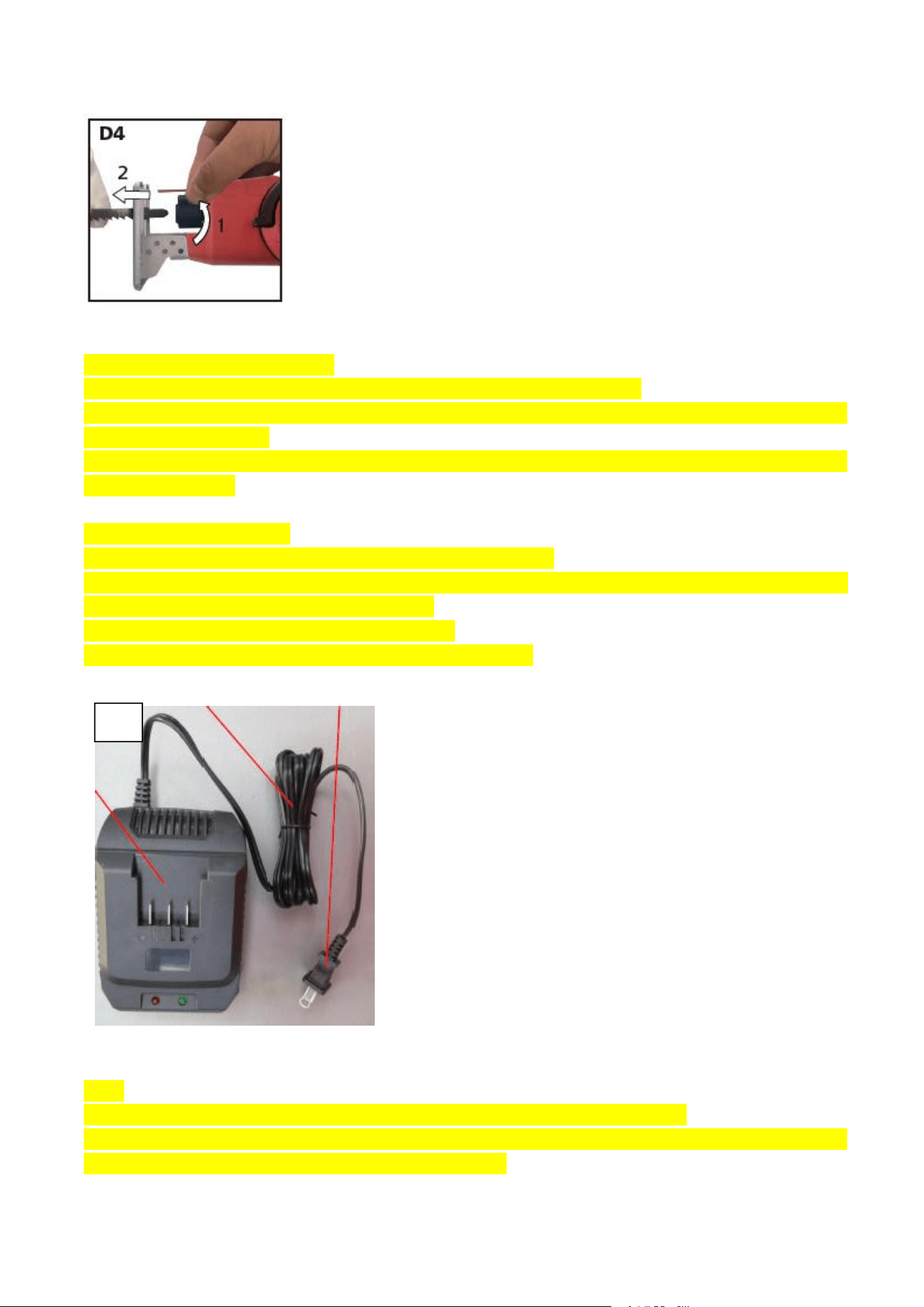
——Removing the saw blade
To remove a blade, hold the blade and rotate the blade holder counter-clockwise, remove the blade from the blade
holder slot and then release the blade holder . (See Fig. D4)
WARNING: The blade may be spring ejected so protect your eyes.
BEFORE PUTTING INTO OPERATION
1. CHARGING YOUR BATTERY PACK
Do not use any charger other than that specifically provided for use with the equipment.
If the battery pack is very hot you must remove your battery pack from the charger and allow time for the battery to
cool down before recharging.
Please charge the battery to reach full before storage. If the tool will not be used for long periods of time, charge the
battery every 3 months.
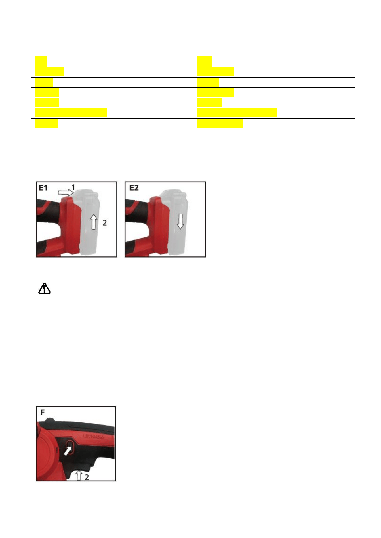
Charging procedure (See Fig. E1)
1) Plug the charger into an appropriate outlet. The light will be green flash.
2) Slide the battery pack into the charger, make sure the battery is in the correct charge position firmly. the light will
turn to red to indicate the charging process has started.
3) When charging is completed, the light will turn to green.
4) After fully charged, unplug the charger and remove the battery pack.
NOTE:
If the battery pack is locked in the charger, press the battery pack release button and remove it.
WARNING: When battery charge runs out after continuously use or exposure to direct sunlight or heat, allow time for
the tool to cool down before re-charging to achieve the full charge.
E1
Light
Status
Green flash
Standby mode
Red on
charging
Green on
Fully charged
Green on
Hot Delay
Red/green flash alternately
Defective Battery/Poor contact
Red flash
Pre-charged state
2. To remove or install the battery pack (See Fig. E1, E2)
Depress the battery pack release button firmly first and then slide the battery pack out from your multi-purposed saw.
Slide the fully charged battery pack onto the saw with sufficient force until it clicks into position.
Operation
WARNING:
Always wear eye protection while operating the saw.
BURN HAZARD. Do not touch the blade immediately after use. Contact with the blade may result in personal
injury.
Before you begin work, ensure the material to be cut is rigid. Small workpieces should be securely clamped to a
work table.
1. Switching on and off (See Fig. F)
For starting operation, press the lock-off button and hold in position, then press and hold the on/off switch. To switch
off the machine, release the on/off switch.
For safety reasons the on/off switch of the machine cannot be locked; it must remain pressed during the entire
operation.
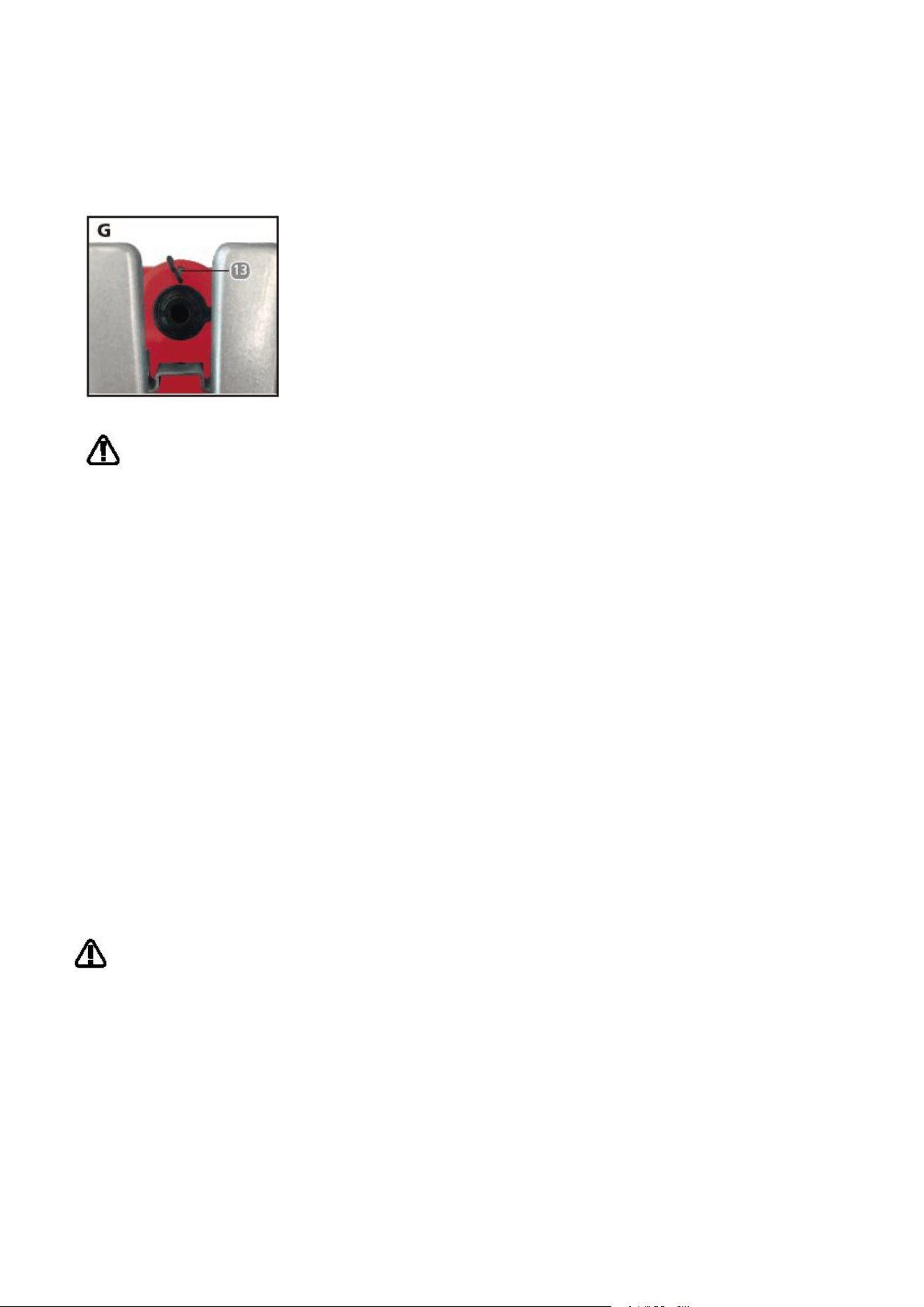
2. LED work light (See Fig. G)
A work light is built-in near the end of the protection finger. The light will automatically come on each time the on/off
switch is depressed.
3. Cutting
WARNING:
Always wear eye protection while operating the saw.
Never hold the pivot head when operating the tool.
Before cutting any type of material, be sure it is firmly anchored or clamped to prevent slipping. Holding the
work by hand or against your body leaves it unstable and may lead to loss of control.
Place blade lightly against work to be cut, depress the on/off switch and allow it to obtain maximum speed
before applying pressure.
Whenever possible, the saw foot plate must be held firmly against the material being cut. This will prevent the
saw from jumping or vibrating and minimize blade breakage.
Any cut which puts pressure on the blade, such as angle or scroll cuts, increases potential for vibration, kickback
and blade breakage.
Shock hazard. Use extra caution when cutting overhead and pay particular attention to overhead wires which
may be hidden from view.
Use extra caution when cutting overhead and anticipate the path of falling branches and debris ahead of time.
Inspect work site for hidden gas pipes, water pipes, or electrical wires before making blind or plunge cuts.
Failure to do so may result in explosion, property damage, electric shock, and/or serious personal injury.
Maintenance
WARNING: Remove the battery pack from the saw before carrying out any adjustment,
servicing or maintenance.
Your power tool requires no additional lubrication or maintenance.
There are no user serviceable parts in your power tool.
Never use water or chemical cleaners to clean your power tool.
Wipe clean with a dry cloth.
Always store your power tool in a dry place.
Keep the motor ventilation slots clean.
Keep all working controls free of dust.
Occasionally you may see sparks through the ventilation slots. This is normal and will not damage your power tool.
For battery tools
The ambient temperature range for tool and battery use and storage is 0℃-45℃.
The recommended ambient temperature range for the charging system during charging is 0℃-40℃.
FAQ/Troubleshooting
Working hints for your multi-purpose saw
General
1) Always use a blade suited to the material and material thickness to be cut.
2) Always ensure the work–piece is firmly held or clamped to prevent movement.
3) Any movement of the material may affect the quality of the cut. The blade cuts on the upward stroke and may chip
the uppermost surface.
Troubleshooting
Symptom
Possible Causes
Solution
The multi-purposed saw
suddenly stops during
operation.
Overload and battery temperature too
high
Relieve the load on the machine
immediately and allow cooling for
approx. 30 seconds by running the
machine on no-load.
Low battery capacity
Charge the battery pack.
Significantly reduced
cutting efficiency.
Worn blade
Replace a new blade.
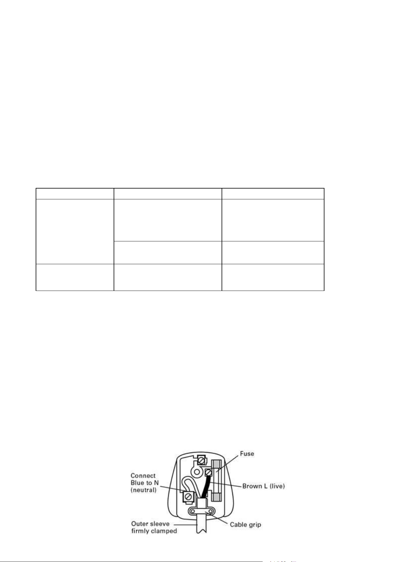
PLUG REPLACEMENT ( ONLY FOR REWIRABLE PLUG OF UK &
IRELAND)
If you need to replace the fitted plug then follow the instructions below.
IMPORTANT
The wires in the mains lead are colored in accordance with the following code:
BLUE =NEUTRAL
Brown = Live
As the colors of the wires in the mains lead of this appliance may not correspond with the colored markings identifying the
terminals in your plug, proceed as follows. The wire which is colored blue must be connected to the terminal which is
marked with N. The wire which is colored brown must be connected to the terminal which is marked with L.
Warning!
Never connect live or neutral wires to the earth terminal of the plug. Only fit an approved BS1363/A plug and the correct
rated current fuse which is used in the plug.
Note: If a moulded plug is fitted and has to be removed take great care in disposing of the plug and severed cable, it must
be destroyed to prevent engaging into a socket.

DECLARATION OF CONFORMITY
Declare that the product
Description Battery operated reciprocating Saw
Type Designation TLJS02D (designation of machinery, representative of battery operated reciprocating Saw)
Function Sawing various materials