

Visit our website at: http://www.harborfreight.com
Email our technical support at: [email protected]
23703E-B
22"
VARIABLE-SPEED
SCROLL SAW
59416
Owner’s Manual & Safety Instructions
Save This Manual Keep this manual for the safety warnings and precautions, assembly,
operating, inspection, maintenance and cleaning procedures. Write the product’s serial number in the
back of the manual near the assembly diagram (or month and year of purchase if product has no number).
Keep this manual and the receipt in a safe and dry place for future reference. 24b
When unpacking, make sure that the product is intact
and undamaged. If any parts are missing or broken,
please call 1-888-866-5797 as soon as possible.
Copyright
©
2023 by Harbor Freight Tools
®
. All rights reserved.
No portion of this manual or any artwork contained herein may be reproduced in
any shape or form without the express written consent of Harbor Freight Tools.
Diagrams within this manual may not be drawn proportionally. Due to continuing
improvements, actual product may differ slightly from the product described herein.
Tools required for assembly and service may not be included.
Read this material before using this product.
Failure to do so can result in serious injury.
SAVE THIS MANUAL.
Page 2 For technical questions, please call 1-888-866-5797. 59416
SaFety OperatiOn MaintenanceSetup
table of contents
Safety ......................................................... 2
Specifications ............................................. 6
Setup .......................................................... 6
Operation .................................................... 8
Maintenance .............................................. 10
Parts List and Diagram .............................. 14
Warranty .................................................... 16
WarninG SyMBOLS anD DeFinitiOnS
This is the safety alert symbol. It is used to alert you to potential
personal injury hazards. Obey all safety messages that
follow this symbol to avoid possible injury or death.
Indicates a hazardous situation which, if not avoided,
will result in death or serious injury.
Indicates a hazardous situation which, if not avoided,
could result in death or serious injury.
Indicates a hazardous situation which, if not avoided,
could result in minor or moderate injury.
Addresses practices not related to personal injury.
iMpOrtant SaFety inFOrMatiOn
General tool Safety Warnings
read all safety warnings and instructions.
Failure to follow the warnings and instructions may result in electric shock, fire and/or serious injury.
Save all warnings and instructions for future reference.
1. KEEP GUARDS IN PLACE and in working order.
2. REMOVE ADJUSTING KEYS AND
WRENCHES. Form habit of checking to
see that keys and adjusting wrenches are
removed from tool before turning it on.
3. KEEP WORK AREA CLEAN.
Cluttered areas and benches invite accidents.
4. DON’T USE IN DANGEROUS ENVIRONMENT.
Don’t use power tools in damp or wet locations,
or expose them to rain. Keep work area well lighted.
5. KEEP CHILDREN AWAY. All visitors should
be kept safe distance from work area.
6. MAKE WORKSHOP KID PROOF with padlocks,
master switches, or by removing starter keys.
7. DON’T FORCE TOOL. It will do the job better
and safer at the rate for which it was designed.
8. USE RIGHT TOOL. Don’t force tool or attachment
to do a job for which it was not designed.

Page 3For technical questions, please call 1-888-866-5797. 59416
SaFetyOperatiOnMaintenance Setup
table a: recOMMenDeD MiniMuM Wire GauGe
FOr eXtenSiOn cOrDS
(120 VOLt)
naMepLate
aMpereS
(at full load)
eXtenSiOn cOrD
LenGtH
25′ 50′ 100′ 150′
0 – 6 18 16 16 14
6.1 – 10 18 16 14 12
10.1 – 12 16 16 14 12
12.1 – 16 14 12 Do not use.
table a
9. USE PROPER EXTENSION CORD. Make sure
your extension cord is in good condition. When
using an extension cord, be sure to use one heavy
enough to carry the current your product will draw.
An undersized cord will cause a drop in line voltage
resulting in loss of power and overheating.
Table A shows the correct size to use depending
on cord length and nameplate ampere rating.
If in doubt, use the next heavier gauge.
The smaller the gauge number, the heavier the cord.
10. WEAR PROPER APPAREL. Do not wear
loose clothing, gloves, neckties, rings, bracelets,
or other jewelry which may get caught in moving
parts. Nonslip footwear is recommended.
Wear protective hair covering to contain long hair.
11. ALWAYS USE SAFETY GLASSES. Also
use face or dust mask if cutting operation is
dusty. Everyday eyeglasses only have impact
resistant lenses, they are NOT safety glasses.
12. SECURE WORK. Use clamps or a vise to
hold work when practical. It’s safer than using
your hand and it frees both hands to operate tool.
13. DON’T OVERREACH.
Keep proper footing and balance at all times.
14. MAINTAIN TOOLS WITH CARE. Keep
tools sharp and clean for best and safest
performance. Follow instructions for
lubricating and changing accessories.
15. DISCONNECT TOOLS before servicing;
when changing accessories, such as
blades, bits, cutters, and the like.
16. REDUCE THE RISK OF UNINTENTIONAL
STARTING. Make sure switch is in
off position before plugging in.
17. USE RECOMMENDED ACCESSORIES.
Consult the owner’s manual for recommended
accessories. The use of improper accessories
may cause risk of injury to persons.
18. NEVER STAND ON TOOL.
Serious injury could occur if the tool is tipped or
if the cutting tool is unintentionally contacted.
19. CHECK DAMAGED PARTS. Before further use
of the tool, a guard or other part that is damaged
should be carefully checked to determine that
it will operate properly and perform its intended
function – check for alignment of moving parts,
binding of moving parts, breakage of parts,
mounting, and any other conditions that may
affect its operation. A guard or other part that is
damaged should be properly repaired or replaced.
20. DIRECTION OF FEED.
Feed work into a blade or cutter against the
direction of rotation of the blade or cutter only.
21. NEVER LEAVE TOOL RUNNING UNATTENDED.
TURN POWER OFF. Don’t leave tool
until it comes to a complete stop.
Page 4 For technical questions, please call 1-888-866-5797. 59416
SaFety OperatiOn MaintenanceSetup
Grounding instructions
tO preVent eLectric SHOcK anD DeatH FrOM incOrrect
GrOunDinG Wire cOnnectiOn reaD anD FOLLOW tHeSe inStructiOnS:
110-120 Vac Grounded tools: tools with three prong plugs
1. In the event of a malfunction or breakdown,
grounding provides a path of least resistance for
electric current to reduce the risk of electric shock.
This tool is equipped with an electric cord having an
equipment-grounding conductor and a grounding
plug. The plug must be plugged into a matching
outlet that is properly installed and grounded in
accordance with all local codes and ordinances.
2. Do not modify the plug provided – if it will
not fit the outlet, have the proper outlet
installed by a qualified electrician.
3. Improper connection of the equipment-grounding
conductor can result in a risk of electric shock.
The conductor with insulation having an outer
surface that is green with or without yellow
stripes is the equipment-grounding conductor.
If repair or replacement of the electric cord or
plug is necessary, do not connect the equipment-
grounding conductor to a live terminal.
4. Check with a qualified electrician or service
personnel if the grounding instructions are
not completely understood, or if in doubt as
to whether the tool is properly grounded.
5. Use only 3-wire extension cords that
have 3-prong grounding plugs and 3-pole
receptacles that accept the tool’s plug.
6. Repair or replace damaged or
worn cord immediately.
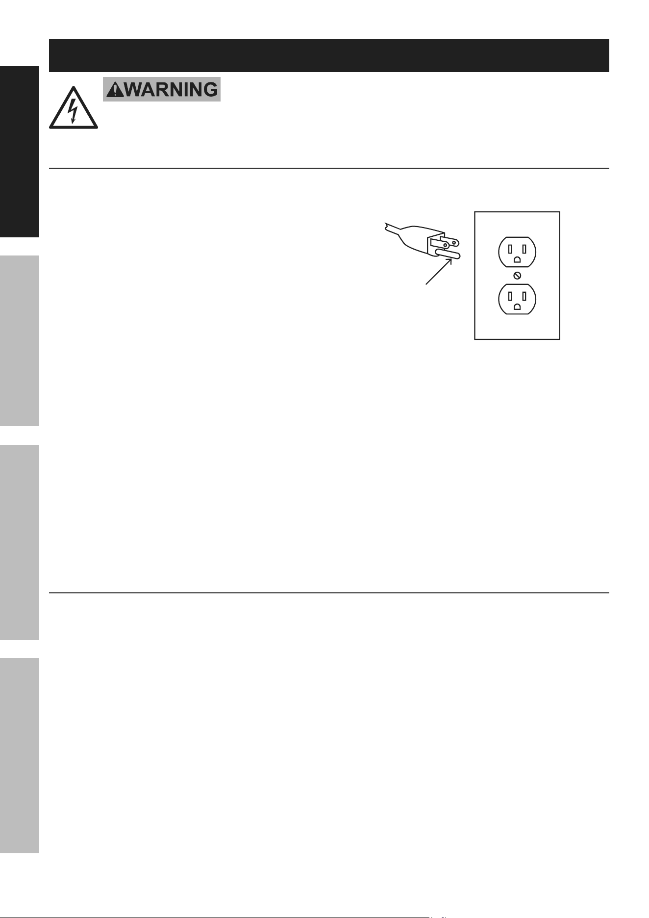
Grounding
pin
125 Vac 3-prong plug and Outlet
(for up to 125 Vac and up to 15 a)
7. This tool is intended for use on a circuit that has
an outlet that looks like the one illustrated above in
125 Vac 3-prong plug and Outlet. The tool has
a grounding plug that looks like the plug illustrated
above in 125 Vac 3-prong plug and Outlet.
8. The outlet must be properly installed and grounded
in accordance with all codes and ordinances.
9. Do not use an adapter to connect
this tool to a different outlet.
Scroll Saw Safety Warnings
For your Own Safety read instruction
Manual Before Operating Scroll Saw
1. Wear eye protection.
2. DO nOt Operate WitH any GuarD
DiSaBLeD, DaMaGeD, Or reMOVeD. Moving
guards must move freely and close instantly.
3. The use of accessories or attachments not
recommended by the manufacturer may
result in a risk of injury to persons.
4. When servicing use only identical replacement parts.
5. Only use safety equipment that has been approved
by an appropriate standards agency. Unapproved
safety equipment may not provide adequate
protection. Eye protection must be ANSI-approved
and breathing protection must be NIOSH-approved
for the specific hazards in the work area.
6. Stay alert, watch what you are doing and use
common sense when operating a power tool.
Do not use a power tool while you are tired or
under the influence of drugs, alcohol or medication.
A moment of inattention while operating power
tools may result in serious personal injury.
7. Industrial applications must follow OSHA guidelines.
8. Maintain labels and nameplates on the tool.
These carry important safety information.
If unreadable or missing, contact
Harbor Freight Tools for a replacement.
9. Avoid unintentional starting.
Prepare to begin work before turning on the tool.

Page 5For technical questions, please call 1-888-866-5797. 59416
SaFetyOperatiOnMaintenance Setup
10. People with pacemakers should consult their
physician(s) before use. Electromagnetic fields in
close proximity to heart pacemaker could cause
pacemaker interference or pacemaker failure.
11. The warnings, precautions, and instructions
discussed in this instruction manual cannot cover all
possible conditions and situations that may occur.
It must be understood by the operator that
common sense and caution are factors
which cannot be built into this product,
but must be supplied by the operator.
Vibration Safety
This tool vibrates during use. Repeated or
long-term exposure to vibration may cause
temporary or permanent physical injury,
particularly to the hands, arms and shoulders.
To reduce the risk of vibration-related injury:
1. Anyone using vibrating tools regularly or for an
extended period should first be examined by a
doctor and then have regular medical check-ups
to ensure medical problems are not being caused
or worsened from use. Pregnant women or
people who have impaired blood circulation to
the hand, past hand injuries, nervous system
disorders, diabetes, or Raynaud’s Disease should
not use this tool. If you feel any medical or
physical symptoms related to vibration (such as
tingling, numbness, and white or blue fingers),
seek medical advice as soon as possible.
2. Do not smoke during use. Nicotine reduces
the blood supply to the hands and fingers,
increasing the risk of vibration-related injury.
3. Use tools with the lowest vibration when there
is a choice between different processes.
4. Include vibration-free periods each day of work.
5. Grip workpiece as lightly as possible (while still
keeping safe control of it). Let the tool do the work.
6. To reduce vibration, maintain the tool as
explained in this manual. If any abnormal
vibration occurs, stop use immediately.
SaVe tHeSe inStructiOnS.

Page 6 For technical questions, please call 1-888-866-5797. 59416
SaFety OperatiOn MaintenanceSetup
Specifications
Electrical Rating 120VAC / 60Hz / 1.3A S1, 1.6A S2 30min
Arm Tilt 45° Right and 30° Left
Max Cutting Thickness 2"
Blade Type 5" L Pinless Blade
Throat Depth 22"
Blade Stroke 3/4"
Cutting Speed 360 to 1600/min
Base Mounting Holes 4x Ø10mm (3/8") holes
Accessories
4x Adjustable Foot, Ø30 x 11mm with M8 Bolts and Nuts
1x Hex Key S4 x 65mm
1x Hex Key S3 x 58mm
1x Spare 5" L Pinless Blade
Setup - Before use:
read the entire iMpOrtant SaFety inFOrMatiOn section at the beginning of this
manual including all text under subheadings therein before set up or use of this product.
tO preVent SeriOuS inJury FrOM acciDentaL OperatiOn:
turn the power Switch of the tool off and unplug the tool from its electrical outlet
before performing any procedure in this section.
note: For additional information regarding the parts listed in the following pages,
refer to the Assembly Diagram near the end of this manual.
assembly/Mounting
attaching to Bench top
1. Pick a solid wood workbench to attach the Saw.
The workbench must be stable, and able to support
the weight of the Saw and the material being cut.
2. Find the four 3/8" mounting holes in corners of
the Saw′s Base and mark through the holes for
drilling with a 3/8 inch drill bit (drill and bit sold
separately). Remove Saw and drill pilot holes.
3. Replace Saw over holes and attach with the
following hardware (sold separately): Four sets
of 1/4″ bolts, washers, lock washers, and nuts.
4. Check that all mounting screws and nuts
are tight before using the Saw.
placing on Bench top
1. Pick a solid wood workbench to mount the Saw.
The workbench must be stable, and able to support
the weight of the Saw and the material being cut.
2. Find the four 3/8″ mounting holes, one in
each corner of the Saw′s Base. Attach one
Ø30 x 11mm Adjustable Foot (accessory)
to each hole using the supplied M8 Bolt
and Nut. Tighten to secure.
caution: Do not carry Saw by upper arm
or Motor. Carry Saw by Base or Table.
3. Check that the feet are secure then place the
Saw on a level Bench top. Check that the Saw
is stable and flat on the bench before using it.
Base
adjustable
Foot, Ø30
x 11mm
Bolt, M8
nut, M8
Mounting Hole
(one at each corner)
Page 7For technical questions, please call 1-888-866-5797. 59416
SaFetyOperatiOnMaintenance Setup
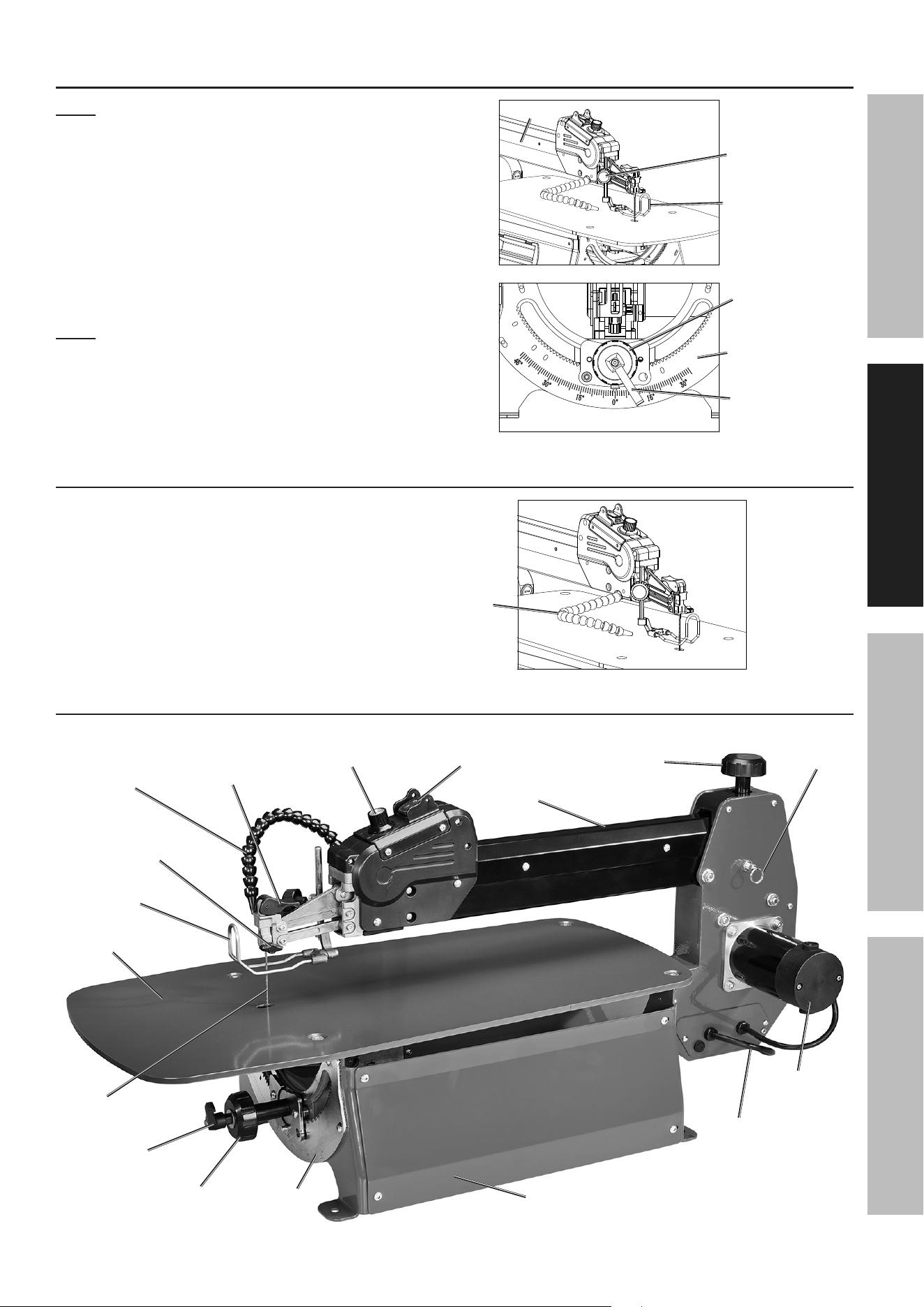
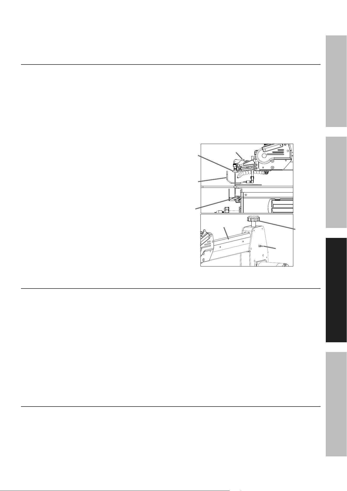
align Bevel Scale indicator
note: The Bevel Scale Indicator has been adjusted at
the factory but should be checked before using the Saw.
1. Loosen the Guard Height Adjustment knob
and move the Blade Guard all the way up.
2. Verify the Indicator is pointing to “0” degrees on the
Scale. If its not, loosen the Bevel Lock Handle and
turn the Bevel Knob until the Arm is at the right angle
to the Blade and the Indicator is pointing to ″0″.
3. Retighten Bevel Lock Handle.
note: The Bevel Scale Indicator is only a guide and
should not be relied upon for precision settings.
Make practice cuts in scrap wood to determine if
the angle settings are correct.
Blade Guard
Guard Height
adjustment
Bevel Lock
Handle
Bevel Knob
Scale
arm
adjust Dust Blower tube
Adjust the Air Blower Tube so the air is
directed at both the blade and workpiece.
air
Blower
tube
Functions
top Blade
Lock Knob
pull
ring pin
power
Switch
Speed
control Knob
table
Blade
arm Height
Knob
Blade Guard
Bevel Lock
Handle
Blade tension
Handle
air
Blower
tube
Bevel Knob
Motor
power
cord
Base
upper arm
Scale
Page 8 For technical questions, please call 1-888-866-5797. 59416
SaFety OperatiOn MaintenanceSetup
Operating instructions
read the entire iMpOrtant SaFety inFOrMatiOn section at the beginning of this
manual including all text under subheadings therein before set up or use of this product.
tO preVent SeriOuS inJury FrOM acciDentaL OperatiOn:
turn the power Switch of the tool off and unplug the tool from its electrical outlet
before performing any procedure in this section.
tO preVent SeriOuS inJury:
DO nOt Operate WitH any GuarD DiSaBLeD, DaMaGeD, Or reMOVeD.
Moving guards must move freely and close instantly.
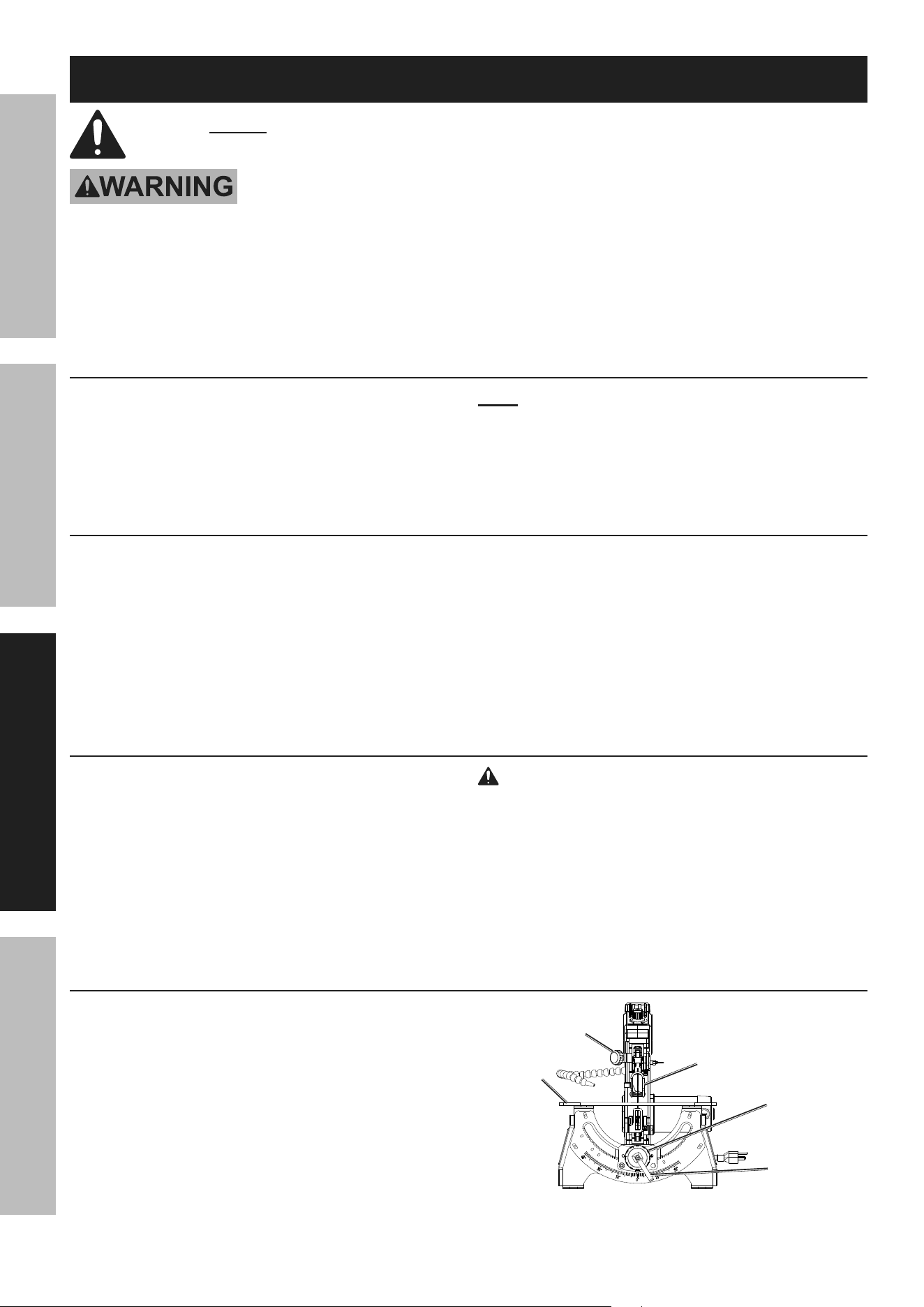
arm angle adjustment
The Saw Arm can be adjusted between
45° Right and 30° Left as follows:
1. Loosen the Bevel Lock Handle and move the
Arm using the Bevel Knob until the desired
angle is reached as indicated on the Scale.
note: The Arm has positive stops at:
Right 0, 22.5, 30, 45°
Left 30°.
2. Tighten the Bevel Lock Handle.
Workpiece and Work area Set up
1. Designate a work area that is clean and well-lit.
The work area must not allow access by children
or pets to prevent distraction and injury.
2. Route the Power Cord along a safe route to reach
the work area without creating a tripping hazard or
exposing the Cord to possible damage. The Power
Cord must reach the work area with enough extra
length to allow free movement while working.
3. There must not be objects, such as utility lines,
nearby that will present a hazard while working.
turning On and adjusting Speed
1. Plug Power Cord into a 120VAC
grounded AC receptacle.
2. To turn Saw ON, set the Power Switch (I/O) to ″I″.
3. Set speed (strokes per minute) by turning the
Speed Control Knob. When first starting the Saw,
set the knob to the middle then turn toward ″H″ to
increase speed and toward ″L″ to lower the speed.
4. To turn Saw OFF, set the Power Switch to ″O″.
WarninG! tO preVent SeriOuS
inJury: Keep hands and fingers away
from the moving Saw Blade.
5. To prevent accidents, turn Power Switch OFF, and
unplug the Saw from its electrical outlet after use.
Clean, then store the Saw indoors
out of children’s reach.
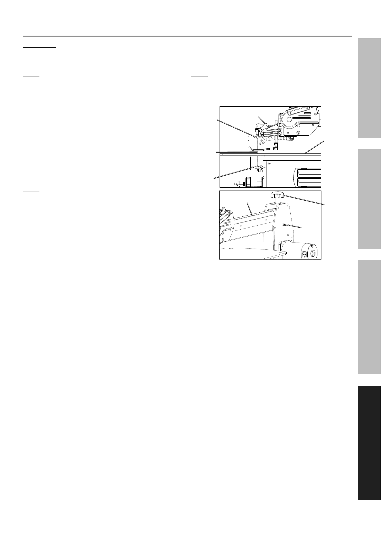
Straight, cross, Bevel cuts, and ripping
1. Using a pencil, mark the design cut-line
on the workpiece.
2. Slide the workpiece underneath the Blade Guard
foot. If necessary, adjust the foot by loosening the
Guard Height Adjustment knob and sliding the foot
up or down until it lightly rests on the workpiece.
Tighten the Guard Height Adjustment knob. Do not
allow the workpiece to contact the Blade yet.
3. Turn the Power Switch ON and
the Blade will start moving.
Blade
Guard
Guard Height
adjustment
Bevel
Knob
Bevel Lock
Handle
table
Page 9For technical questions, please call 1-888-866-5797. 59416
SaFetyOperatiOnMaintenance Setup
4. Using both hands, carefully guide the workpiece into
the Blade. Press down on the workpiece and slowly
guide it through the Saw Blade. Do not force the
material through the Blade or the Blade could break.
5. When cutting is complete, move workpiece beyond
the Blade Guard foot and turn Power Switch OFF.
Unplug the Saw from its electrical outlet after use.
inside cuts
1. Using a pencil, mark the cut-line on the workpiece.
2. Drill a pilot hole in the workpiece that is
a little larger than the blade width.
3. Loosen Blade from top clamp by flipping
the Tension Handle up and loosening
the Top Blade Locking Knob.
4. Gently lift the Upper Arm of the Saw, then
once at desired height, listen for a ″click″ that
signifies the Arm has locked in place.
5. Carefully guide blade through pilot hole while
lowering workpiece to table. Do not deflect blade.
6. While holding the Upper Arm, pull the
Ring Pin and guide the Arm down so that
the Blade is fee back into the top clamp.
Be sure Arm locks (″clicks″) in place.
7. Turn Arm Height Knob to adjust the Arm′s
vertical position. Then secure blade by
tightening Top Blade Locking Knob and
pushing the Blade Tension Handle down.
8. Adjust the Blade Guard foot by loosening the
Guard Height Adjustment knob and sliding the foot
up or down until it lightly rests on the workpiece.
9. Use one hand to hold workpiece and other
hand to turn the Power Switch ON.
10. Hold workpiece with both hands while guiding and
pressing down on it until the cut is complete.
11. When finished turn the Power Switch OFF and
unplug the Saw from the electrical outlet.
12. Flip the Blade Tension Handle up. Loosen the
Top and Lower Blade Locking Knobs.
Loosen the Blade Guard foot and remove the Blade.
13. Raise the Upper Arm away from the workpiece and
ensure it clicks in place. Remove the workpiece.
14. Reattach Saw Blade by following steps 2-5 in
Removing and Installing Blades on page 11.
Blade tension
Handle
top
Blade
Locking
Knob
upper arm
ring
pin
arm
Height
Knob
Blade
Guard
Lower
Blade
Locking
Knob
Blade
curved cuts
1. Mark the entire cutting line with a pencil. If a
template is available, use it as a marking guide.
2. Slide the workpiece underneath the Blade Guard
foot. If necessary, adjust the foot by loosening the
Guard Height Adjustment knob and sliding the foot
up or down until it lightly rests on the workpiece.
Tighten the Guard Height Adjustment knob. Do not
allow the workpiece to contact the Blade yet.
3. Turn the Power Switch ON.
4. Using both hands, carefully guide the workpiece
into the Saw Blade. Press down on the workpiece
and slowly guide it through the Blade. Do
not force the material through the Blade.
5. When cutting curves, be careful not
to twist the Blade out of line.
6. If the curve cut is forced off the cut-line,
back the material off the Saw Blade and
start a new, straight cut through a scrap
section of the material. Begin the curved cut
again from an appropriate angle point.
7. When cutting is complete, move workpiece beyond
the Blade Guard foot and turn Power Switch OFF.
Unplug the Saw from its electrical outlet after use.
Jamming of Saw Blade and Workpiece
1. If the Saw Blade jams in the workpiece,
immediately turn the Power Switch OFF and
unplug the Power Cord from its electrical outlet.
2. Wait until the Saw Blade has come to a complete
stop, then remove the Saw Blade as described in
Removing and Installing Blades on page 11. The
workpiece will come with it.
3. Place a flat bladed screwdriver in the cut and
force it open. Remove the Saw Blade.
4. Reinstall the Saw Blade on the machine and set
the proper tension as described in Removing
and Installing Blades on page 11.

Page 10 For technical questions, please call 1-888-866-5797. 59416
SaFety OperatiOn MaintenanceSetup
Maintenance and Servicing
procedures not specifically explained in this manual must
be performed only by a qualified technician.
tO preVent SeriOuS inJury FrOM acciDentaL OperatiOn:
turn the power Switch of the tool off and unplug the tool from its electrical outlet
before performing any procedure in this section.
tO preVent SeriOuS inJury FrOM tOOL FaiLure:
Do not use damaged equipment. if abnormal noise or vibration
occurs, have the problem corrected before further use.
cleaning and Maintenance
1. BeFOre eacH uSe, inspect the general
condition of the tool. Check for:
• loose hardware
• misalignment or binding of moving parts
• cracked or broken parts
• damaged electrical wiring
• any other condition that may
affect its safe operation.
2. aFter uSe, wipe external surfaces
of the tool with clean cloth.
3. Periodically recheck all nuts, bolts,
and screws for tightness.
4. Applying a light coat of paste wax on the Saw
Table allows the material being cut to glide
smoothly across the Table surface. Buff the
wax off with a clean cloth after application.
5. Periodically apply a light coat of dry lubricant
to the inside of the blade bevel rails.
The motor bearings, interior bearing, and
table bevel rail bearings are all sealed
and require no additional lubrication.
6. Wear ANSI-approved safety goggles and
NIOSH-approved breathing protection, and
clean the Saw by using compressed air
to blow off dirt and dust.
note: Use low-pressure compressed air,
not exceeding 25 PSI, around the blade
holders, blade bevel rails, and blade.
7. Store in a clean and dry location.
8. Over time, if the performance of the Saw diminishes,
or it stops working completely, it may be necessary
to replace the Carbon Brushes in the Motor by
removing the Carbon Brush Holder and inspecting
the Carbon Brushes. This procedure should
be completed by a qualified technician. If the
Carbon Brushes are not worn down, try cleaning
the Carbon Brush tips with an ink eraser.
WarninG! tO preVent SeriOuS
inJury: if the supply cord of this power
tool is damaged, it must be replaced only
by a qualified service technician.
Page 11For technical questions, please call 1-888-866-5797. 59416
SaFetyOperatiOnMaintenance Setup
removing and installing Blades
WarninG! tO preVent SeriOuS inJury FrOM acciDentaL OperatiOn:
turn the power Switch of the tool off and unplug the tool from
its electrical outlet before making any adjustments to the Blade.
note: Replacement blades sold separately.
1. Flip the Blade Tension Handle up.
Loosen the Top and Lower Blade Locking Knobs.
Remove the Blade.
2. Before installing the new Blade, verify
the Upper Arm is perfectly parallel to the
work table. This will ensure the Blade
cuts perpendicular to the work table.
3. Slide Blade into the blade clamp deep enough to
gain sufficient clamping surface, but not all the
way which can result in the Blade being too short
for sufficient gripping by the upper blade clamp.
note: The Saw Blade must be installed so
that its teeth are facing forward (front cutting)
and always pointing down.
4. Tighten the Lower Blade Locking
Knob to lock the Blade in place.
5. Insert the top of the Blade into the top clamp
and tighten the Top Blade Locking Knob.
6. Push the Blade Tension Handle down. If
needed, turn the Arm Height Knob
to fine tine the blade tension.
note: A properly tensioned Blade will make a
high-C sound (C6, 1047 Hz) when plucked with a
finger. Over or under tensioning of the blade may
cause premature breakage during operation.
Blade tension
Handle
top
Blade
Locking
Knob
upper arm
ring
pin
arm
Height
Knob
Blade
Lower
Blade
Locking
Knob
table
Blade Selection
Woodworking blade sizes range from #3/0 to #12. Choose the appropriate blade for the type wood to
be cut, thickness, and type of cut to be done. The blade should be five inches long and pinless.

Page 12 For technical questions, please call 1-888-866-5797. 59416
SaFety OperatiOn MaintenanceSetup
troubleshooting
problem possible causes Likely Solutions
Blades breaking 1. Wrong blade tension.
2. Over-working blade.
3. Wrong blade application.
4. Blade twisting in wood.
1. Adjust blade tension.
2. Reduce feed cut rate.
3. Use narrow blades for cutting thin wood,
wide blades for cutting thicker wood.
4. Avoid side pressure on blade.
Motor does
not run
1. No power at outlet.
2. Defective power cord or plug.
3. Defective motor.
4. Worn carbon brush.
1. Check power source.
2. Repair or replace defective parts.
3. Have motor repaired or replaced by
a qualified service technician.
4. Have carbon brush replaced by qualified technician.
Excessive
Vibration
1. Improper base mounting.
2. Unsuitable mounting surface.
3. Loose motor mounting.
1. Make sure mounting hardware is secure.
2. The heavier the work bench, the
less vibration will occur.
3. Check that motor mounting hardware is secure.
Blade not in line
with arm motion
Blade holders not aligned. Flip the Blade Tension Handle up, then loosen
the Top and Lower Blade Locking Knobs. Once
adjusted, push the Blade Tension Handle
back down. Then, turn the Arm Height Knob
to adjust the Arm′s vertical position.
Tool will
not start
1. Power cord not connected.
2. No power at outlet.
3. Tool’s thermal reset breaker
tripped (if equipped).
4. Internal damage or wear. (Carbon
brushes or switch, for example.)
1. Check that cord is plugged in.
2. Check power at outlet. If outlet is unpowered,
turn off tool and check circuit breaker.
If breaker is tripped, make sure circuit is right
capacity for tool and circuit has no other loads.
3. Turn off tool and allow to cool.
Press reset button on tool.
4. Have technician service tool.
Tool operates
slowly
Extension cord too long or
wire size too small.
Eliminate use of extension cord. If an extension cord
is needed, use one with the proper diameter for
its length and load. See table a on page 3.
Performance
decreases
over time
1. Saw blade dull or damaged.
2. Carbon brush worn or damaged.
1. Replace saw blade.
2. Have qualified technician replace brush.
Excessive noise
or rattling
Internal damage or wear. (Carbon
brushes or bearings, for example.)
Have technician service tool.
Overheating 1. Forcing machine to work too fast.
2. Saw blade dull or damaged.
3. Motor being strained by long or
small diameter extension cord.
1. Allow machine to work at its own rate.
2. Replace saw blade.
3. Eliminate use of extension cord.
If an extension cord is needed, use one with
the proper diameter for its length and load.
See table a on page 3.
Follow all safety precautions whenever diagnosing or servicing the tool.
Disconnect power cord before service.

Page 13For technical questions, please call 1-888-866-5797. 59416
SaFetyOperatiOnMaintenance Setup
record product’s Serial number Here:
note: If product has no serial number, record month and year of purchase instead.
note: Some parts are listed and shown for illustration purposes only, and are not available
individually as replacement parts. Specify UPC 193175469687 when ordering parts.
pLeaSe reaD tHe FOLLOWinG careFuLLy
THE MANUFACTURER AND/OR DISTRIBUTOR HAS PROVIDED THE PARTS LIST AND ASSEMBLY DIAGRAM
IN THIS MANUAL AS A REFERENCE TOOL ONLY. NEITHER THE MANUFACTURER OR DISTRIBUTOR
MAKES ANY REPRESENTATION OR WARRANTY OF ANY KIND TO THE BUYER THAT HE OR SHE IS
QUALIFIED TO MAKE ANY REPAIRS TO THE PRODUCT, OR THAT HE OR SHE IS QUALIFIED TO REPLACE
ANY PARTS OF THE PRODUCT. IN FACT, THE MANUFACTURER AND/OR DISTRIBUTOR EXPRESSLY
STATES THAT ALL REPAIRS AND PARTS REPLACEMENTS SHOULD BE UNDERTAKEN BY CERTIFIED AND
LICENSED TECHNICIANS, AND NOT BY THE BUYER. THE BUYER ASSUMES ALL RISK AND LIABILITY
ARISING OUT OF HIS OR HER REPAIRS TO THE ORIGINAL PRODUCT OR REPLACEMENT PARTS
THERETO, OR ARISING OUT OF HIS OR HER INSTALLATION OF REPLACEMENT PARTS THERETO.

Page 14 For technical questions, please call 1-888-866-5797. 59416
SaFety OperatiOn MaintenanceSetup
part Description Qty
1 Housing Guard Board 1
2 Lower Adaptor 1
3 Upper Supporting Tube 1
4 Upper Supporting Pad 1
5 Upper Supporting Spindle 1
6
Upper Supporting
Backplate
1
7 Upper Arm Base 2
8 Pull Rod Slide Block 1
9 Adaptor Support 1
10 Upper Adaptor 1
11 Blade Tension Handle 1
12 Bearing Bush 2 4
13
Blade (accessory
blade not shown)
2
14 Left Housing Insert 1
15 PCB R3 1
16 Pull Ring Pin, M8 1
17 Bellows 1
18 Air Blower Tube 1
19 Hex Socket Screw, M4 x 20 14
20 Hex Socket Screw, M5 x 8 33
21 Hex Socket Screw, M4 x 40 4
22 Housing Stiffened Pipe 1
23 Adjusting Rod 1
24 Drop Foot Base 1
25 Bearing Spacer Bush 4
26 Bearing Pad 4
27 Dome Screw, M6 x 25 4
28 Flat Washer, D5 1
29 Bearing 606 4
30 Nut, M6 4
31 Tension Rod, M8 1
32 Bearing Pressure Plate 1
33 Gear Pressure Plate 2
34 Bevel Knob 1
35 Pointer 1
36 Phillips Screw, ST3.9 x 12 10
37 Hex Socket Screw, M4 x 10 8
38 Hex Screw, M8 x 65 3
39 Phillips Screw, ST3.5 x 6-F 6
40 Hex Socket Screw, M4 x 20 4
part Description Qty
41 Hex Socket Screw, M6 x 8 4
42 Spring Column Pin, 3 x 18 1
43 Big Washer, D4 16
44 Big Washer, D8 1
45 Lock Nut, M4 21
46 Steering Gear, M1.5Z14 2
47 Hex Socket Screw, M4 x 8 1
48 Switch Box Cover 1
49 Big Arm 2
50 Bearing Bush 3 3
51 Needle Bearing HK0810 4
52 Needle Bearing HK0609 12
53 Bearing Pad 4
54 Small Arm 2
55 Swing Axle Sleeve 2
56 Blade Guard Foot 1
57 Hex Socket Screw, M5 x 20 1
58 Hex Socket Screw, M4 x 12 1
59 Right Housing Insert 1
60 Strain Relief 6P-4 2
61 Power Cord 1
62 Overload Protector Base 1
63 Panel 2
64 Scale 2
65 Side Plate 2
67 Table 1
68 Power Switch 1
69 Speed Control Knob 1
70 Potentiometer 1
71 Set Bolt 1
72 Washer 1
73 Spring Washer, D10 1
74 Nut, M8 1
75 Motor 1
76 Bevel Lock Handle 1
77 Hex Socket Screw, M5 x 10 1
78 Ground Plate 1
79 Phillips Screw, M4 x 10 1
80 Phillips Screw, M4 x 6 2
81 Star Washer, D4 1
82 Phillips Screw, M4 x 40 1
83 Phillips Screw, M4 x 50 2
84 Lock Nut, M8 3
part Description Qty
85 Lower Support 1
86
Lower Support
Direction Plate
2
87
Lower Support
Direction Bracket
1
88 Left Housing Plate 1
89 Right Housing Plate 1
90 Tension Bracket 1
91 Housing Spacing Board 1
92 Housing Connecting Board 1
93 Left Switch Box 1
94 Right Switch Box 1
95 Positioning Screw, M8 x 12 1
96 Hex Screw, M8 x 20 1
97 Blade Tension Knob 1
98 Blade Locking Knob 2
99 Arm Height Knob 1
100 Hex Socket Screw, M6 x 10 1
101 Hex Socket Screw, M8 x 20 4
102 Nut, M8 4
103 Hex Socket Screw, M6 x 16 4
104 Eccentric Swinging Rod 1
105 Needle Bearing, HK1412 2
106 Swing Axle 1
107 Spring Washer, D8 1
108 Pull Plate 4
109 Bearing Bush 1 10
110 Bearing, 628-2Z 2
111
Connection Rod
Pressure Plate
1
112 Eccentric Rod 1
113 Eccentric Wheel 1
114 Bearing Pressure Plate 1
115 Blade Guard Foot 1
116
Adjustable Foot,
Ø30 x 11mm (not shown)
4
117 Nut, M8 (not shown) 4
118 Bolt, M8 (not shown) 4
119
Hex Key, S4 x 65mm
(not shown)
1
120
Hex Key, S3 x 58mm
(not shown)
1
parts List and Diagram
parts List

Page 15For technical questions, please call 1-888-866-5797. 59416
SaFetyOperatiOnMaintenance Setup
assembly Diagram

Limited 90 Day Warranty
Harbor Freight Tools Co. makes every effort to assure that its products meet high quality and durability standards,
and warrants to the original purchaser that this product is free from defects in materials and workmanship for the
period of 90 days from the date of purchase. This warranty does not apply to damage due directly or indirectly,
to misuse, abuse, negligence or accidents, repairs or alterations outside our facilities, criminal activity, improper
installation, normal wear and tear, or to lack of maintenance. We shall in no event be liable for death, injuries
to persons or property, or for incidental, contingent, special or consequential damages arising from the use of
our product. Some states do not allow the exclusion or limitation of incidental or consequential damages, so the
above limitation of exclusion may not apply to you. THIS WARRANTY IS EXPRESSLY IN LIEU OF ALL OTHER
WARRANTIES, EXPRESS OR IMPLIED, INCLUDING THE WARRANTIES OF MERCHANTABILITY AND FITNESS.
To take advantage of this warranty, the product or part must be returned to us with transportation charges
prepaid. Proof of purchase date and an explanation of the complaint must accompany the merchandise.
If our inspection verifies the defect, we will either repair or replace the product at our election or we may
elect to refund the purchase price if we cannot readily and quickly provide you with a replacement. We will
return repaired products at our expense, but if we determine there is no defect, or that the defect resulted
from causes not within the scope of our warranty, then you must bear the cost of returning the product.
This warranty gives you specific legal rights and you may also have other rights which vary from state to state.
26677 agoura road • calabasas, ca 91302 • 1-888-866-5797