Loading ...
Loading ...
Loading ...
"Z" Fitting
sure cable is straight
Figure 9
Thread the jam nuts all the way up each of the Z
fittings, toward the handle panel. See Figure 9.
Make certain all cables are in the grooves of the
cable roller guides in the lower rear of the unit, one
on each side. Refer to Figure 5.
Thread the coupling end of the cable onto the
threaded portion of the Z fitting until the rubber
bumper (located on the underside of the clutch
lever) only lightly contacts the upper handle.
IMPORTANT:The cable should have very little slack, but
should NOT be tight. An overtightened cable may
prohibit the auger and drive from disengaging.
Once properly adjusted, tighten the jam nut against
the coupling end of the cable to lock itin position.
WARNING: Over-tightening the cable
may prohibit the auger and drive from
disengaging and compromise the safety
of the snow thrower. Do NOT overtighten
the cable.
NOTE: Refer to AugerControlTeston page 13 prior to
operating your snow thrower. Read and follow aft
instructions carefully and perform all adjustments to
verify your snow thrower is operating safely and
properly.
AttachingChuteAssembly
(HardwareGroupF)
Place chute assembly over chute opening, with the
opening in the chute assembly facing the front of
the unit.
Place chute flange keepers beneath lip of chute
assembly, with the flat side of chute flange keeper
facing downward. See Figure 10.
Insert hex bolt up through chute flange keeper and
chute assembly and secure with hex lock nut. After
assembling all three chute flange keepers, tighten
all nuts and bolts securely. Do not overtighten.
NOTE: Lock nuts cannot be threaded onto a bolt by
hand. Tighten with two 7/16" or adjustable wrenches.
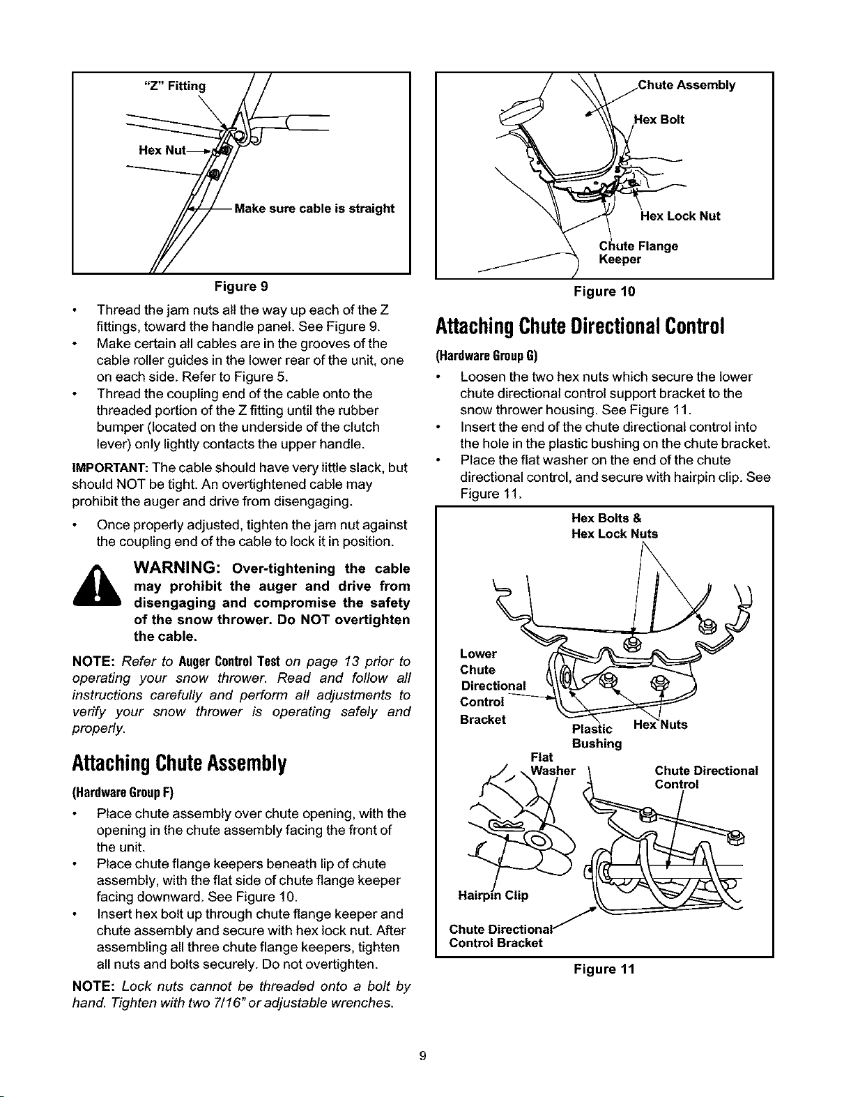
Chute Assembly
ck Nut
Figure 10
AttachingChuteDirectionalControl
(HardwareGroupG)
Loosen the two hex nuts which secure the lower
chute directional control support bracket to the
snow thrower housing. See Figure 11.
Insert the end of the chute directional control into
the hole inthe plastic bushing on the chute bracket.
Place the flat washer on the end of the chute
directional control, and secure with hairpin clip. See
Figure 11.
Hex Bolts &
Hex Lock Nuts
Lower
Chute
Directional
Control
Bracket
Plastic _uts
Bushing
Flat
Washer \ Chute Directional
i Clip
Chute DirectionaJ
Control Bracket
Figure 11
Loading ...
Loading ...
Loading ...