Loading ...
Loading ...
Loading ...
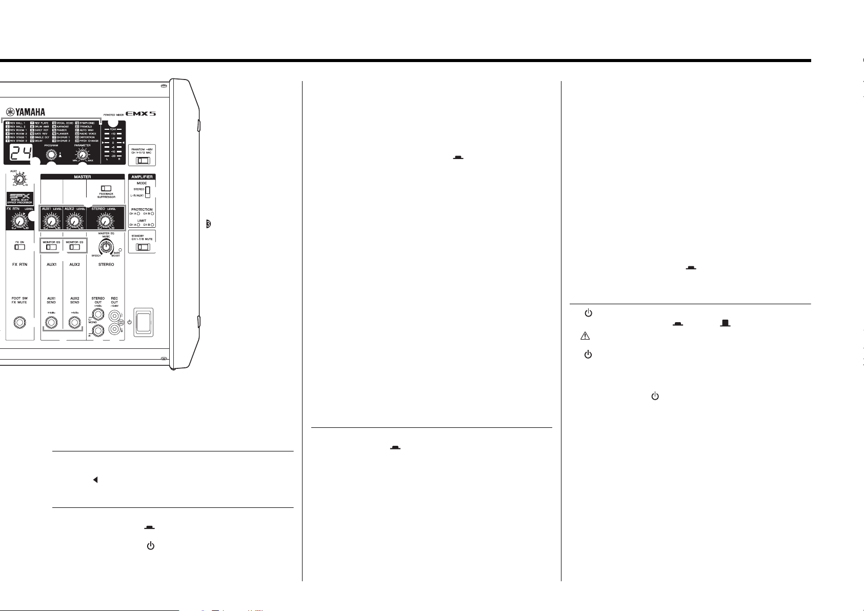
Controls and Functions
11
EMX5 Owner’s Manual
!9 Level meter
This uses LED indicators to show the STEREO L/R signal levels.
The “0” ( ) segment corresponds to the nominal output level. The
“PEAK” segment on the level meter lights up when output reaches
the clipping level.
@0 [FEEDBACK SUPPRESSOR] switch
When this switch is on ( ), it lights up to indicate that feedback is
automatically suppressed. (This utilizes a seven-band notch filter.
When this switch or the [ ] (Power) switch is off, the notch filter will
be reset.)
NOTE
When you change to a different effect type, the mixer automatically
restores the value that was previously used with the newly selected effect
(regardless of the current position of the [PARAMETER] control).
@1 AUX1 MASTER [LEVEL] control
AUX2 MASTER [LEVEL] control
STEREO MASTER [LEVEL] control
For adjusting the level of the signals sent to the AUX1, AUX2, and
STEREO L/R.
@2 [MONITOR EQ] switches
When connecting monitor speakers to the [AUX1 SEND]/[AUX2
SEND] jacks, turning this switch to on ( ) will cut the unnecessary
range to meet the sound quality suited to the monitor indication.
@3 [MASTER EQ] control
For adjusting the frequency balance of the overall sound. The center
position “MUSIC” is a basic setting and if you turn the control to the
left, this creates an optimum setting for speech, cutting unnecessary
low range audio frequencies. Turning the control to the right creates
an optimum setting for music, by boosting the low and high ranges.
Turning it further to the right creates an even more powerful bass
tone with the “BASS BOOST” indicator turning on to indicate that the
bass boost function is on.
@4 [AUX1 SEND] jack
[AUX2 SEND] jack
For connecting to a musician monitoring system, external effect
device, and so on. These are impedance balanced TRS phone type
output jacks. (See the “Jack and Plug List” on page 18.)
@5 [STEREO OUT] jacks
These are TRS phone type impedance balanced output jacks that
output the mixed stereo signal. The signal level is adjusted by the
STEREO MASTER [LEVEL] control before it is output. Using only
the [L/MONO] jack lets you obtain a signal composed of the left and
right channels mixed together.
@6 [REC OUT] jacks
These are unbalanced RCA-pin output jacks. They can be used to
connect an external recorder. The output signal from these jacks is
not affected by the STEREO MASTER [LEVEL] control. The record-
ing level can be separately adjusted on the recording device.
@7 [PHANTOM +48V] switch
Turn this switch on ( ) to supply all the XLR input jacks (channels
1 to 11/12) with DC +48 V phantom power. Turning on the switch
supplies power to condenser microphones or a DI (direct injection
box). When it is on, the switch lights up.
NOTICE
Follow the important precautions below, in order to prevent noise
and possible damage to external devices and the mixer when you
operate this switch.
• If you do not need phantom power, or when you connect a device
that does not support phantom power, be sure to leave this switch
off or connect via the phone (channels 1 to 7/8) / RCA-pin (9/10
and 11/12) / stereo mini (11/12) plugs.
• Do not connect or disconnect cables while this switch is on.
• Turn @1 AUX1, AUX2, and STEREO MASTER [LEVEL] controls to
the minimum setting before operating this switch.
@8 AMPLIFIER [MODE] switch
Determines which signal is output from the [SPEAKERS A/B] jacks:
STEREO bus or L+R/AUX1 bus.
@9 AMPLIFIER [PROTECTION] indicators
Lights up to indicate amplifier protection is operating. The “CH A”
indicator is for the signal sent to the [SPEAKERS A] jack. The “CH
B” indicator is for the signal sent to the [SPEAKERS B] jack.
#0 AMPLIFIER [LIMIT] indicators
These light up when the DSP amplifier protection limiter is operating.
The “CH A” indicator is for the signal sent to the [SPEAKERS A] jack.
The “CH B” indicator is for the signal sent to the [SPEAKERS B] jack.
#1 [STANDBY] switch
When this switch is turned on ( ), it lights up and all inputs for
channels 1 to 7/8 are muted. Please note that channels 9/10 and 11/
12 are not muted. This is an added convenience for playing back-
ground music during gaps in the performance.
#2 [ ] (Power) switch
For turning the power ON ( ) or OFF ( ).
#3 Vents
There are vents located on both sides of the mixer, and a cooling fan
is installed on the exhaust side. Do not block the vents on either side
when using the mixer.
NOTICE
If used at a very high volume such that the indicators flash continu-
ously, the internal power amplifier section will be excessively over-
loaded and may malfunction. Reduce the output level with the AUX1
and STEREO MASTER [LEVEL] controls so that the indicators flash
only briefly on the highest transient peaks.
WARNING
Please note that trace current can continue to flow even when the
[ ] (Power) switch is in the OFF position. If you do not plan to use
the mixer for an extended period of time, be sure to unplug the
power cord from the wall outlet.
NOTICE
Rapidly turning the [ ] (Power) switch on and off in succession
may cause it to malfunction. After turning the mixer OFF, wait for
about 10 seconds before turning it ON again.
@4
!5
@3
#2
!2
!3
!4
@1
@8
#1
!8
!9
!7
!6
!1
@0
@7
@6@5
#3
@2
@9
#0
Loading ...
Loading ...
Loading ...