Loading ...
Loading ...
Loading ...
10
EMX5 Owner’s Manual
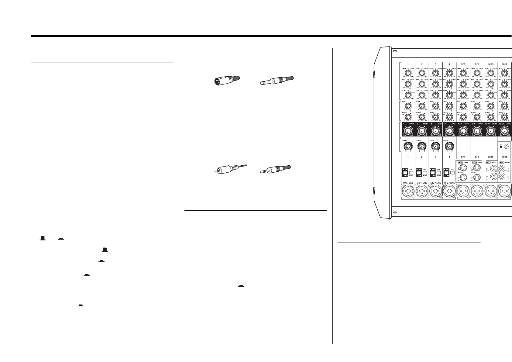
Controls and Functions
q Equalizer controls [HIGH]/[MID]/[LOW]
For adjusting the [HIGH], [MID], and [LOW] audio frequencies. Turn-
ing the control to the right amplifies (boosts) the corresponding fre-
quency band, while turning to the left attenuates (cuts) the band.
Setting the control to the “t” position produces a flat response in the
corresponding band.
w [AUX1] send controls (Channels 1 – 11/12)
[AUX2/FX] send controls (Channels 1 – 11/12)
For adjusting the levels of each signal sent to the AUX1 and AUX2/
FX (built-in effects) buses from each channel independently. On
channels 5/6 to 11/12, the Line L (odd) and Line R (even) input sig-
nals are mixed before being sent into the AUX1 and AUX2/FX buses.
Adjust the controls so that they are near the “t” (nominal) position.
e [LEVEL] controls (Channels 1 – 11/12)
For adjusting the volume for each channel. Set all [LEVEL] controls
on unused channels to the minimum in order to reduce noise.
r [COMP] controls
For adjusting the amount of compression applied to the correspond-
ing channel. As the [COMP] control is turned to the right, the thresh-
old, ratio, and output gain are adjusted simultaneously.
t [ MIC/ LINE] switches (Channels 1 – 4)
For channels with low-level input signal devices such as micro-
phones, set the switches to the “ MIC” position. For channels with
high-level input signals such as electronic instruments and audio
devices, set the switch to the “ LINE” position.
y [HPF] (High Pass Filter) switches (Channels 1 – 3)
Turning this switch on ( ) applies a high-pass filter that attenuates
frequencies below 80 Hz in the signal by a slope of 12 dB/octave.
This function should be kept on when using vocals in order to reduce
noise from vibration or wind picked up by the microphone.
u [Hi-Z] switch (Channel 4)
Turn this switch on ( ) when you wish to connect instruments with
passive pickups such as acoustic-electric guitars or electric bass
guitars that do not have internal batteries. It enables such devices to
be directly connected to the mixer without the need for a DI (direct
injection box). This function affects only the phone jack input.
Front Panel
NOTE
The [AUX1] send control is a PRE setting that is not affected by the
[LEVEL] control, and the [AUX2/FX] send control is a POST setting that is
affected by the [LEVEL] control.
NOTE
Avoid raising the level of the [COMP] control too high, as the higher aver-
age output level that results may lead to feedback.
i [MIC/LINE] input jacks (Channels 1 – 4)
For connecting microphones, guitars, electronic musical instruments
or audio devices. These are compatible with both XLR and phone
plugs.
o [MIC] input jacks (Channels 5/6, 7/8, 9/10, 11/12)
These are balanced XLR microphone input jacks.
!0 [LINE] input jacks (Channels 5/6, 7/8, 9/10, 11/12)
For connecting line-level devices such as electronic instruments,
acoustic-electric guitars, CD players, and portable audio players.
These are compatible with TS phone, RCA-pin, and stereo mini
plugs. Using only the [L/MONO] jacks results in the stereo left and
right channels outputting the same signal.
• Channels 5/6, 7/8: TS phone
• Channel 9/10: RCA-pin
• Channel 11/12: RCA-pin, stereo mini
!1 FX RTN (Effect Return) [AUX1] send control
For adjusting the level of the signal sent from the built-in effects to
the AUX1 bus.
!2 FX RTN [LEVEL] control
For adjusting the level of the effect sent from the built-in effects to the
STEREO L/R bus.
!3 FX RTN [FX ON] switch
For turning the corresponding built-in effects on or off. It lights up
when it is switched on ( ).
!4 FX RTN [FOOT SW] (Foot Switch) jack
For connecting an unlatched-type foot switch such as the Yamaha
FC5. It is useful for solo performers, since it allows you to mute the
effects with your foot.
NOTE
If desired, a single channel’s [MIC] and [LINE] jacks can be used together
at the same time. But note that the levels cannot be adjusted indepen-
dently. The stereo mini jack has priority for channel 11/12 [LINE] input jack.
NOTE
The FX RTN [LEVEL] control does not affect the level of the signal sent to
the AUX1 bus.
NOTE
If this switch is on and the foot switch (see “!4 FX RTN [FOOT SW] jack”)
is used to mute the built-in effects, the switch flashes.
XLR Phone
RCA-pin Stereo mini
!5 Effect program list
This is a convenient on-panel list of the built-in effect programs. For
details about these programs, see the “Effect Programs” on page 17.
!6 Display
Shows the currently used program and settings screens for each
function.
!7 [PROGRAM] rotary encoder
For selecting one of the 24 built-in effects. Turn the rotary encoder to
select the desired effect, and then press the encoder to enable it.
!8 [PARAMETER] control
For adjusting parameters (depth, speed, etc.) for the selected effect
program. The last value used with each effect program is saved.
NOTE
You can also select the desired effect by turning the rotary encoder while
holding it down.
q
w
r
i
ty u
o
e
ty ty t
#3
!0
Loading ...
Loading ...
Loading ...