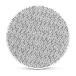
M3/M6-VEX™ - Enclosed Speaker Systems
with Integrated RGB LED Lighting (optional)
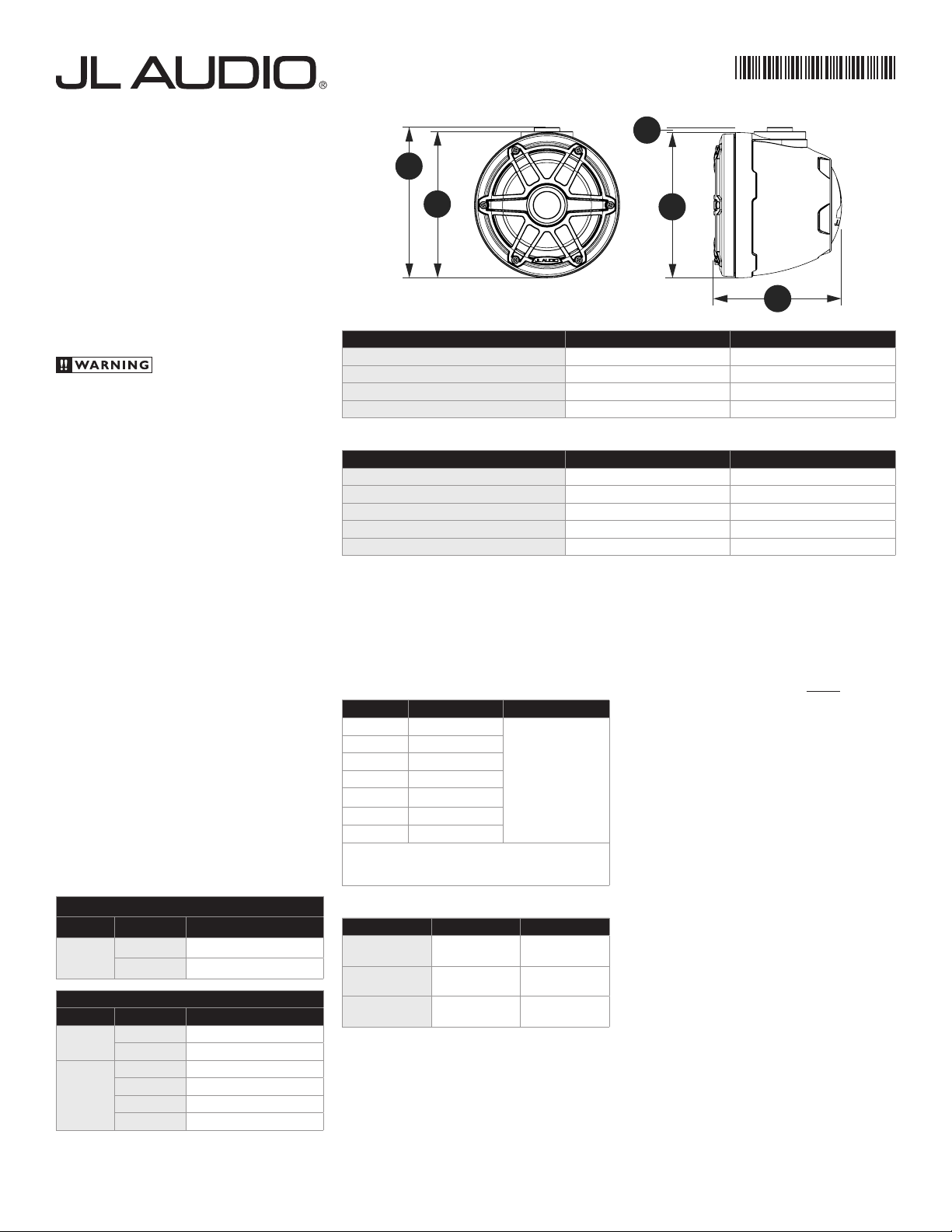
Physical Specifications M3-650VEX M6-650VEX
Enclosure Diameter (A)
7.03 in / 179 mm 7.03 in / 179 mm
Enclosure Depth (B)
6.16 in / 156 mm 6.17 in / 157 mm
Height including Mounting Fixture Receiver* (C)
7.27 in / 185 mm 7.27 in / 185 mm
Mounting Fixture Receiver / Enclosure Offset (D)
.20 in / 5 mm .20 in / 5 mm
*Mounting Fixtures Required (sold separately)
General Specifications M3-650VEX M6-650VEX
System Nominal Impedance
4 Ω 4 Ω
System Frequency Response
100 Hz - 25 KHz ± 3 dB 100 Hz - 25 KHz ± 3 dB
System Efficiency
89.5 dB @ 1 W / 1 m 89.5 dB @ 1 W / 1 m
Continuous RMS Power Handling (per Ch.)
60 W 75 W
Recommended RMS Amplifier Power (per Ch.)
20 - 120 W 25 - 150 W
Thank you for choosing JL Audio VEX™ Enclosed
Speaker Systems. With proper installation, your new
speakers will deliver years of listening pleasure.
We strongly recommend that you have your
Enclosed Speaker Systems installed by your
authorized JL Audio dealer. The installation
professionals employed by your dealer have the
necessary tools and experience to properly install
this product. If you prefer to perform your own
installation, please read this and the instructions
included with your Mounting Fixtures (sold
separately) completely before beginning the process.
Installation of this product requires use of
JL Audio® Mounting Fixtures (sold separately).
No other method of installation should be
attempted. To avoid injury, installation
instructions included with the JL Audio®.
Mounting Fixtures MUST be followed precisely.
Do not attempt to remove the LEDs from from
the speakers. The LEDs are permanently fixed and
attempting to remove them will cause damage and
this damage will not be covered under warranty.
LED EQUIPPED MODELS
Illuminated speaker models are outfitted with
multi-color RGB LEDs to produce vibrant accent
lighting. Refer to the Wiring Harness Info tables
below for individual wire connection info.
Note: Wiring connections for each speaker are
required for LED functionality.
Adjustable control of RGB lighting may be
achieved with the use of an RGB lighting control-
ler (sold separately). Note: When selecting an
RGB lighting controller, make sure that the total
amperage demands of all LED circuits does not
exceed the output capacity of the controller.
Refer to the RGB LED Specifications table for the
individual current draw amounts and sum (add)
the total. For optimal performance, we recom-
mend using the JL Audio marine lighting controller
(MLC-RW).
Wiring Harness Info
Models Without LEDs
Wire Size Wire Label Use
16 AWG
"+” Speaker Positive (+)
N/A
Speaker Negative (–)
Models With LEDs
Wire Size Wire Color Use
16 AWG
Red/Stripe Speaker Positive (+)
Black/Stripe
Speaker Negative (–)
20 AWG
Red Red RGB LED Negative (–)
Green Green RGB LED Negative (–)
Blue Blue RGB LED Negative (–)
Yellow Main RGB LED Positive (+12V)
DIRECT LED WIRING
Alternatively, you may hard wire individual leads
or a combination of leads to achieve up to seven
different LED color assortments. Refer to the table
below for the wire colors used to achieve specific
LED colors.
LED Color Wire Color(s) Connection
Red Red
Combine selected
wires from all
speakers and connect
to negative ground
or to the negative (–)
battery post.
Green Green
Blue Blue
Yellow Red and Green
Pink Red and Blue
Aqua Green and Blue
White Red, Green and Blue
Combine all YELLOW (+12V) leads together (parallel)
and connect to a switched +12V supply. See below for
additional info.
RGB LED Specifications
Specification M3-650VEX M6-650VEX
LED Current Draw
at 12V DC
108 mA 324 mA
Recommended
Fuse Value
150 mA 500 mA
LED Voltage
Range
10 - 14.4V DC 10 - 14.4V DC
LED WIRING CONSIDERATIONS
• Do not connect to 24V electrical systems.
• Do not connect the speakers’ LED lights to the
vessel’s navigational lighting circuits.
• For short-circuit protection, we recommend
installing a fuse (not included) at EACH speaker’s
YELLOW (+12V) LED power connection lead.
Refer to the RGB LED Specifications table for
recommended fuse ratings.
• We recommend a minimum of 16AWG wire size
for each speaker’s LED connection circuits.
• In addition to the above, we recommend
activating the speakers’ LEDs thru a cabin/
interior lighting circuit that supplies +12V via an
existing switch. If an existing switched circuit
is not available, you may install a dedicated
toggle/rocker style switch that will supply
positive (+12V) power. Fuse this main +12V
connection according to the total amperage
demands of all LED circuits. Refer to the RGB
LED Specifications table for individual current
draw amounts and recommended fuse ratings.
INCLUDED PARTS
• M3-650VEX
Two Lexan Logo Appliqués
• M6-650VEX
Two Aluminum Logo Caps
One Tube of Silicone Adhesive
M3-M6-VEX_071019_SKU#011523
A
C
B
A
D
NOTE: Illustration may not be to scale.
M6 Sport Grille shown.