Ol'qI 3t'O.
Contents
AV Receiver
Before using
2
TX-DS797
Instruction Manual
Facilities and connections 8
Setup and operation
26
Thank you for purchasing the Onkyo AV Recel\ el.
Please _ead tl'as manual thoroughly before making
connections and plugging m the nmt. Following the
instructions m tills manual will enable you to obtain
opnmum pelfomlance and hstenmg enjoyment flom
",'our new AV Recep,'el Please _etam this manual fo_
futme _eference
Remote controller 56
Appendix 71
WARNING:
TO REDUCE THE RISK OF FIRE OR ELECTRIC SHOCK,
DO NOT EXPOSE THIS APPLIANCE TO RAIN OR
MOISTURE.
CAUTION:
TO REDUCE THE RISK OF ELECTRIC SHOCK, DO NOT
REMOVE COVER (OR BACK). NO USER-SERVICEABLE
PARTS INSIDE. REFER SERVICING TO QUALIFIED
SERVICE PERSONNEL.
/_ WARNING AVIS
The lightning llash wi_h arrowhead symbol, within an equilateral
triangle, is intended to alert the user to _he presence of uninsulated
"dangerous voltage" within the product's enclosure that may be of
sufficient magnitude to constitute a risk of electric shock to persons.
The exclamation point within an equilateral triangle is intended to
//_ (servicing) instructions in the literature accompanying the appliance.
alert the user to the presence o4'important operating and maintenance
Important Safeguards
1. Read Instructions - All the safety and operating instructions
should be read before the appliance is operaled.
2. Retain Instructions - The safety and operating instructions
should he retained for future reference.
3. Heed Warnings - All warnings on the appliance and in the
operating instructions should be adhered to.
4. Follow Instructions - All operating and use instructions
should be followed.
5. Cleaning - Unplug the appliance from the wall outlet before
cleaning. The appliance should be cleaned only as recom-
mended by the manufacturer.
6. Attachments - Do not use attachments not recommended by
the appliance manufacturer as they may cause hazards.
7. Water and Moisture - Do not use the appliance near water -for
example, near a bath tub, wash bowl, kilchen sink, or laundry
tub; in a wet basement; or near a swimming pool; and the like.
8. Accessories - Do no4 place the appliance on an unstable cart,
stand, tripod, bracket, or table. The appliance may fall, causing
serious injury to a child or adult, and serious damage to the
appliance. Use only with a cart, stand, tripod, bracket, or table
recommended by the manufacturer, or sold with the appliance.
Any mounting of the appliance should follow the
manufacturer's instructions, and
should use a mounting accessory
recommended by the manufac-
turer.
9. An appliance and cart combina-
tion should be moved with care.
Quick stops, excessive force, and
uneven sm'faces may cause the
appliance and cart combination to
overturn.
PQRTABLECARTWARNING
S3125;A_
10. Ventilation - Slots and openings in the cabinet are provided
for ventilation and to ensure reliable operation of the appliance
and to protect it from overheating, and these openings must not
be blocked or covered. The openings should never be blocked
by placing the appliance on a bed, sofa, rug, or other similar
surface. The appliance should not be placed in a built-in instal-
lation such as a bookcase or rack unless proper ventilation is
provided. There should be free space of at least 20 cm (8 in.)
and an opening behind the appliance.
11. Power Sources - The appliance should be operated only from
the type of power source indicaled on the marking label. If you
are not sure of the type of power supply to your home, consult
your appliance dealer or local power company.
12. Grounding or Polarization - The appliance may be equipped
with a polarized alternating current line plug (a plug having one
blade wider than the other). This plug will fit inlo the power
outlet only one way. This is a safety feature. If you are unable 4o
insert the plug fully inlo the outlet, try reve_:sing the plug, If the
plug should still fail to fit, contact your electrician to replace
your obsolete outlet. Do not defeat the safety purpose of the
polarized plug.
13. Power-Cord Protection - Power-supply cords should be
routed so that they are not likely to be walked on or pinched by
items placed upon or against them, paying particular atlention
Io cords a4 plugs, convenience receptacles, and the point where
they exit from the appliance.
14. Outdoor Antenna Grounding - If an outside antenna or cable
system is connected to the appliance, be sure the anlenna or
cable system is grounded so as to provide some protection
against voltage surges and built-up static charges. Article 810
of the National Electrical Code, ANSUNFPA 70, provides in-
formation with regard 4o proper grounding of the mast and sup-
porting structure, grounding of the lead-in wire to an anlenna-
discharge unit, size of grounding conductors, location of an-
lenna-discharge unit, connection to grounding electrodes, and
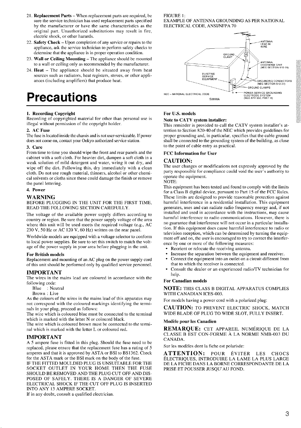
requirements for the grounding electrode. See Figure 1.
15. Lightning - For added protection for the appliance during a
lightning storm, or when it is left unattended and mmsed for
long periods of time, unplug it from the wall outlet and discon-
nect the anlenna or cable system. This will prevent damage to
the appliance due to lightning and power-line surges.
16. Power Lines - An outside antenna sys4em should not be lo-
cated in the vicinity of overhead power lines or other electric
light or power circuits, or where it can fall inlo such power lines
or circuits. When installing an outside anlenna system, extreme
care should be taken to keep from touching such power lines or
circuits as contact with them might be fatal.
17. Overloading - Do not overload wall outlets, extension cords,
or integral convenience receptacles as this can result in a risk
of fire or electric shock.
18. Object and Liquid Entry - Never push objects of any kind
into the appliance through openings as they may touch danger-
ous voltage points or short-out parts that could result in a fire or
electric shock. Never spill liquid of any kind on the appliance.
19. Servicing - Do no4 at4empt to service the appliance yourself as
opening or removing covers may expose you to dangerous volt-
age or other hazards. Refer all servicing to qualified service
personnel.
20. Damage Requiring Service - Unplug the appliance form the
wall outlet and refer servicing to qualified service personnel
under the following conditions:
A. When the power-supply cord or plug is damaged,
B. If liquid has been spilled, or objects have fallen into the
appliance,
C. If the appliance has been exposed to rain or waler,
D. If the appliance does no4 operate normally by following the
operating instructions. Adjust only those controls that are
covered by the operating instructions as an improper ad-
justment of other controls may result in damage and will
often require extensive work by a qualified technician to
restore the appliance to its normal operation,
E. If the appliance has been dropped or damaged in any way,
and
F. When the appliance exhibits a distinct change in perfor-
mance - this indicales a need for service.
2
21. Replacement Parts - When replacement parts are required, be
sure the service technician has used replacement parts specified
by the manufacturer or have the same characteristics as the
original part. Unauthorized substitutions may result in fire,
electric shock, or other hazards.
22. Safety Check - Upon completion of any service or repairs to the
appliance, ask 1heservice technician to perform safety checks Io
determine thai the appliance isin properoperation condition.
23. Wall or Ceiling Mounting - The appliance should be mounted
to a wall or ceiling only as recommended by the manufacturer.
24. Heat - The appliance should be situated away from heat
sources such as radiatons, heat registrars, stoves, or other appli-
ances (including amplifiers) that produce heat.
Precautions
FIGURE 1:
EXAMPLE OF ANTENNA GROUNDING AS PER NATIONAL
ELECTRICAL CODE, ANS I]NFPA 70
(N£C SECTION 8_0 20)
3ROUNDINGCQNDUCTORS
(N£OSECTIQN81021)
NEC NAT[ONALELECTRICALCOD£ £LECTRODESYSTE M
$2898A {N£C ART 250PART H}
1. Recording Copyright
Recording of copyrighted material for other than personal use is
illegal without permission of the copyright holder.
2. AC Fuse
Re fuse is located inside the chassis and is not u_r-serviceable. If power
does not come on, contact your Onkyo aulhodzed service station.
3. Care
From time to time you should wipe the front and rein" panels and the
cabinet with a soft cloth. For heavier dirt, dampen a sofi clolh in a
weak solution of mild detergent and water, wring it out dry, and
wipe off the dirt. Following this, dry immediately with a clean
cloth. Do not use rough material, thinne_s, alcohol or other chemi-
cal solvents or cloths since these could damage the finish or remove
the panel lettering.
4. Power
WARNING
BEFORE PLUGGING IN THE UNIT FOR THE FIRST TIME,
READ THE FOLLOWING SECTION CAREFULLY.
The voltage of the available power supply differs according to
country or region. Be sure that the power supply voltage of the area
where this unit will be used meets the required voltage (e.g., AC
230 V, 50 Hz or AC 120 V, 60 Hz) written on the rear panel.
Worldwide models are equipped with a voltage selector to conform
to local power supplies. Be sure 40 set this switeh to match the volt-
age of the power supply in your area before plugging in the unit.
For British models
Replacement and mounting of an AC plug on the power supply cord
of this unit should be performed only by qualified service personnel.
IMPORTANT
The wires in the mains lead are co[oured in accordance with the
following code:
Blue : Neutral
Brown : Live
As the colours of the wires in the mains lead of this apparatus may
not correspond with the coloured markings identifying the termi-
nals in your plug, proceed as follows:
The wire which is coloured blue must be connected to the terminal
which is marked with the letter N or coloured black.
The wire which is coloured brown must be connected to the termi-
nal which is marked with the letler L or coloured red.
IMPORTANT
A 5 ampere fuse is fitted in this plug. Should the fuse need to be
replaced, please ensure thai the replacement fuse has a rating of 5
amperes and thai it is approved by ASTA or BSI to BS 1362. Check
for the ASTA mark or the BSI mark on the body of the fuse.
IF THE FITTED MOULDED PLUG IS UNSUITABLE FOR THE
SOCKET OUTLET IN YOUR HOME THEN THE FUSE
SHOULD BE REMOVED AND THE PLUG CUT OFF AND DIS-
POSED OF SAFELY. THERE IS A DANGER OF SEVERE
ELECTRICAL SHOCK IF THE CUT OFF PLUG IS INSERTED
INTO ANY 13 AMPERE SOCKET.
If in any doubt, consult a qualified electrician.
For U.S. models
Note to CATV system installer:
This reminder is provided to call the CATV system installer's at-
tention to Section 820-40 of the NEC which provides guidelines for
proper grounding and, in particular, specifies that the cable ground
shall be connected to the grounding system of the building, as close
to the point of cable entry as practical.
FCC Information for User
CAUTION:
The user changes or modifications no1 expressly approved by the
party responsible for compliance could void the user's authority Io
operate the equipment.
NOTE:
This equipment has been tested and found to comply with the limits
for a Class B digital device, pursuant to Part 15 of the FCC Rules.
These limits are designed to provklc reasonable protection against
harmful interference in a residential installation. This equipment
generates, uses and can radiate radio frequency energy and, if not
installed and used in accordance with the instructions, may cause
harmful interference to radio communications. However, there is
no guarantee thai interference will no1occur in a particular installa-
tion. If this equipment does cause harmful inlerference to radio or
television reception, which can be determined by turning the equip-
ment off and on, the user is encouraged to try to correct the interfer-
ence by one or more of the following measures:
• Reorient or relocate the receiving antenna.
• Increase the separation between the equipment and receiver.
• Connect the equipment into an outlet on a circuit different from
that to which the receiver is connected.
• Consult the dealer or an experienced radio_V technician for
help.
For Canadian models
NOTE: THIS CLASS B DIGITAL APPARATUS COMPLIES
WITH CANADIAN ICES-003.
For models having a power cord with a polarized plug:
CAUTION: TO PREVENT ELECTRIC SHOCK, MATCH
WIDE BLADE OF PLUG TO WIDE SLOT, FULLY INSERT.
ModNe pour les Canadien
REMARQUE: CET APPAREIL NUMf_RIQUE DE LA
CLASSE B EST CON-FORME A LA NORME NMB-003 DU
CANADA.
Sur les modNes dont la fiche est polarisde:
ATTENTION: POUR I_VITER LES CHOCS
I_LECTRIQUES, INTRODUIRE LA LAME LA PLUS LARGE
DE LA FICHE DANS LA BORNE CORRESPONDANTE DE LA
PRISE ET POUSSER JUSQU'AU FOND.
3
Contents
I Before using
Important Safeguards ......................................... 2
Precautions ......................................................... 3
Contents .............................................................. 4
Features ............................................................... 6
Supplied accessories ......................................... 6
Before using this unit ......................................... 7
Setting the Voltage selector (Worldwide models only) ... 7
Installing the remote controller balteries ......................... 7
Using the remote controller.............................................. 7
I Facilities and connections
Front panel facilities ........................................... 8
Remote controller ............................................. 10
Rear panel facilities .......................................... 12
Connections ...................................................... 15
Connecting your audio components .............................. 15
Connectingyoorv,deocomponents..............................16
Connecting speakers ....................................... 19
Ideal speaker configuration ............................................ 19
Minimum speaker configuration for
surround sound playback ........................................ 19
Speaker placement .......................................................... 19
Connecting speakers ....................................................... 20
Connecting the speaker cable ......................................... 20
Connecting a subwoofer ................................................. 20
Connecting the remote zone (Zone 2)
speakers ....................................................... 21
When using the ZONE 2 OUT terminals ...................... 21
Operating components not reached by the
remote controller signals (IR IN/OUT) ....... 22
If the remote controller signal does not reach
the TX=DS797 remote sensor ................................. 22
If the remote controller signal does not reach
other components .................................................... 22
Connecting the power ...................................... 23
Connecting antennas ....................................... 24
Assembling the AM loop antenna .................................. 24
Connecting the AM antenna cable ................................. 24
Connecting the included antennas ................................. 24
Connecting an FM outdoor antenna ............................... 25
Connecting an AM outdoor antenna .............................. 25
Directional linkage ......................................................... 25
Connecting the antenna cable to the 751300 £1 antenna adapte •
(For all models other than European models) .............. 25
Setup and operation
Setup menus ..................................................... 26
Navigating through the Setup menu .............................. 27
Hardware Setup ................................................. 28
o. Hardware Setup menu ............................................. 28
O=1. Speaker Impedance sub-menu ................................ 28
0=2. IR IN Setup sub=menu ............................................ 28
0=3. AM Frequency Step sub-menu ............................... 28
Speaker Setup ................................................... 29
l. Speaker Setup menu................................................. 29
1=1. Speaker Config sub=menu ...................................... 29
1=2. Speaker Distance sub=menu .................................... 30
1=3. Level Calibration sub=menu ................................... 31
1=4. Bass Peak Level (Bass Peak Level Manager*)
sub-menu ................................................................. 32
Input Setup ........................................................ :33
2. Input Setup menu ..................................................... 33
2=1. Digital Setup sub=menu .......................................... 33
2=2. Mu[tichannel Setup sub=menu ................................ 34
2=3. Video Setup sub-menu ............................................ 35
2=4. Character Input sub=menu ...................................... 36
2=5. Inlelli Volume sub=menu ......................................... 36
2=6. Listening Mode Preset sub-menu ........................... 37
Audio Adjust ...................................................... 40
3. Audio Adjust Setup menu ........................................ 40
Preference ......................................................... 44
4. Preference menu ....................................................... 44
4=1. Volume Setup sub=menu ......................................... 44
4=2. Headphones Level Setup sub-menu ....................... 45
4=3. OSD Setup sub=menu .............................................. 45
4=4. OSD Position sub-menu ......................................... 45
Listening to Radio Broadcasts ........................ 46
Tuning into a radio station ............................................. 46
Lislening Io a stereo radio station (FM mode) .............. 46
Presetting a radio station ................................................ 47
Selecting a preset radio station ...................................... 47
Erasing a preset radio station ......................................... 47
Listening to RDS broadcasts
(European models only) .............................. 48
Listening to RDS broadcasts .......................................... 48
PTY program types in Europe ........................................ 48
Displaying Radio Text (RT) ........................................... 49
Performing a PTY scan .................................................. 49
Performing a TP scan ..................................................... 49
4
Contents
_N
N_
Ns
@
@
Enjoying music or videos with theTX-DS797 ... 50
Basic operation ............................................................... 50
Temporarily turning off 1he sound ..................................... 50
Adjusting the bass and treble ......................................... 50
Listening with heaflphones ............................................. 50
Changing the listening mode .......................................... 51
Enlering names for input sources and tuner stations ..... 51
Swilching the display ..................................................... 52
Adjusting the brightness of the front display ................ 52
Using the sleep time (remote controller only) ............... 52
Temporarily changing the speaker output levels ........... 52
Changing the audio mode ............................................... 53
Enjoying the multichannel output .................................. 53
Enjoying music in the remote zone ................ 54
Playing music using the buttons on the TX=DS797 ...... 54
Selecting an input source using the remote controller .. 54
Recording a source .......................................... 55
To record the input source signal
you are currently watching or listening to ............. 55
To record an input source signal different from
that you are currently watching or listening to ...... 55
I Remote controller
Using remote controller ................................... 56
Overview ........................................................................ 56
Calling up a preset radio station .................................... 56
Controlling an Onkyo cassette tape deck ...................... 56
Controlling an Onkyo CD player ................................... 57
Controlling an Onkyo DVD player ................................ 58
Controlling an Onkyo MD recorder ............................... 59
SAT, CABLE, VCR, and TV MODE buttons ................ 59
Learning a pre-programming code ................. 60
Learning a pre-programming code ................................. 60
Pre-programming codes ................................................. 61
Operating your programmed
remote controller ......................................... 62
DVD MODE (DVD Player Mode) ................................ 62
SAT MODE (Satellite Tuner Mode) .............................. 62
CABLE MODE (Cable Mode) ....................................... 62
VCR MODE (VCR Mode) ............................................. 63
TV MODE (TV Mode) ................................................... 63
Programming the commands of remote
controllers for other devices into the
remote controller ......................................... 64
Programming procedure ................................................. 64
Erasing the programmed command from one button .... 66
Erasing all the commands programmed
under a MODE button ............................................ 66
Using a Macro function .................................... 67
What is a Macro function? .......................................... 67
Programming a Macro function ..................................... 67
Running a Macro function ............................................. 67
Programming the Direct Macro function ....................... 68
Running a Direct Macro function .................................. 68
Erasing a macro from the MODE MACRO button ....... 69
Erasing a direct macro from lhe DIRECT MACRO button ..... 69
Erasing all commands and macros
thai have been programmed .................................... 70
(Macro mode programming memo ............................... 70)
I Apendix
Specifications ................................................... 71
Troubleshooting guide ..................................... 72
POWER .......................................................................... 72
SPEAKERS .................................................................... 72
FM/AM TUNER ............................................................. 72
VIDEO and AUDIO ....................................................... 73
REMOTE CONTROLLER ............................................ 73
OTHER ........................................................................... 73
If one of the messages shown below appears ................ 73
Declaration of Conformity
WeO YOOP
ELECTRONICS GmbH
INDUSTRIESTRASSE 20
82110 GERMERING,
GERMANY
declare in own responsibility, that the ONKYO product described
in this instruction manual is in compliance with the corresponding
lechnical standards such as EN60065, EN55013, EN55020 and
EN61000=3=2. -3=3. _,,/
GERMERING, GERMANY
ONKYO EUROPE ELECTRONICS GmbH
5
Features
Amplifier Features
• 100 W×2 (Front)/100 W (Center)/100 W×2
(Surround)/100 W (Surround Back) at 8 _,
20Hz-20kHz, 0.08% THD (FTC)
• 135 Wx2 (Front)/135 W (Center)/135 Wx2
(Surround)/135 W (Surround Back) at 6 _ (DIN)
• 160 Wx2 (Front)/160 W(Center)/160 Wx2
(Surround)/160 W (Surround Back) at 6 _ (EIAJ)
• 6 Channel Amplifier
• Wide Range Amplifier Technology (WRAT)
• Linear Optimum Gain Volume Circuitry
• 192 kHz/24 Bit D/A Converters (except for
Surround Back L/R)
• Ready for HDTV, Progressive-Scan DVD
and DVD-Audio
• Zone-2 Capability
Audio/Video Features
• THX ® Surround EX ®
• THX Select Certified
• Dolby _ Digital, Dolby Pro Logic II
• DTS, DTS-ES Discrete 6.1, DTS-ES Matrix
6.1 and DTS Neo:6
• Theater-DimensionaF MVirtual Surround
Mode
• Non-Scaling Configuration
• Onscreen displays (Basic menu/Advanced
menu)
• 2 Wideband Component-Video Inputs/1
Output
• Composite to S-Video Conversion
• 6 S-Video Inputs/3 Outputs
• 6 Assignable Digital Inputs (3 optical/3
coaxial), 1 outputs, and 1 Digital Input
(optical)
• Pre Out Terminals for Front L/R, Center,
Surround L/R, Surround back L/R and
Subwoofer
FM/AM Tuner Features
• 40 FM/AM random presets
• FM auto tuning
• RDS (European models only) with PS, PTY,
RT, TP
Other Performance Features
• IntelliVolume
• Character Input
• Powerful backlit/preprogrammed learning
remote with macro and mode-key LEDs
* Man ufactured under license fi'om Dolby Laboratories.
"Dolby," "Pro Logic," "Surround EX" and the double-D symbol are
trademarks of Dolby Laboratories.
• "TheatebDimensional" is a eademark of Onkyo Corporation.
• Lucasfilm and THX are trademarks of Lucasfilm Ltd. Al! rights
reserved. Used under authorization.
• Re-Equalization and the "Re-EQ" logo are trademarks of Lucasfilm Ltd.
Manufactured under license of Lucasfilm Ltd.
• "DTS," "DTS-ES Extended Surround" and "Neo:6" are trademarks of
Digital Theater Systems, Inc.
• Xantech is a registered trademark of Xantech Corporation.
• Niles is a registered trademark of Niles Audio Corporation.
THX Select
Before any home theatre component can be THX Select
certified, it must pass a rigorous series of quality and
performance tests. Only then can a product feature the THX
Select logo, which is your guarantee thai the Home Theatre
products you purchase will give you superb performance for
many years to come. THX Select requirements define
hundreds of parameters, including power amplifier
performance, and pre-amplifier performance and operalion
for both digital and analog domains. THX Select receivers
also feature proprietary THX technologies (e.g., THX Mode,
see page 39) which accurately translate film soundtracks for
home theater playback.
Supplied accessories
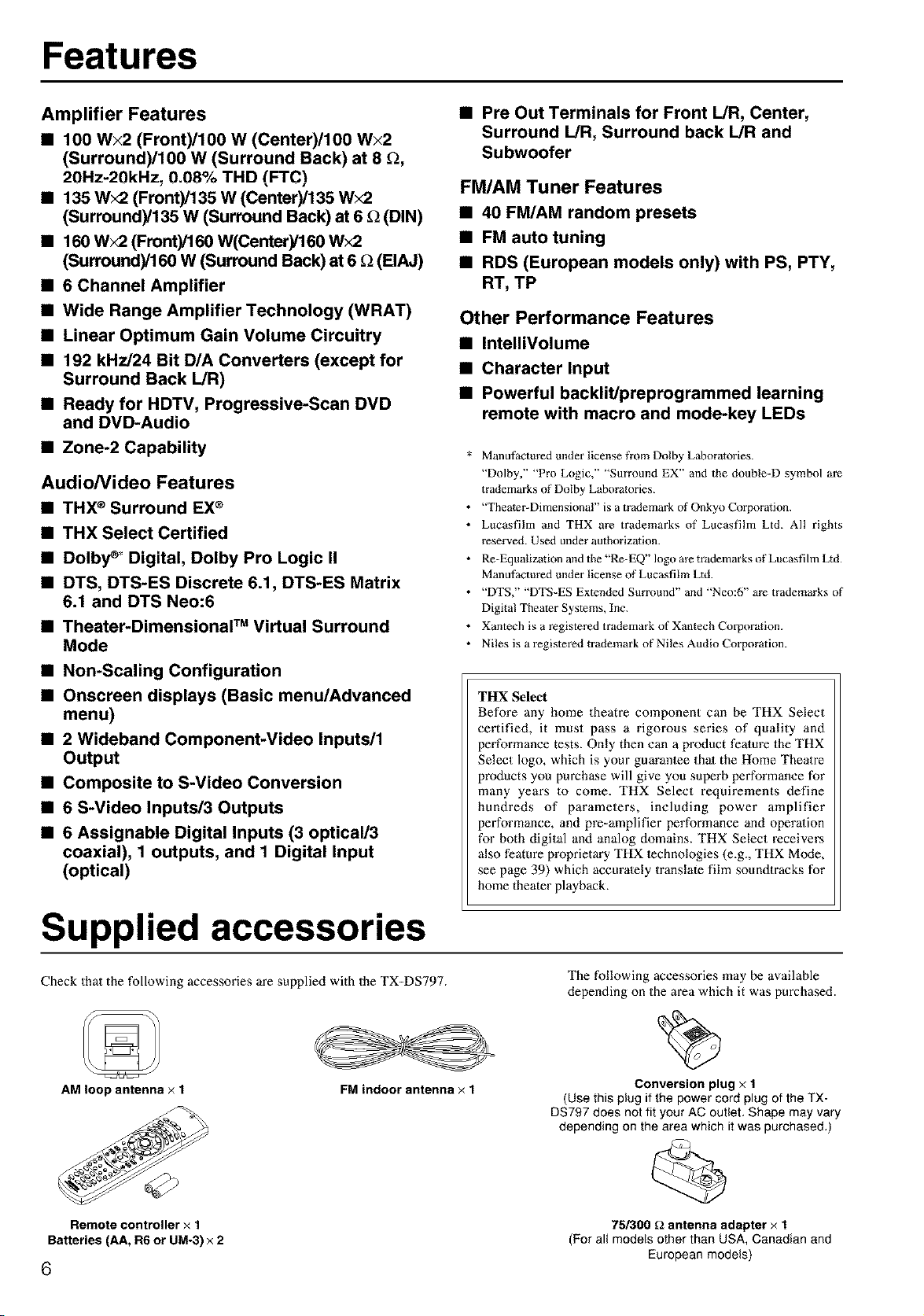
Check that the following accessories are supplied with the TX-DS797.
AM loop antenna x 1
FM indoor antenna × 1
The following accessories may be available
depending on the area which it was purchased.
Conversion plug x 1
(Use this plug if the power cord plug of the TX-
D8797 does not fit your AC outlet, Shape may vary
depending on the area which it was purchased.)
Remote controller x 1 75/300 _ antenna adapter × 1
Batteries (AA, R6 or UM-3) x 2 (For all models other than USA, Canadian and
European models)
6
Before using this unit
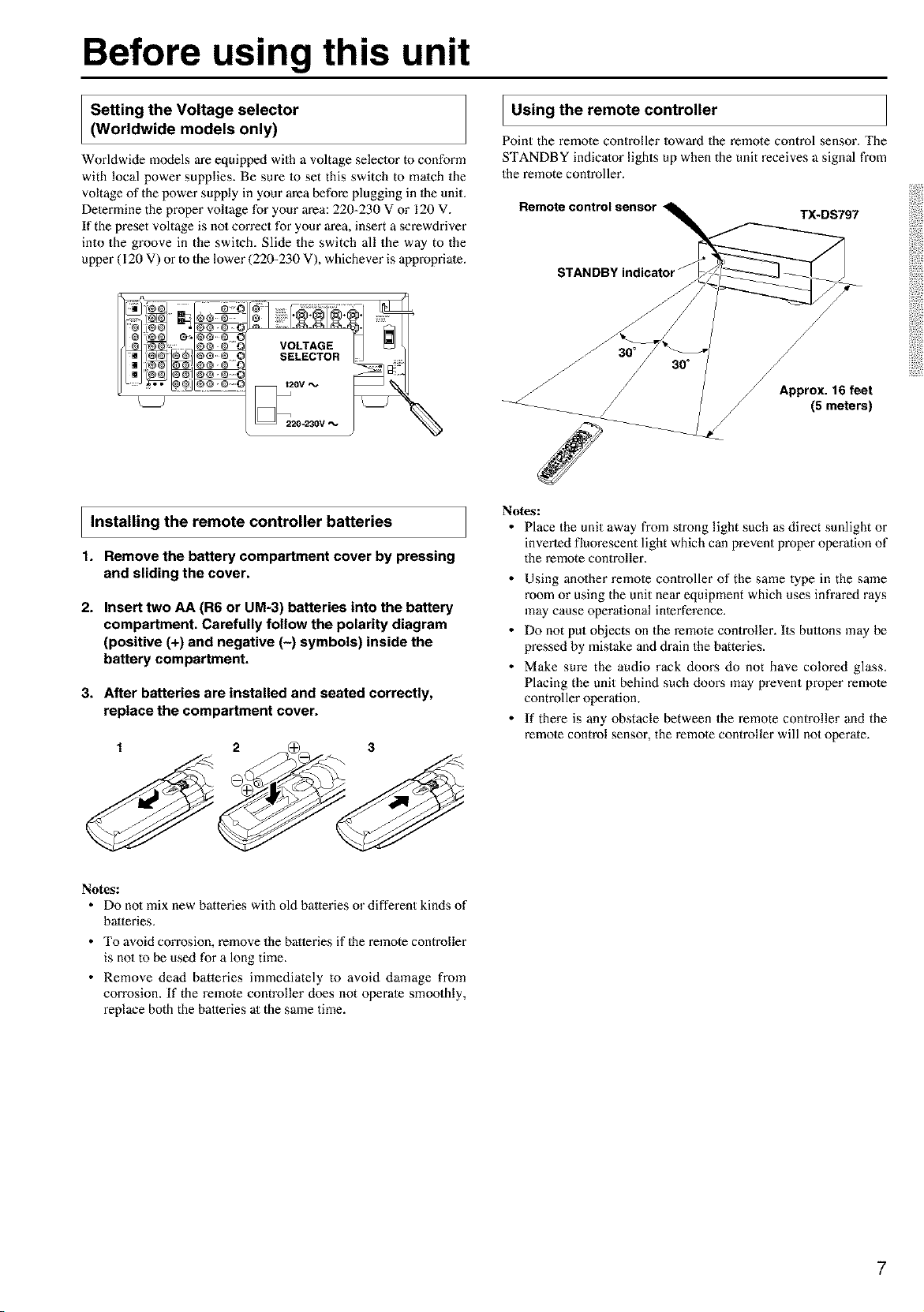
Setting the Voltage selector
(Worldwide models only)
Worldwide models are equipped with a voltage selector m conform
with local power supplies. Be sure 1o set this switch to match the
voltage of the power supply in your area before plugging in the unit.
Determine the proper voltage for your area: 220-230 V or 120 V.
If the preset voltage is no1 con'ect for your area, insert a screwdriver
into the groove in the switch. Slide the switch all the way to the
upper (120 V) or to the lower (220-230 V), whichever is appropriate.
I Using the remote controller
Point the remote controller Ioward the remote control sensor. The
STANDBY indicator lights up when the unit receives a signal from
the remote controller.
Remote control sensor
TX-DS797
STANDBY indicator J
VOLTAGE
SELECTOR
J
Approx. 16 feet
(5 meters)
I Installing the remote controller batteries
1. Remove the battery compartment cover by pressing
and sliding the cover,
2. Insert two AA (R6 or UM-3) batteries into the battery
compartment. Carefully follow the polarity diagram
(positive (+) and negative (-) symbols) inside the
battery compartment.
3. After batteries are installed and seated correctly,
replace the compartment cover.
Notes:
• Place the unit away from slrong light such as direct sunlight or
inverted fluorescent light which can prevent proper operation of
the remote controller.
• Using anolher remote controller of the same type in the same
room or using the unit near equipment which uses infrared rays
may cause operaliona[ interference.
• Do not put objects on the remote controller. Its buttons may be
pressed by mistake and drain the batteries.
• Make sure the audio rack doors do not have colored glass,
Placing the unit behind such dooz:s may prevent proper remote
controller operation.
• If there is any obstacle between the remote controller and the
remote control sensor, the remote controller will not operate.
Notes:
• Do no1mix new batteries with old batteries or different kinds of
batteries.
• To avoid corrosion, remove the batteries if 1he remote controller
is no1to be used for a long time.
• Remove dead batleries immediately to avoid damage from
corrosion. If the remote controller does not operate smoothly,
replace both the halteries at the same time.
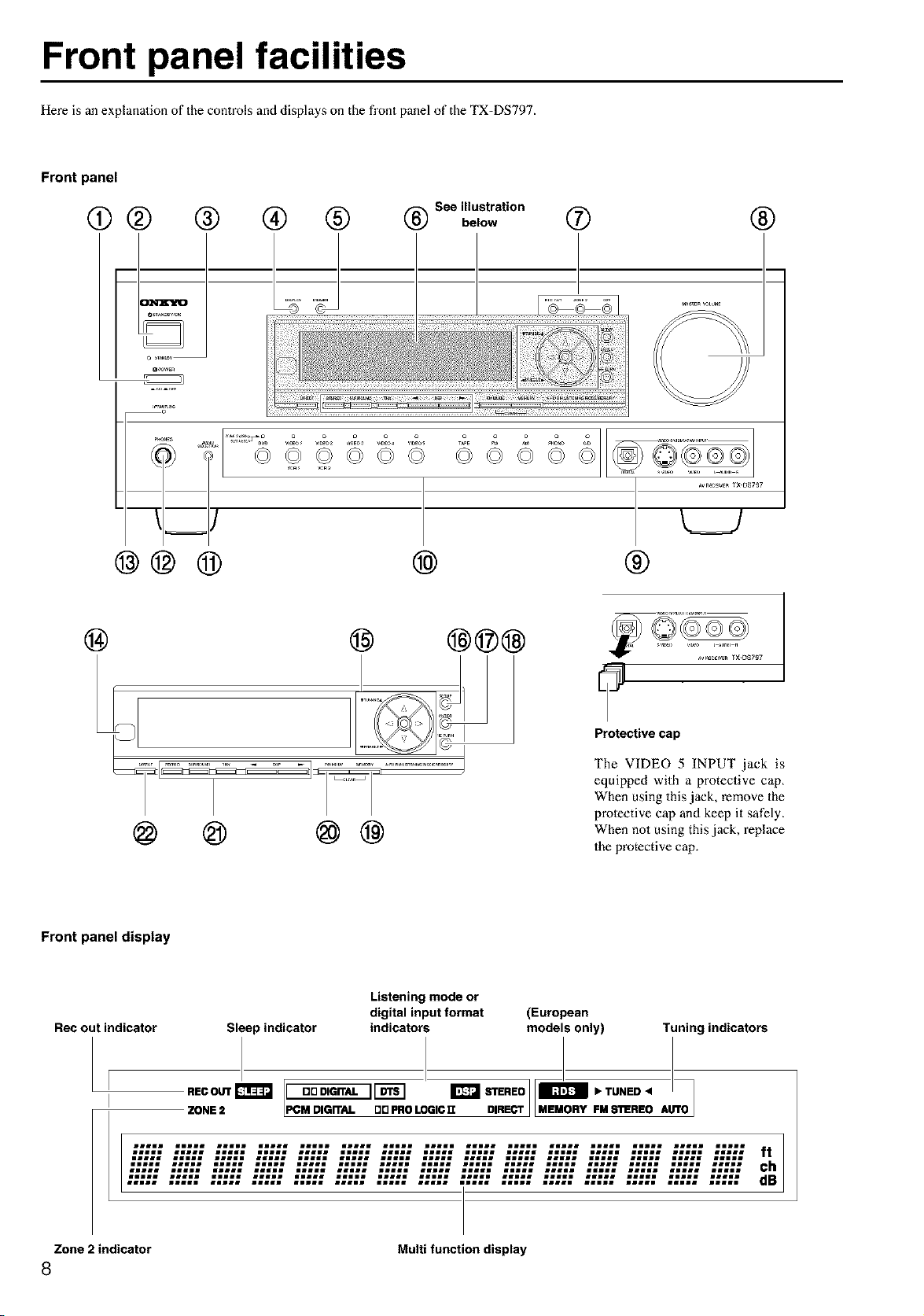
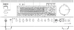
Front panel facilities
Here is an explanation of the controls and displays on the fl'ont panel of the TX-DS797.
Front panel
o
See illustration
@ @ below ® ®
m
P_s
@@@
..... _ o o o
©©©© ©© ©©
@
®
@ @ @@
@ @@@ _©_
7
Protective cap
The VIDEO 5 INPUT jack is
equipped with a protective cap,
When using this jack, remove the
proleetive cap and keep it safely.
When not using this jack, replace
the protective cap.
Front panel display
Rec out indicator
Sleep indicator
Listening mode or
digital input format (European
indicators models only) Tuning indicators
RECOUTr_J I DDDIGITAL IIDTSl _ STEREOJID IbTUNED4
ZONE 2 PCM DIGn'AL DD PRO LOGIC 1I DIRECT FM s'n!REO AUTO
ilill lille lilll illil lilJl illil illll Jlill iiJll ilill lille ilill lille ilill lille
Zone 2 indicator Multi function display
8

Front panel facilities
For operational instructions, see page indicated in brackets [ ].
@ POWER switch [23]
Turns on and off the main power supply for the TX-DS797.
@ STANDBY/ON button [23]
When this button is pressed with the main power switch tin'ned on,
the TX=DS797 turns on and the display lights up. Press again to
return the TX=DS797 to the standby state.
@ STANDBY indicator [7, 23]
Lights when the TX=DS797 is in the standby state and flashes when
a signal is received from the remote controller.
@ DISPLAY button [52]
The DISPLAY button is used to display information about the
current input source signal. Each time you press the display button,
the screen changes to show you different information concerning the
input signal.
@ RT/PTY/TP (European models only) button [49]
This button is only available on European models. Use this button to
help tune into the Radio Data System (RDS) for FM broadcasting.
RDS was developed within the European Broadcasting Union
(EBU) and is available in most European countries. Each time the
button is pressed, the display changes from RT (radio text) to PTY
(program type) to TP (traffic program) and then back to RT again.
®
DIMMER button [52]
Press 1o set the brightness of the fi'ont display. There are 3 settings
available: normal, dark, and very dark.
• The dimmer control for the fi'ont display can be performed at the
remote controller.
(_ Front display
REC OUT/ZONE ?-/OFF buttons [54, 55]
These buttons allow you to use the TX-DS797 to oulput 1o a remote
zone (Zone 2) or to anolher component for recording purposes tRee
Out). Press the REC OUT button to output the audio and video
signals Io a recording component for recording purposes. Press the
ZONE 2 button to enjoy the oulput from the TX=DS797 in a different
room, which is referred to as a remote zone (Zone 2).
When either bulton is pressed, the currently selected input source for
recording or outputting to the remote zone is displayed in the front
panel display. If "SOURCE" is displayed, then the same input
source as that selected for the main zone will be oulput.
To select an input source, press the desired button (REC OUT or
ZONE 2) and then press one of the input source button within 5
seconds. That source will be output for recording or viewing in the
remote zone.
"I_ set the REC OUT or ZONE 2 output to the source channel, press
that button twice in succession. "I_ turn off the REC OUT or ZONE
2 oulput, press that bulton and then press the OFF button within 5
seconds.
Note:
The Rec Out and Zone 2 buttons use the same circuit and therefore
cannol be used at the same time. When Rec Out is selected, nolhing
is oulput to Zone 2, and vice versa. When ZONE 2 is selected, REC
OUT is automatically fixed to SOURCE.
MASTER VOLUME dial [50, 53]
The MASTER VOLUME dial is used to control the volume for the
main zone. The volume for the remote zone (Zone 2) is independent.
@ VIDEO 5/VIDEO CAM INPUT terminals It8]
For connecting a video camera or game device.
(_) Input source buttons (DVD, VIDEO 1-5, TAPE, FM,
AM, PHONO, and CD) [23, 46, 50, 55]
These buttons are used to select the input source for the main zone.
To select the input source for the remote zone (Zone 2) or recording
out (Rec Out), first press the ZONE 2 or REC OUT bulton, and then
the desired input source button. The input channel with its indicator
lit red is output to REC OUT and the one with its indicator lit green is
oulput to ZONE 2.
AUDIO SELECTOR button [53]
This bulton is used to select the type of audio input signal. Each time
pressed, the setting cycles from "Aulo" --_ "Multich" --_ "Analog"
and back. When multichannel is no1 selected, the setting just changes
back and forth between "Auto" and "Analog."
(_ PHONES jack [501
This is a standard stereo jack for connecting storeo headphones.
(_ UPSAMPLING indicator [40]
Lights during upsampling. This function is available when the input
source is Analog/PCM and the listening mode is set to the storeo or
surround (Dolby Pro Logic II only) mode.
(_ Remote control sensor [7]
(_) TUNING &/T, PRESET ,<!/1_,cursor (,<!/I_/A/T)
buttons [27, 46, 47]
To tune in a radio station, use the &/V buttons. The tuner frequency
is displayed in the front display and it can be changed in 50 kHz
increments for FM and 10 kHz increments for AM.
When FM is selected, you can hold down one of the tuning buttons
and then release it to activate the auto=search feature. It will search
for a station in the direction of the button you pressed and stop when
it tunes into one. When navigating through the menu settings, these
buttons move the cursor up or down (or change the highlighted
item).
To select a radio station that was stored using the MEMORY button,
use the ,4/_" buttons.
When navigating through the menu settings, these buttons select the
value or item thai you selected with the TUNING A/V buttons.
When you press the SETUP button, the cm_sor indieatoz_s light and
the SETUP button becomes able to be used for setup menu
operations.
(_ SETUP button [27]
Press to enter the setup menu. When pressed, the cursor (_I/,/&/V)
indicators light. The OSD menu will appear on the TV monitor as
well as the front display on the TX=DS797.
(_ ENTER button[2_
Press to display the screen for the selected item in the Setup Menu.
9
Front panel facilities
RETURN button [27]
Press to exit the Main menu level or go back one level up.
MEMORY button [47]
This button is used to assign the radio station that is currently tuned
in Io a preset channel or delete a previously preset station.
FM MODE button [46]
If you are listening to an FM radio stalion in slereo and the sound
cuts out or there is a great deal of noise, switch from STEREO to
MONO. Each time this bulton is pressed, the AUTO indicalion turns
on and off, and the stereo mode changes from AUTO to MONO and
vice vei\qa.
(_ LISTENING MODE buttons [51]
Press these buttons to select a listening mode for the current input
source,
STEREO: Selects for normal stereo oulput.
SURROUND: Selects for the Dolby Pro Logic, Neo:6, Dolby
Digital, or DTS listening modes.
THX: Selects for the THX lislening mode.
DSP ,,</l_: Switehes to the listening mode before or after 1he cmTent
one.
DIRECT button [51]
The direct mode outputs the sound without sound adjustment or
filtralion. In the direct mode, even if the Subwoofer selling of the
Speaker Config sub-menu is set Io "Yes," no sound is output from
the subwoofer and the lefl and right channels are output, as is, to the
lefl and right speakers. Even for multichannel input signals, the
sounds are not passed through the sound adjustment cimuits.
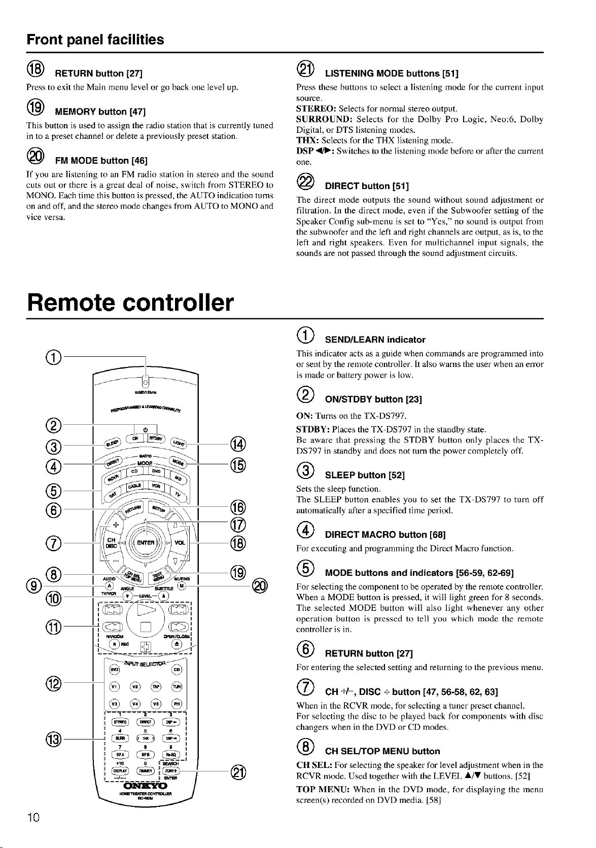
Remote controller
® I I
', ,-
@
@
10
@
SEND/LEARN indicator
This indicator acts as a guide when commands are programmed into
or sent by the remote controller. It also warns the user when an en'or
is made or battery power is low.
ON/STDBY button [23]
ON: Turns on the TX-DS797.
STDBY: Places the TX-DS797 in the standby state.
Be aware that pressing the STDBY butlon only places the TX-
DS797 in standby and does not turn the power completely oft'.
SLEEP button [52]
Sets the sleep function.
The SLEEP button enables you to set the TX-DS797 to turn off
automatically after a specified time period.
@ DIRECT MACRO button [68]
For executing and programming the Direct Macro function.
MODE buttons and indicators [56-59, 62-69]
For selecting the component to be operated by the remote controller.
When a MODE bullon is pressed, it will light green for 8 seconds.
The selected MODE button will also light whenever any other
operation button is pressed to tell you which mode the remote
controller is in.
RETURN button [27]
_ _mJvSELF__'_a_
4 5 e U
7 8 g U
/
@
For entering the selected setting and returning to the previous menu.
CH +1% DISC + button [47, 56-58, 62, 63]
When in the RCVR mode, for selecting a tuner preset channel.
For selecting the disc to be played back for components with disc
changers when in the DVD or CD modes.
CH SEUTOP MENU button
CH SEL: For selecting Ihe speaker for level adjustment when in the
RCVR mode. Used together with the LEVEL lk/V bultons. [52_
TOP MENU: When in the DVD mode, for displaying the menu
screen(s) recorded on DVD media. [581
Remote controller
@ AUDIO/TV/VCR button
AUDIO/A: For selecting the audio input signal. The setting changes
from "Auto" to "Multich" to "Analog" and back each time this
button is pressed. [531
TV/VCR: Must be preprograinmed for use in the TV and VCR
modes. [631
(_ LEVEL T/ANGLE and LEVEL A/SUBTITLE buttons
LEYEL •/A: Select the speaker whose volume is lo be adjusled
using Ihe CH SEL button and adjust the volume using the LEVEL A/
• buttons in the RCVR inode. [521
ANGLE: When in the DVD mode, for selecting a camera angle
when a DVD-Video is recorded with multiple angle playback. [581
SUBTITLE: When in the DVD mode, for selecting one of the
subtitle languages recorded on a DVD-Video. [58]
(_ CD/TAPE/DVD/MD operation buttons [56-59]
For operating other ONKYO components connected to the TX-
DS797 through the r.l I lerminals.
INPUT SELECTOR buttons [50]
Selects an input source.
Same as the input selecior buttons on front panel of the TX-DS797.
The input source for each buttons is given here. DVD:DVD, CD:CD,
VI:VIDEOI, V2:VIDEO2, V3:VIDEO3, V4:VIDEO4,
V5:VIDEO5, TAP:TAPE, TUN:FM/AM, PH:PHONO.
Numeric key/Listening mode SP A, B/
Re-EQ/DISPLAY/DIMMER buttons
1 to 9, +10, --/---, 0: For entering the number of a track. [57-63[
STEREO, DIRECT, DSP <1, SURR, THX: You can select a
listening mode. 151]
SP A, SP B: Not used with the TX-DS797.
Re-EQ: Depending on the listening mode, you can turn the cinema
re-equalizalion function on or oft'. 140, 43]
DISPLAY: For changing the display in the front display. [521
DIMMER: Adjusts the display brightness.
There are three settings available: normal, dark and very dark. [521
LIGHT button
For illuminaling the buttons of the remote controller.
This button is useful when using the remote controller in dark
locations. When pressed, the buttons on the remote controller light
green.
The button for the mode currently selecled lights brighter than the
rest.
MODE MACRO button [67]
For executing and programming the Macro function.
SETUP button [27]
For displaying and quitting the Setup menu.
(_) A/T/,</I_, ENTER button [27]
When selecting ilems in the Setup menu, press the upper and lower
portions to select an ilem, press the right and lefi portions to select
pm'ameter values or modes, and press ENTER Io select the item.
(_ VOL _ button [50, 53]
For adjusting the volume.
(_ TEST/MENU button
TEST: Outputs a test tone for setting speaker levels.
Use this butlon in conjunction with the LEVEL i/• and CH SEL
buttons to calibrate the speakers levels without entering the Setup
menu. When TEST button is pressed, the lest noise (pink noise) is
output. Use the LEVEL A/• buttons lo increase or decrease the
sound level. Use the CH SEL bution lo change from speaker to
speaker. For a more detailed explanation of how to calibrate the
speaker levels, see page 31.
MENU: When in the DVD mode, this button displays the DVD
menu. [581
MUTING button [50]
Activates the mute function.
(_ ZONE 2/SEARCH/ENTER button
ZONE 2: When in the RCVR mode, press this button to perform
operations on the remote zone (Zone 2). [54]
SEARCH: When in the DVD mode, for finding the specific section
on a disc where you want to start playback. [58]
ENTER: When in the MD mode, for confirming the selection. [59]
11
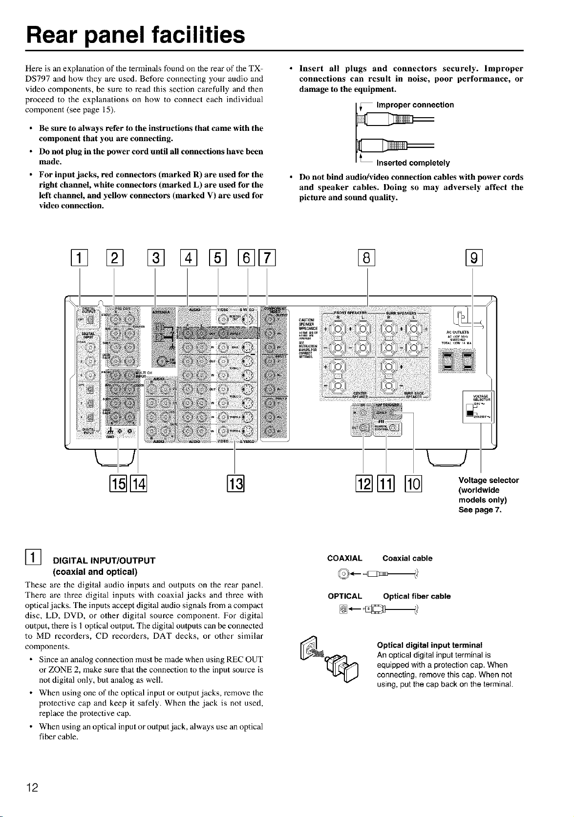
Rear panel facilities
Here is an explanalion of the lerminals found on the rear of the TX-
DS797 and how they are used. Before connecting your audio and
video components, be sure to read this section carefully and then
proceed to the explanations on how to connect each individual
component (see page 15).
• Be sure to always refer to the instructions that came with the
component that you are connecting.
• Do not plug in the power cord until all connections have been
made.
• For input jacks, red connectors (marked R) are used for the
right channel, white connectors (marked L) are used for the
left channel, and yellow connectors (marked V) are used for
video connection.
• Insert all plugs and connectors securely. Improper
connections can result in noise, poor performance, or
damage to the equipment.
• Do not bind audio/video connection cables with power cords
and speaker cables. Doing so may adversely affect the
picture and sound quality.
[] [] [] [] []
@@ @ @[]%
Voltage selector
(worldwide
models only)
See page 7.
] DIGITAL INPUT/OUTPUT
(coaxial and optical)
These are the digital audio inputs anti outputs on the rear panel
There are three digital inputs with coaxial jacks and three with
oplical jacks. The inputs accept digital audio signals from a compact
disc, LD, DVD, or other digital source component. For digital
oulpuL there is l optical output. The digital oulputs can be connecled
to MD recorders, CD recorders, DAT decks, or other similar
components.
• Since an analog connection must be made when using REC OUT
or ZONE 2, make sure 1hat the connection to the input source is
not digital only, but analog as well.
• When using one of the optical input or output jacks, remove the
prolective cap and keep it safely. When the jack is not used,
replace the prolective cap.
• When using an optical input or output jack, always use an optical
fiber cable.
COAXIAL
OPTICAL
Coaxial cable
Optical fiber cable
Optical digital input terminal
An optical digital input terminal is
equipped with a protection cap. When
connecting, remove this cap. When not
using, put the cap back on the terminal
12
Rear panel facilities
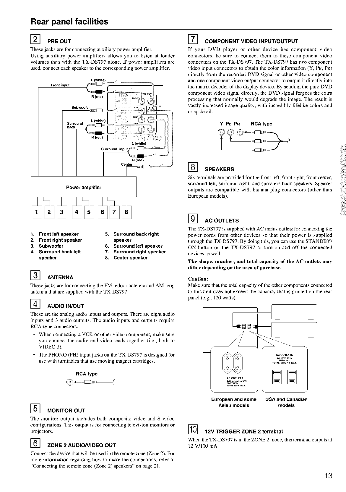
] PRE OUT
These jacks are for connecting auxiliary power amplifier.
Using auxiliary power amplifiers allows you to lislen at louder
volumes than with the TX=DS797 alone. If power amplifiez_s are
used, connect each speaker to the corresponding power amplifier.
Front input
R (red)
Subwooter
Surround
back
R (red)
Power amplifier
1. Front left speaker
2. Front right speaker
3. Subwoofer
4. Surround back left
speaker
5. Surround hack right
speaker
6. Surround left speaker
7. Surround right speaker
8. Center speaker
] ANTENNA
These jacks are for connecting the FM indoor antenna and AM loop
antenna that are supplied with the TX=DS797.
] AUDIO IN/OUT
These are the analog audio inpels and oulputs. There are eight audio
inputs and 3 audio outputs. The audio inputs and outputs require
RCA-type connectoz_s.
• When connecting a VCR or olher video component, make sure
you connect the audio and video leads together (Le., both to
VIDEO 3).
• The PHONO (PH) inpet jacks on 1he TX-DS797 is designed for
use with turntables that use moving magnet cm_tridges.
RCA type
] MONITOR OUT
The monitor output includes both composite video and S video
configurations. This oulput is for connecting television monitors or
projectors.
] ZONE 2 AUDIO/VIDEO OUT
Connect the device that will be used in the remote zone (Zone 2). For
more information regarding how 1o make the connections, refer to
"Connecting the remote zone (Zone 2) speakers" on page 21.
] COMPONENT VIDEO INPUT/OUTPUT
If your DVD player or other device has component video
connectors, be sure to connect them to these component video
connectors on the TX=DS797. The TX-DS797 has two component
video input connectoz_s to obtain the color information (Y, PB, PR)
directly from the recorded DVD signal or other video component
and one component video output connector to output it directly into
the matrix decoder of the display device. By sending the pure DVD
component video signal directly, the DVD signal forgoes the extra
processing that normally would degrade the image. The result is
vastly increased image quality, with incredibly lifelike co[oz_s and
crisp detail.
Y PB PR RCA type
] SPEAKERS
Six terminals m'e provided for the front left, front right, front center,
surround left, surround right, and surround back speakers. Speaker
outputs are compatible with banana plug connectors (other than
European models).
] ACOUTLETS
The TX=DS797 is supplied with AC mains outlets for connecting the
power cords from other devices so that their power is supplied
through the TX=DS797. By doing this, you can use the STANDBY/
ON button on the TX=DS797 to turn on and off the connected
devices as well.
The shape, number, and total capacity of the AC outlets may
differ depending on the area of purchase.
Caution:
Make sure that the total capacity of the other components connected
to this unit does not exceed the capacity that is printed on the rear
panel (e.g., 120 watts).
European and some USA and Canadian
Asian models models
] 12V TRIGGER ZONE 2 terminal
When the TX-DS797 is in the ZONE 2 mode, this terminal outputs at
12 V/100 mA.
13
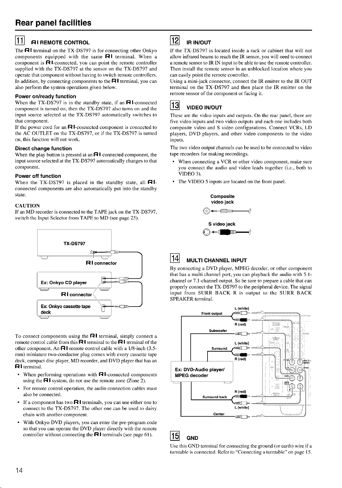
Rear panel facilities
] RIREMOTECONTROL
The R I terminal on the TX-DS797 is for connecting other Onkyo
components equipped with the same RI terminal. When a
component is R I-connected, you call point the remote controller
supplied with the TX=DS797 at the sensor on the TX-DS797 and
operate that component without having to switch remote controllers.
In addition, by connecting components to the R I terminal, you can
also perform the system operations given below.
Power on/ready function
When the TX=DS797 is in the standby state, if an R I-connected
component is tin'ned on, then the TX=DS797 also turns on and the
input source selected at the TX-DS797 automatically switches to
that component.
If the power cord for an R I-connected component is connected to
the AC OUTLET on the TX-DS797, or if the TX-DS797 is turned
on, this function will no1 work.
Direct change function
When the play bulton is pressed at an R I=connected component, the
input source selected at the TX-DS797 automatically changes to that
component.
Power off function
When the TX=DS797 is placed ill the standby state, all RI-
connected components are also automatically put into the standby
state.
] IR IN/OUT
If the TX-DS797 is located inside a rack or cabinet that will not
allow infrared beams to reach the IR sensor, you will need to connect
a remote sensor to IR IN input to be able to use the remote controller.
Then install the remote sensor in an unblocked location where you
can easily point the remote controller.
Using a mini-jack connector, connect the IR emitter to the IR OUT
terminal on the TX=DS797 and then place the IR emitter on the
remote sensor of the component or facing it.
] VIDEO IN/OUT
These are the video inputs and outputs. On the rear panel, there are
five video inputs and two video oulputs and each one includes bolh
composite video and S video configurations. Connect VCRs, LD
players, DVD players, and other video components to the video
inputs.
The two video oulput channels can be used to be connected to video
tape recorders for making recordings.
• When connecting a VCR or other video component, make sure
you connect the audio and video leads together (i.e., both to
VIDEO 3).
• The VIDEO 5 inputs are located on the fl'ont panel.
CAUTION
If an MD recorder is connected to the TAPE jack on the TX-DS797,
switch the Input Selector from TAPE to MD (see page 23).
R I connector
Ex: Onkyo CD player f_-_=_ii]i_.,
R I connector \
Ex: Onkyo cassette tape
deck
Composite
video jack
S video jack
] MULTI CHANNEL INPUT
By connecting a DVD player, MPEG dec_xter, or olher component
that has a multi channel port, you can playback the audio with 5.1=
chamlel or 7.l-channel output. So be sure to prepare a cable that can
properly connect the TX-DS797 to the peripheral device. The signal
input from SURR BACK R is output to the SURR BACK
SPEAKER terminal.
L (white)
To connect components using the R I terminal, simply connect a
remote control cane from this R I terminal to the I--iI terminal of the
olher component. An 17tI remote control cable with a l/8-inch (3.5=
mm) miniature two=conductor plug comes with every cassette tape
deck, compact disc player, MD recorder, and DVD player that has an
R I terminal.
• When performing operations with Rl=connected components
using the I=tI system, do not use the remote zone (Zone 2).
• For remote control operation, the audio connection cables must
also be connected.
• If a component has two R I terminals, you can use either one to
connect to the TX=DS797. The other one can be used to daisy
chain with another component.
• With Onkyo DVD players, you can enter the pre-pmgram code
so that you can operate the DVD player directly with the remote
controller without connecting the R I terminals (see page 61 ).
Centsr
] GND
Use this GND terminal for connecting the ground (or earth) wire if a
turntable is connected. Refer to "Connecting a turntable" on page 15.
14
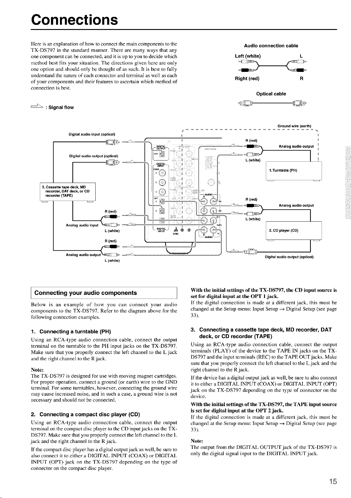
Connections
Here is an explanation of how Goconnect the main components 1o 1he
TX-DS797 in the standard manner. There are many ways that any
one component can be connected, and it is up to you 1o decide which
method best fits your situation. The directions given here are only
one oplion and should only be thought of as such. It is best to fully
understand the nalure of each connector and terminal as well as each
of your components and their features to ascertain which method of
connection is best.
: Signal flow
Audio connection cable
Left (white) L
Right (red) R
Optical cable
Digitalaudioinput(opUcal)
Digital audio output (optical)
1
3. Cassette tape deck, MD
recorder_ DAT deck, or CD
recorder (TAPE)
J R (red)
Analog audio input _
L (white)
R (red)
Analc_
L (white)
Ground wire (earth)
R(red)
Analogaudio output I
I .Turntable (PH)
_ _ clo _ Analog audio output
L (white) I
2.2D player (CD)
k= _J
j __
Digital audio output (optical)
JConnecting your audio components
Below is an example of how you can connect your audio
components to the TX-DS797. Refer to the diagram above for the
following connection examples.
1. Connecting a turntable (PH)
Using an RCA=type audio connection cable, connect the output
terminal on the turntable to the PH input jacks on the TX-DS797.
Make sure that you properly connect the left channel to the L jack
and the right channel to the R jack.
Note:
The TX-DS797 is designed for use with moving magnet cartridges.
For proper operation, connect a ground (or earth) wire to the GND
terminal. For some turntables, however, connecting the ground wire
may cause increased noise, and in such a case, a ground wire is not
necessary and should not be connected.
2. Connecting a compact disc player (CD)
Using an RCA=type audio connection cable, connect the output
terminal on the compact disc player to the CD input jacks on the TX-
DS797. Make sure thai you properly connect the left channel to the L
jack and the right channel to the R jack.
If the compact disc player has a digital oulput jack as well, be sure to
also connect it to either a DIGITAL INPUT (COAX) or DIGITAL
INPUT (OPT) jack on the TX-DS797 depending on the type of
connector on the compact disc player.
With the initial settings of the TX-DS797, the CD input source is
set for digital input at the OPT 1jack.
If the digital connection is made at a different jack, this must be
changed at the Setup menu: Input Setup --_ Digital Setup (see page
33).
3. Connecting a cassette tape deck, MD recorder, DAT
deck, or CD recorder (TAPE)
Using an RCA=type audio connection cable, connect the output
terminals (PLAY) of the device m the TAPE IN jacks on the TX-
DS797 and the input terminals (REC) to the TAPE OUT jacks. Make
sure that you properly connect the left channel to the L jack and the
right channel to the R jack.
If the device has a digital output jack as well, be sure to also connect
it to either a DIGITAL INPUT (COAX) or DIGITAL INPUT (OlYl ")
jack on the TX-DS797 depending on the type of connector on the
device.
With the initial settings of the TX-DS797, the TAPE input source
is set for digital input at the OPT 2 jack.
If the digital connection is made at a different jack, this must be
changed at the Setup menu: Input Setup --_ Digital Setup (see page
33).
Note:
The output from the DIGITAL OUTPUT jack of the TX-DS797 is
only the digital signal input to the DIGITAL INPUT jack.
15
Connections
: Signal flow
Audio connection cable
Left (white)
Right (red)
Digital audioinput (optical)
Video connection cable
S video connection cable
_lllllllll IIIIII __ I
Component video connection cable
PR Pn
Digital audio output (coaxial)
S Video input
Video input
Analog audio R (red)
input
I L (white)
l R (red)
Analog audio "_
output L (white)
Video output
S Video output _--
Y
Y
Component video output
I Connecting your video components
Below is an example of how you can connect your video
components to the TX-DS797. Refer to the diagram above for the
following connection examples.
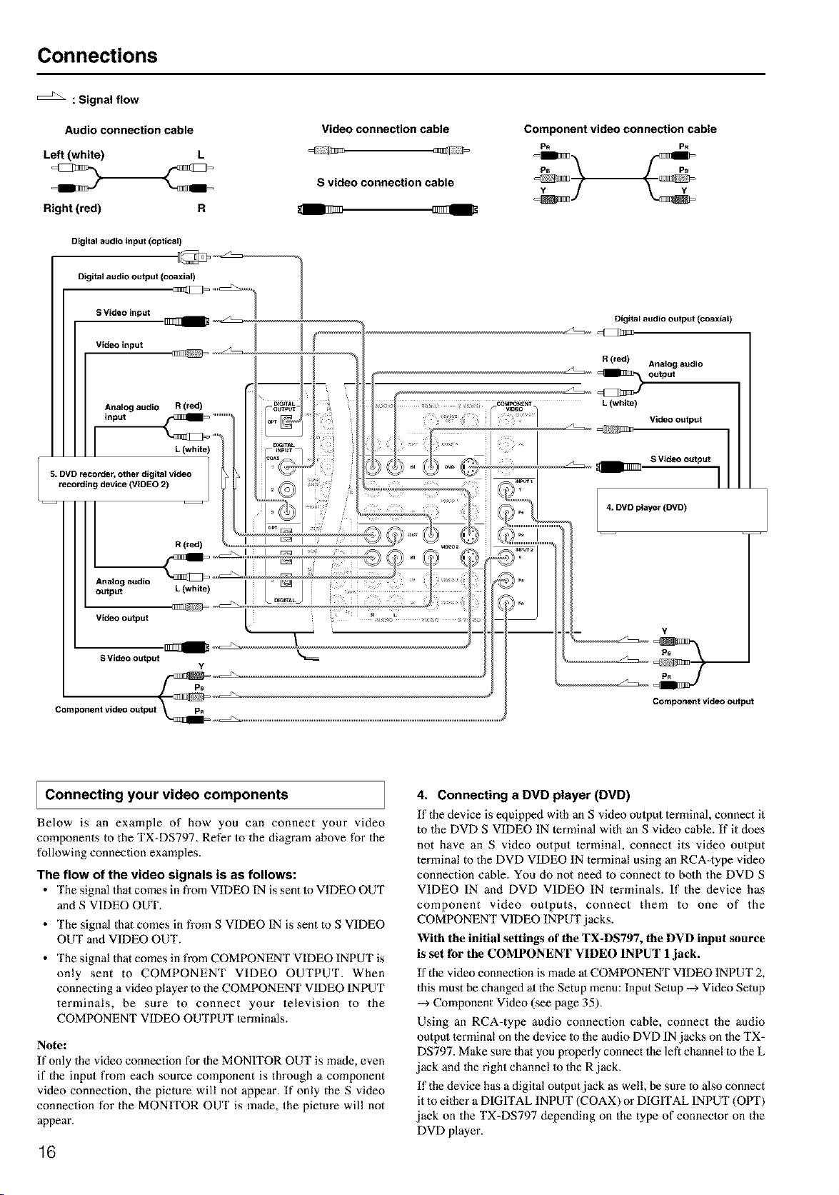
The flow of the video signals is as follows:
• The signal that comes in fi'om VIDEO IN is sent to VIDEO OUT
and S VIDEO OUT.
• The signal that comes in fi'om S VIDEO IN is sent to S VIDEO
OUT and VIDEO OUT.
• The signal that comes in from COMPONENT VIDEO INPUT is
only sent to COMPONENT VIDEO OUTPUT. When
connecting a video player to the COMPONENT VIDEO INPUT
terminals, be sure to connect your television to the
COMPONENT VIDEO OUTPUT lerminals.
Note:
If only the video connection for the MONITOR OUT is made, even
if the input from each source component is through a component
video connection, the picture will not appear. If only the S video
connection for the MONITOR OUT is made, the picture will not
appear.
16
4. Connecting a DVD player (DVD)
If the device is equipped with an S video oulput lerminal, connect it
to the DVD S VIDEO IN terminal with an S video cable. If it does
not have an S video output terminal, connect its video output
terminal to the DVD VIDEO IN terminal using an RCA-type video
connection cable. You do not need to connect to bolh the DVD S
VIDEO IN and DVD VIDEO IN terminals. If the device has
component video outputs, connect them to one of the
COMPONENT VIDEO INPUT jacks.
With the initial settings of the TX-DS797, the DVD input source
is set for the COMPONENT VIDEO INPUT 1jack.
If the video connection is made at COMPONENT VIDEO INPUT 2,
this must be changed ;11the Setup menu: Input Setup -_ Video Setup
-_ Component Video (see page 35).
Using an RCA-type audio connection cable, connect the audio
output terminal on the device Io the audio DVD IN jacks on Ihe TX-
DS797. Make sure that you properly connect the led channel to Ihe L
jack and the right channel to the R jack.
If the device has a digital output jack as well, be sure to also connect
it m either a DIGITAL INPUT (COAX) or DIGITAL INPUT (OPT)
jack on the TX-DS797 depending on the type of connector on the
DVD player.
Connections
S VideO input ._
Video input
Analog audio
input
I
R (red)
6,VCR (VIDEO 1)
Analog audio _
output L (white)
Video output
IIIIIII t
S Video output
R(red) l
Analog audio
L (whde) output
With the initial settings of the TX-DS797, the DVD input source
is set for digital input at the COAX 1 jack.
If the digital connection is made at a different jack, this must be
changed at the Setup menu: Input Setup --_ Digital Setup (see page
33).
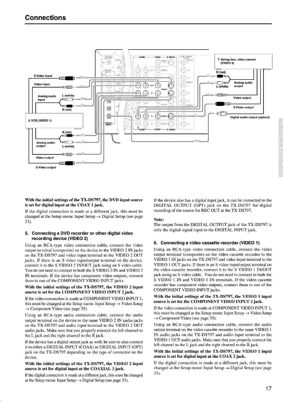
5. Connecting a DVD recorder or other digital video
recording device (VIDEO 2)
Using an RCA-type video connection cable, connect the video
oulput terminal (composite) on the device to the VIDEO 2 IN jacks
on the TX-DS797 and video input terminal to the VIDEO 2 OUT
jacks. If there is an S video input/output terminal on the device,
connect it to the S VIDEO 2 IN!OUT jack using an S video cable.
You do not need to connect to both the S VIDEO 2 IN and VIDEO 2
IN terminals. If the device has component video outputs, connect
them to one of the COMPONENT VIDEO INPUT jacks.
With the initial settings of the TX-DS797, the VIDEO 2 input
source is set for the COMPONENT VIDEO INPUT 2 jack.
If the video connection is made at COMPONENT VIDEO INPUT 1,
this must be changed at the Setup menu: Input Setup --_ Video Setup
--_ Component Video (see page 35).
Using an RCA-type audio connection cable, connect the audio
oulput terminal on the device to the same VIDEO 2 IN audio jacks
on the TX-DS797 and audio input terminal to the VIDEO 2 OUT
audio jacks. Make sure that you properly connect the left channel to
the L jack and the right channel 1o the R jack.
If the device has a digital oulput jack as well, be sure to also connect
it to either a DIGITAL INPUT (COAX) or DIGITAL INPUT (OPT)
jack on the TX-DS797 depending on the type of connector on the
device.
With the initial settings of the TX-DS797, the VIDEO 2 input
source is set for digital input at the COAXIAL 3 jack.
If the digital connection is made ata different jack, this must be changed
at the Setup menu: InputSetup --_ Digital Setup (see page 33).
If the device also has a digital input jack, it can be connected to the
DIGITAL OUTPUT (OPT) jack on the TX-DS797 for digital
recording of the source for REC OUT at the TX-DS797.
Note:
The output from the DIGITAL OUTPUT jack of the TX=DS797 is
only the digital signal input to the DIGITAL INPUT jack.
6. Connecting a video cassette recorder (VIDEO 1)
Using an RCA=type video connection cable, connect the video
output terminal (composite) on the video cassette recorder to the
VIDEO 1 IN jacks on the TX-DS797 and video input terminal m the
VIDEO 1 OUT jacks. If there is an S video inpul/output terminal on
the video cassette recorder, connect it to the S VIDEO 1 IN/OUT
jack using an S video cable. You do not need to connect m both 1be
S VIDEO 1 IN and VIDEO 1 IN terminals. If the video casselte
recorder has component video oulputs, connect them to one of the
COMPONENT VIDEO INPUT jacks.
With tile initial settings of the TX-DS797, the VIDEO 1 input
source is set for the COMPONENT VIDEO INPUT 2 jack.
If the video connection is made at COMPONENT VIDEO INPUT 1,
this must be changed at the Setup menu: Input Setup --_ Video Setup
--_ Component Video (see page 35).
Using an RCA=type audio connection cable, connect the audio
oulput lerminal on the video cassette recorder to the same VIDEO 1
IN audio jacks on the TX=DS797 and audio input terminal to the
VIDEO 1 OUT audio jacks. Make sure that you properly connect the
left channel to the L jack and the right channel to the R jack.
With tile initial settings of the TX-DS797, the VIDEO 1 input
source is set for digital input at the COAX 2 jack.
If the digital connection is made at a different jack, this must be
changed at the Setup menu: Input Setup --_ Digital Setup (see page
33).
17
Connections
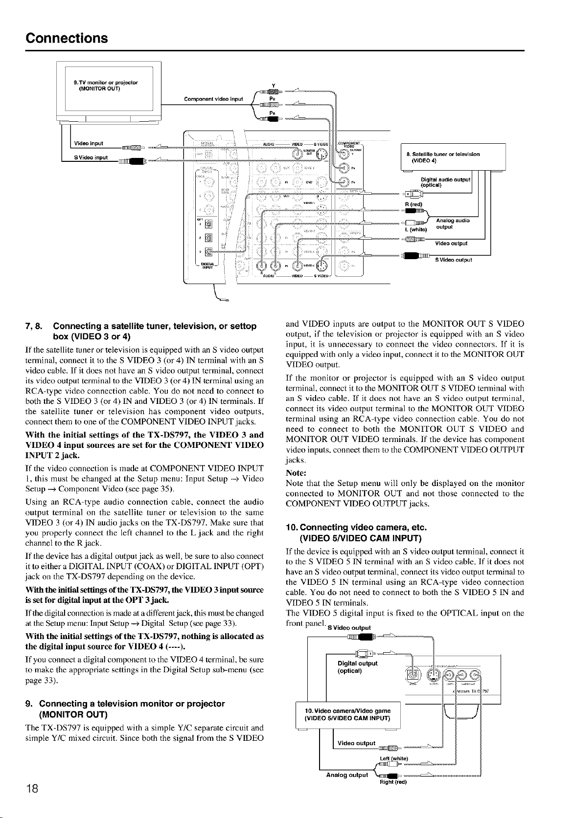
9.TV monEtor or projector
(MONITOR OUT)
Video input
S Video input
Y
Component video input
7, 8. Connecting a satellite tuner, television, or settop
box (VIDEO 3 or 4)
If the satellite (uner or lelevision is equipped with an S video oulput
terminal, connect it to the S VIDEO 3 (or 4) IN terminal with an S
video cable_ If it does not have an S video oulput terminal, connect
its video oulput terminal Io the VIDEO 3 (or 4) IN terminal using an
RCA=type video connection cable. You do not need 1o connect to
both the S VIDEO 3 (or 4) IN and VIDEO 3 (or 4) IN terminals. If
the satellite tuner or television has component video outputs,
connect them 1oone of the COMPONENT VIDEO INPUT jacks.
With the initial settings of the TX-DS797, the VIDEO 3 and
VIDEO 4 input sources are set for the COMPONENT VIDEO
INPUT 2 jack.
If the video connection is made at COMPONENT VIDEO INPUT
1, this must be changed at the Setup menu: Input Setup --_ Video
Setup --> Component Video (see page 35).
Using an RCA-type audio connection cable, connect the audio
output terminal on the satellite tuner or television to the same
VIDEO 3 (or 4) IN audio jacks on the TX-DS797. Make sure that
you properly connect the left channel to the L jack and the right
channel to the R jack.
If the device has a digital output jack as well, be sure to also connect
it to either a DIGITAL INPUT (COAX) or DIGrI'AL INPUT (OPT)
jack on the TX=DS797 depending on the device.
With the initial settings of the TX-DS797, the VIDEO 3 input source
is set for digital input at the OPT 3 jack.
If the digital connection is made at a different jack, Ibis must be changed
at the Setup menu: Input Setup --_ Digital Setup (see page 33).
With the initial settings of the TX-DS797, nothing is allocated as
the digital input source for VIDEO 4 (----).
If you connect a digital component to the VIDEO 4 terminal, be sure
to make the appropriate settings in the Digital Setup sub-menu (see
page 33).
9. Connecting a television monitor or projector
(MONITOR OUT)
The TX=DS797 is equipped with a simple Y/C separate circuit and
simple Y/C mixed circuit. Since both the signal from the S VIDEO
18
and VIDEO inputs m'e output to the MONITOR OUT S VIDEO
output, if the television or projector is equipped with an S video
input, it is unnecessary to connect the video connectors. If it is
equipped with only a video input, connect it to 1he MONITOR OUT
VIDEO output.
If the monitor or projector is equipped with an S video output
terminal, connect it 1o the MONITOR OUT S VIDEO terminal with
an S video cable. If it does not have an S video output terminal,
connect its video output terminal to the MONITOR OUT VIDEO
terminal using an RCA=type video connection cable. You do not
need to connect to both the MONITOR OUT S VIDEO and
MONfI'OR OUT VIDEO terminals. If the device has component
video inputs, connect 1hem to the COMPONENT VIDEO OUTPUT
jacks.
Note:
Note that the Setup menu will only be displayed on the monitor
connected to MONITOR OUT and not those connected to the
COMPONENT VIDEO OUTPUT jacks.
10. Connecting video camera, etc.
(VIDEO 5/VIDEO CAM INPUT)
If the device is equipped with an S video output terminal, connect it
to the S VIDEO 5 IN terminal with an S video cable. If it does not
have an S video output terminal, connect its video output terminal to
the VIDEO 5 IN terminal using an RCA=type video connection
cable. You do not need to connect to both the S VIDEO 5 IN and
VIDEO 5 IN terminals.
The VIDEO 5 digital input is fixed to the OPTICAL input on the
front panel, sVideooutput
.....;L,2'2,
l [ Video output ._
Analog output _IIIIIIIB=_ ....................................
Right (red)
Connecting speakers
Before connecting the speaker:s, place them correctly by consulting
the instruction manuals thai came with them.
For surround playback, the configuration and placement of your
speake_:s are very important.
For THX surround EX playback, we recommend that you use a
THX speaker syslem that is certified by Lucasfilm Ltd.
I Ideal speaker configuration
• Front right and left speakers
• Centerspeaker
Produces a rich sound image by serving as a sound source for
the front right and left speakers and enhancing the sonic
movement.
• Surround right and left speakers
Adds three-dimensional sonic movement and produces
environmental sound associated with the background and effect
sound for each scene.
• Surround back speaker
Required for enjoying THX Surround EX, DTS-ES Matrix 6.1,
or DTS-ES Discrete 6.1 audio. For audio using surround back
right and surround back left speakers, a separately-sold 2-
channel power amplifier is required.
Lucasfihn/THX recommends the use of two Surround Back
speakei:s to enjoy the full potential of THX Surround EX. An
external stereo power amplifier will need 1o be used to power
the two speakers from the Pre-Amp out lerminals.
However, if you are unable to position two speakers in your
listening environment, a single surround speaker can be used
and the TX-DS797 has an internal amplifier to power this
speaker for your convenience.
• Subwoofer
Produces powerful and heavy bass.
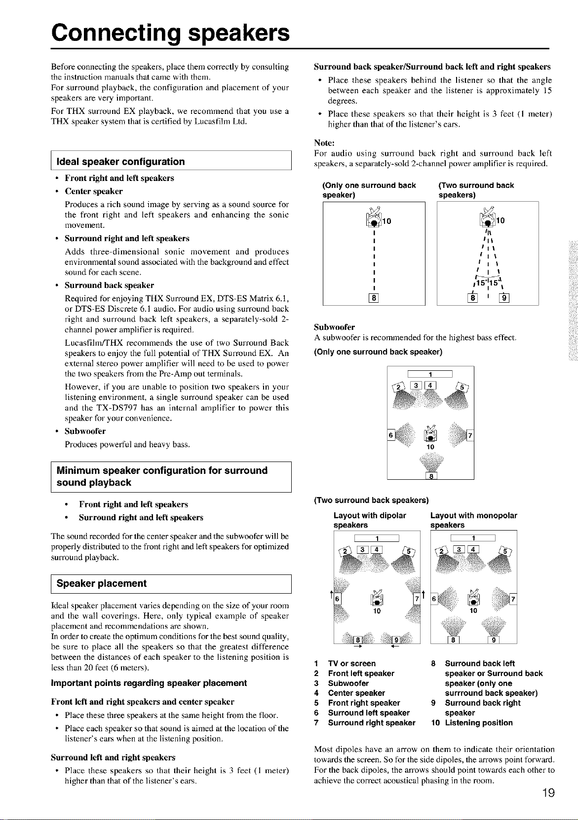
Minimum speaker configuration for surround
sound playback
Surround back speaker/Surround back left and right speakers
• Place these speakers behind the listener so that the angle
between each speaker and the listener is approximately 15
degrees.
• Place these speakers so that their height is 3 feet (1 meier)
higher than that of the listener's ears.
Note:
For audio using surround back right and surround back left
speaker, a separately-sold 2-channel power amplifieris required.
(Only one surround back
speaker)
[]
(Two surround back
speakers)
Front right and left speakers
Surround right and left speakers
The sound recorded for the center speaker and the subwoofer will be
properly dislributed to the front right and left speakers for optimized
surround playback.
I Speaker placement
Ideal speaker placement varies depending on the size of your room
and the wall coverings. Here, only typical example of speaker
placement and recommendations are shown.
In order Io create the optimum conditions for the best sound qualily,
be sure to place all the speakers so that the greatest difference
between the distances of each speaker to the listening position is
less than 20 feet (6 meters).
Important points regarding speaker placement
Front left and right speakers and center speaker
• Place these three speakers at the same height from the floor.
• Place each speaker so that sound is aimed at the location of the
listener's ears when at the listening position.
Surround left and right speakers
• Place these speakers so that their height is 3 feet (1 meter)
higher than that of the listener's ears.
lit
IHI
IHI
I H i
i H 1
i I i
_a
115°uu15I
®,®
1 TV or screen 8 Surround back left
2 Front left speaker speaker or Surround back
3 Subwoofer speaker (only one
4 Center speaker surrround back speaker)
5 Front right speaker 9 Surround back right
6 Surround left speaker speaker
7 Surround right speaker 10 Listening position
Most dipoles have an arrow on them to indicale their orientation
towards the screen. So for the side dipoles, 1he arrows point forward.
For the back dipoles, the an'ows should point towards each other to
achieve the correct acoustical phasing in the room.
19
(Two surround back speakers)
Layout with dipolar Layout with monopolar
speakers speakers
[ 1 ] [ 1 I
10
6
E 1 3
Subwoofer
A subwoofer is recommended for the highest bass effect.
(Only one surround back speaker)
Connecting speakers
Connecting speakers
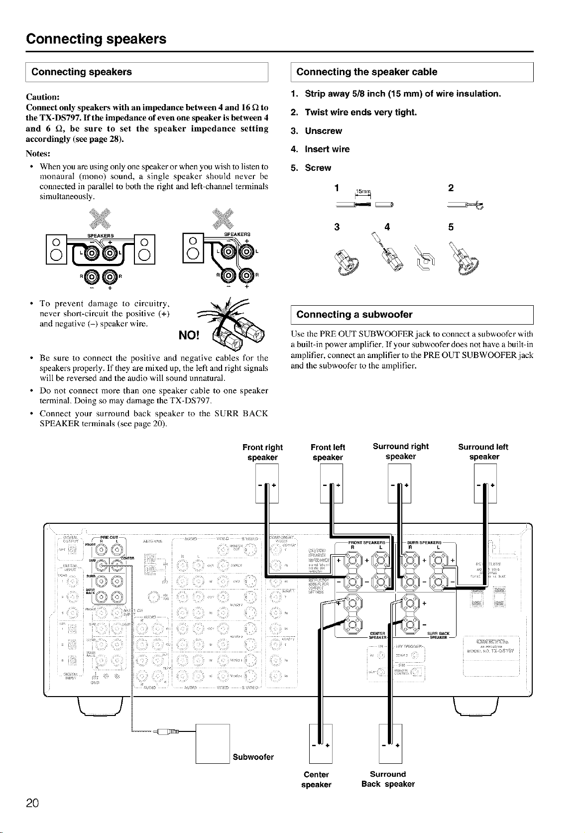
Caution:
Connect only speakers with an impedance between 4 and 16 _ to
the TX-DS797. If the impedance of even one speaker is between 4
and 6 £_, be sure to set the speaker impedance setting
accordingly (see page 28).
Notes:
• When you are using only one speaker or when you wish to listen to
monaural (mono) sound, a single speaker should never be
connected in parallel to both the right and left-channel terminals
simultaneously.
Connecting the speaker cable
1. Strip away 518 inch (15 mm) of wire insulation.
2. Twist wire ends very tight.
3. Unscrew
4. Insert wire
5. Screw
1 _ 2
°@@.
+ +
• To prevent damage to circuitry,
never short-circuit the positive (+)
and negative (-) speaker wire.
• Be sure to connect the positive and negative cables for the
speakers properly. If they are mixed up, the left and right signals
will be reversed and the audio will sound unnatural.
• Do not connect more than one speaker cable to one speaker
terminal. Doing so may damage the TX-DS797.
• Connect your surround back speaker to the SURR BACK
SPEAKER lerminals (see page 20).
3 4 5
Connecting a subwoofer
Use the PRE OUT SUBWOOFER jack Io connect a subwoofer with
a built-in power amplifier. If your subwoofer does not have a built-in
amplifier, connect an amplifier to 1hePRE OUT SUBWOOFER jack
and the subwoofer to the amplifier.
Front right Front left Surround right Surround left
speaker speaker speaker speaker
2O
Center
speaker
Surround
Back speaker
Connecting the remote zone (Zone 2)
speakers
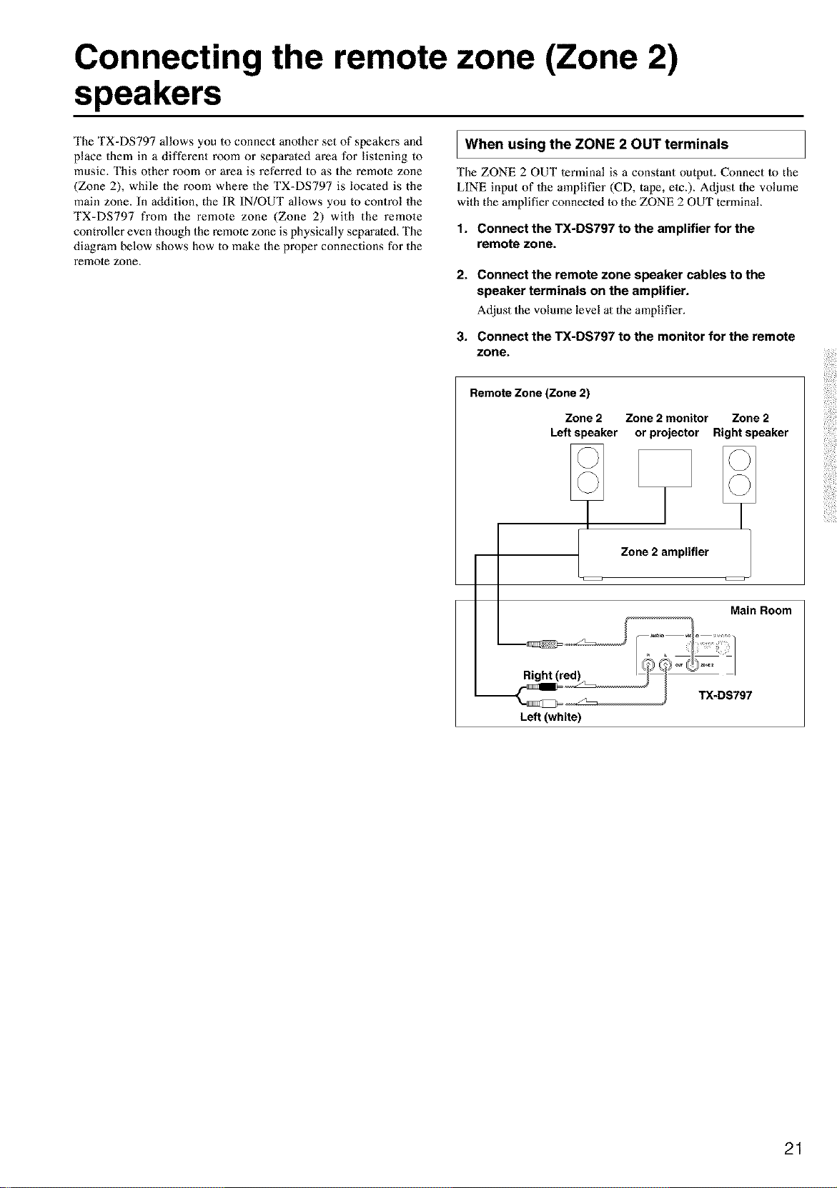
The TX=DS797 allows you to connect anolher set of speaker,s and
place them in a different room or separated area for listening to
music. This other room or area is referred to as the remole zone
(Zone 2), while the room where the TX=DS797 is located is the
main zone. In addition, the IR IN!OUT allows you to control the
TX=DS797 from the remote zone (Zone 2) with the remote
controller even though the remote zone is physically separated. The
diagram below shows how to make the proper connections for the
remole zone.
I When using the ZONE 2 OUT terminals
The ZONE 2 OUT terminal is a constant output. Connect to the
LINE input of the amplifier (CD, tape, etc.). Adjust the volume
with the amplifier connected to the ZONE 2 OUT terminal.
t. Connect the TX-DS797 to the amplifier for the
remote zone.
2. Connect the remote zone speaker cables to the
speaker terminals on the amplifier.
Adjust the volume level at the amplifier.
3. Connect the TX-DS797 to the monitor for the remote
zone.
Remote Zone (Zone 2)
Zone 2 Zone 2 monitor Zone 2
Left speaker or projector Right speaker
Zone 2 amplifier
Main Room
Left (white)
21
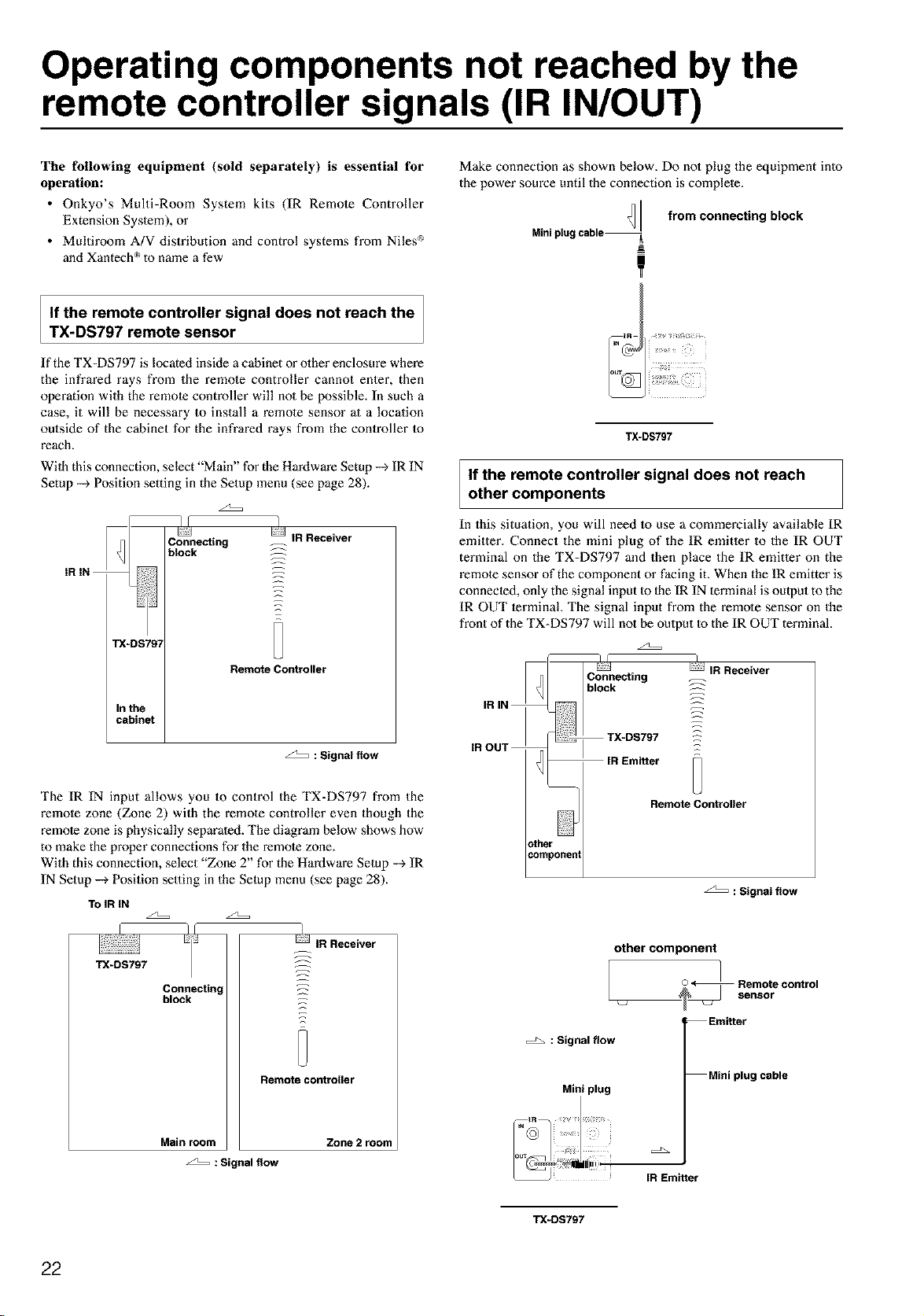
Operating components not reached by the
remote controller signals (IR IN/OUT)
The following equipment (sold separately) is essential for
operation:
• Onkyo's Multi-Room System kits (IR Remote Controller
Extension Syslem), or
• Multiroom A/V distribution and control systems from Niles _
and Xantech _'_to name a few
Make connection as shown below. Do not plug the equipment into
the power source until the connection is complete.
Minipiug
from connecting block
!
If the remote controller signal does not reach the
TX-DS797 remote sensor
If the TX=DS797 is located inside a cabinet or olher enclosure where
the infrared rays from the remo_e controller cannot enter, then
operation with the remote controller will no1 be possible. In such a
case, it will be necessary to install a remo_e sensor at a location
outside of the cabinet for the infrared rays from the controller Io
reach.
Wilh this connection, select "Main" for the Hardware Setup --_ IR IN
Setup --_ Position setting in the Setup menu (see page 28).
z2::::=
i i
TX-DS797
If the remote controller signal does not reach
other components
In this situation, you will need to use a commercially available IR
emitter. Connect the mini plug of the IR emitter to the IR OUT
terminal on the TX=DS797 and then place the IR emitter on the
remote sensor of the component or facing it. When the IR emitter is
connected, only the signal input Io Ihe IR IN terminal is output to the
IR OUT terminal The signal input from the remole sensor on the
front of the TX-DS797 will not be oulput to the IR OUT terminal.
z2=:=
: Signal flow
The IR IN input allows you to control the TX=DS797 from the
remole zone (Zone 2) with the remote controller even though the
remote zone is physically separated. The diagram below shows how
to make the proper connections for the remote zone.
With this connection, select "Zone 2" for the Hardware Setup --_ IR
IN Setup --_ Position setting in the Setup menu (see page 28).
TOIR IN
_/f ]
IR Receiver
TX-DS797 _
Connectin, _z
block _:
Remote controller
Main room Zone 2 room
: Signal flow
: Signal flow
Miniplug
: Signal flow
other component
/ oontro.
Emitter
Miniplug cable
[R Emitter
TX-DS797
22
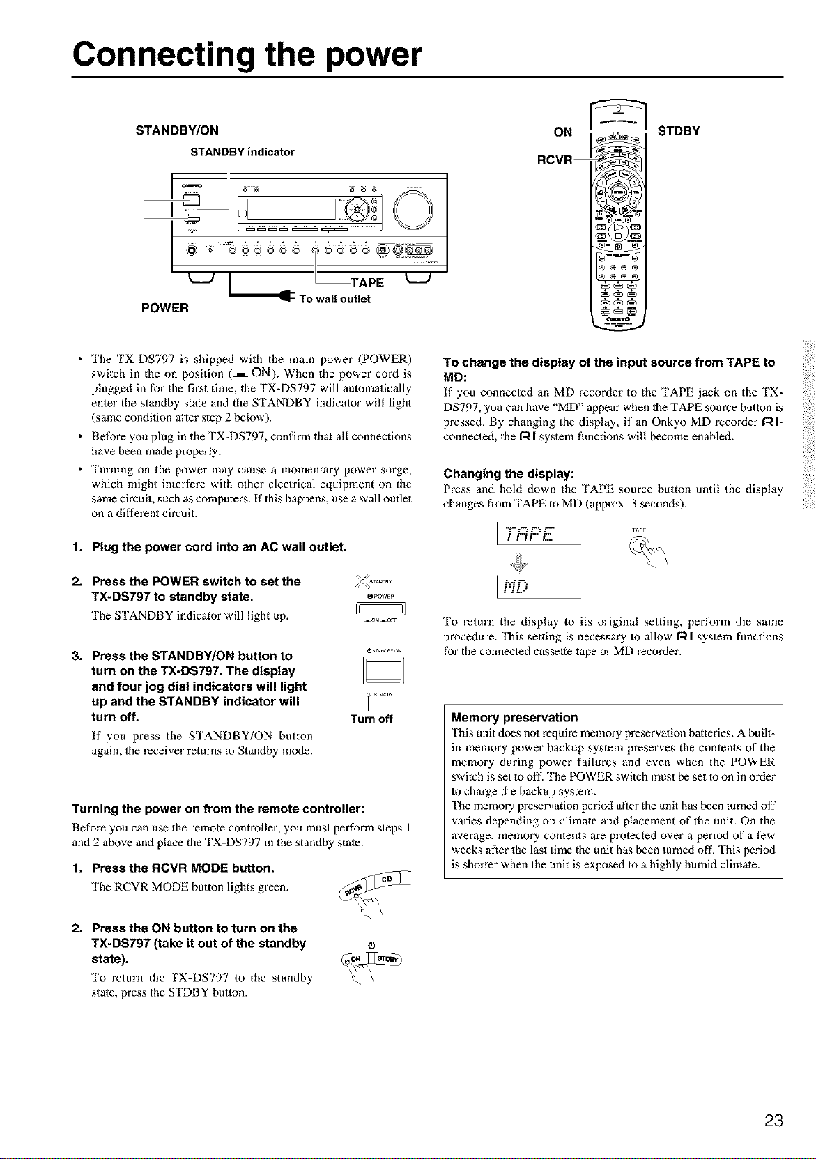
Connecting the power
STANDBY/ON
STANDBY indicator
I
/ To u"e,"E
POWER
ITDBY
• The TX-DS797 is shipped with the main power (POWER)
switch in the on position (.L ON). When the power cord is
plugged in for the fii_st time, the TX-DS797 will automatically
enter the standby state and the STANDBY indicator will light
(same condition after step 2 below).
• Before you plug in the TX-DS797, confirm that all connections
have been made properly.
• Turning on the power may cause a momentary power surge,
which might interfere with other electrical equipment on the
same circuit, such as computers. If 1hishappens, use a wall outlet
on a different circuit.
1. Plug the power cord into an AC wall outlet.
2. Press the POWER switch to set the
TX-DS797 to standby state, e.....
The STANDBY indicator will light up. =.....
3. Press the STANDBY/ON button to
turn on the TX-DS797. The display
and four jog dial indicators will light
up and the STANDBY indicator will
turn off.
If you press the STANDBY/ON button
again, 1he receiver returns to Standby mode.
Turn off
Turning the power on from the remote controller:
Before you can use the remote controller, you must perform steps 1
and 2 above and place the TX-DS797 in the standby state.
1. Press the RCVR MODE button.
The RCVR MODE button lights green.
To change the display of the input source from TAPE to
MD:
If you connected an MD recorder to the TAPE jack on the TX-
DS797, you can have "MD" appear when 1he TAPE source button is
pressed. By changing the display, if an Onkyo MD recorder/:_ I-
connected, the/:_ I syslem functions will become enabled.
Changing the display:
Press anti hold down the TAPE source button until the display
changes from TAPE to MD (approx. 3 seconds).
I ......
." L.$ L.."L.
ilit i.,,
I'.iD
To return the display to its original setting, perform the same
procedure. This selling is necessary Io allow I'_ I system functions
for the connected casselte tape or MD recorder.
Memory preservation
This unit does no1 require memory preservation batteries. A built-
in memory power backup system preserves the conlents of the
memory during power failures and even when the POWER
switch is set 1ooff. The POWER switch must be set to on in order
to charge the backup system.
The memory preservation period after the unit has been turned off
varies depending on climale and placement of the unit. On the
average, memory conlents are protected over a period of a few
weeks after the last time the unit has been turned off. This period
is shorter when the unit is exposed to a highly humid climate.
2. Press the ON button to turn on the
TX-DS797 (take it out of the standby
state).
To return the TX-DS797 to the standby
state, press the STDBY button.
(B
23
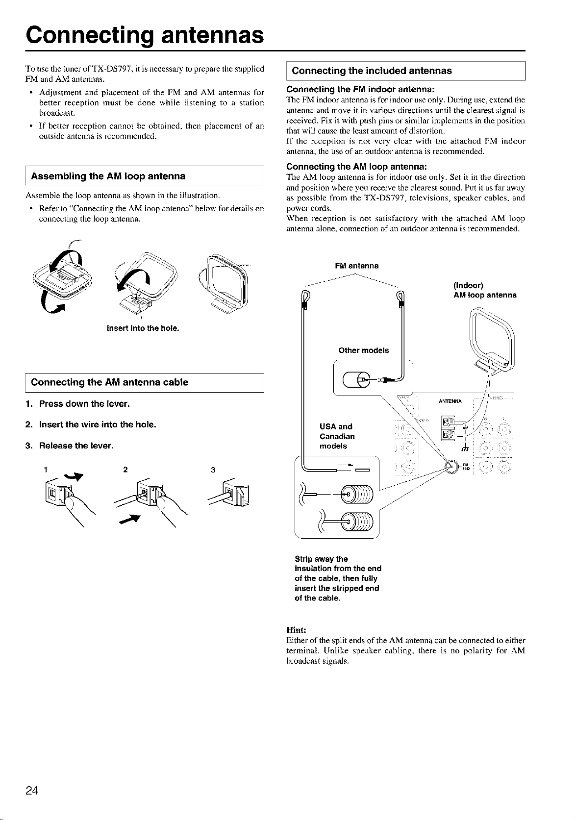
Connecting antennas
To use lhe tuner of TX-DS797, it is necessary to prepare the supplied
FM and AM antennas.
• Adjustment and placement of the FM and AM antennas for
better reception must be done while listening to a station
broadcast.
• If better reception cannot be obtained, then placement of an
outside antenna is recommended.
I Assembling the AM loop antenna
Assemble the loop antenna as shown in the illustration.
• Refer to "Connecting the AM loop antenna" below for details on
connecting the loop antenna.
Connecting the included antennas
Connecting the FM indoor antenna:
The FM indoor antenna is for indoor use only. During use, extend the
antenna and move it in various directions until the clearest signal is
received. Fix it with push pins or similar implements in the position
thai will cause the least amount of distortion.
If the reception is not very clear with the attached FM indoor
antenna, lhe use of an ouldoor antenna is recommended.
Connecting the AM loop antenna:
The AM loop anlenna is for indoor use only. Set it in the direction
and position where you receive the clearest sound. Put it as far away
as possible from the TX-DS797, televisions, speaker cables, and
power cords.
When reception is not satisfactory with the attached AM loop
antenna alone, connection of an ouldoor antenna is recommended.
@
Insert into the hole.
I Connecting the AM antenna cable
1. Pressdown the lever.
2. Insert the wire into the hole.
3. Release the lever.
1 2 3
FM antenna
Other models
(Indoor)
AM loop antenna
Strip away the
insulation from the end
of the cable, then fully
insert the stripped end
of the cable.
Hint:
Either of the split ends of the AM antenna can be connecled to either
terminal. Unlike speaker cabling, there is no polarity for AM
broadcast signals.
24
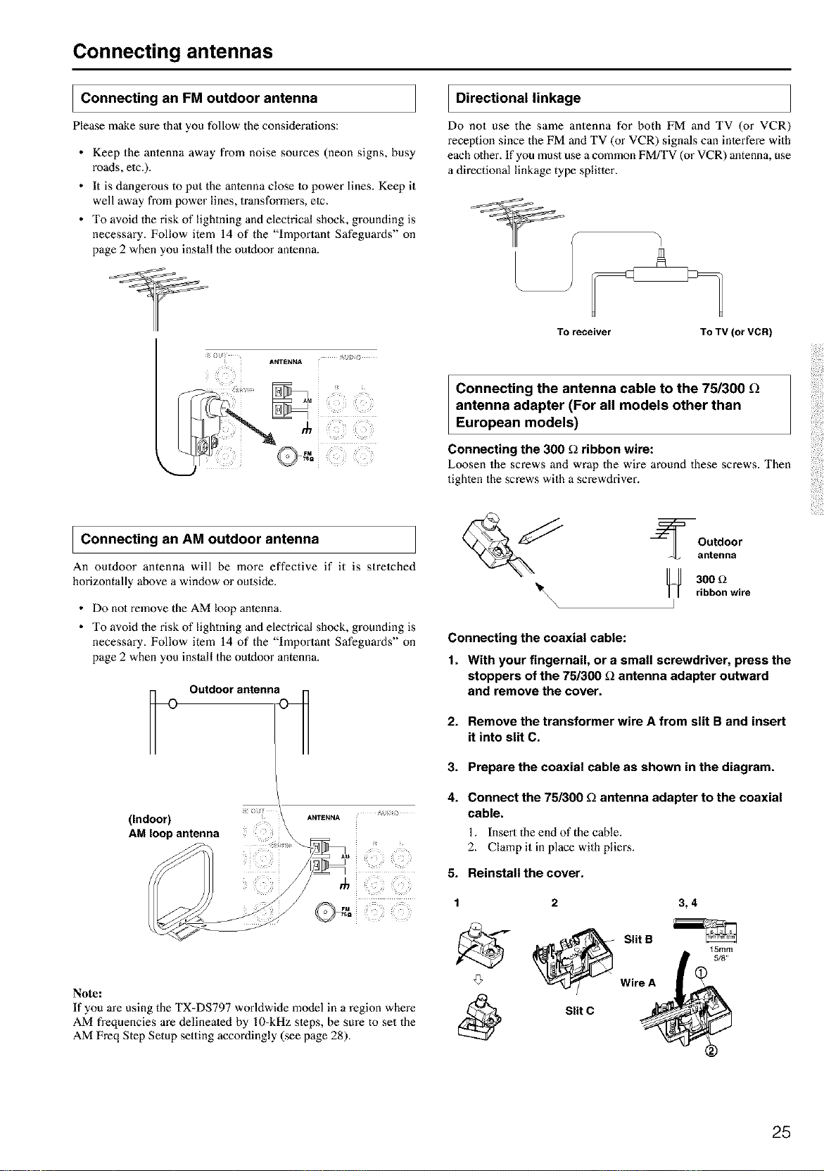
Connecting antennas
I Connecting FM outdoor antenna
an
Please make sure that you follow the considerations:
• Keep the antenna away from noise sources (neon signs, busy
roads, etc.).
• It is dangerous to put the antenna close Io power lines. Keep it
well away from power lines, transformm_s, elc.
• To avoid the risk of lightning and electrical shock, grounding is
necessary. Follow item 14 of the "Important Safeguards" on
page 2 when you install the outdoor antenna.
I Directional linkage
Do not use the same antenna for both FM and TV (or VCR)
reception since the FM and TV (or VCR) signals can interfere with
each other. If you must use a common FMfI'V (or VCR) antenna, use
a directional linkage type splitler.
I
TO receiver TO TV (or VCR)
Connecting the antenna cable to the 75/300
antenna adapter (For all models other than
European models)
Connecting the 300 _ ribbon wire:
Loosen the screws and wrap the wire around these screws. Then
tighten the screws with a screwdriver.
I Connecting AM outdoor antenna
an
An outdoor antenna will be more effective if it is stretched
horizontally above a window or outside.
• Do no1remove the AM loop anlenna.
• To avoid the risk of lightning and electrical shock, grounding is
necessary. Follow item 14 of the "Important Safeguards" on
page 2 when you install the outdoor antenna.
Outdoor antenna_
(Indoor)
AM loop antenna
ANTENNA
Note:
If you are using the TX-DS797 worldwide model in a region where
AM frequencies are delinealed by 10-kHz sleps, be sure to set the
AM Freq Step Setup setting accordingly (see page 28).
_ Outdoor
antenna
_ 300 _2
_1_\\\ ] ribbon wire
Connecting the coaxial cable:
1. With your fingernail, or a small screwdriver, press the
stoppers of the 75/300 _ antenna adapter outward
and remove the cover.
2. Remove the transformer wire A from slit B and insert
it into slit C.
3. Prepare the coaxial cable as shown in the diagram.
4.
Connect the 75/300 fl antenna adapter to the coaxial
cable.
1. Insert the end of the cable.
2. Clamp it in place with pilings.
5. Reinstall the cover.
1 2 3, 4
'_- @ Slit S _Smm
5/8"
Wire A
Slit C
25
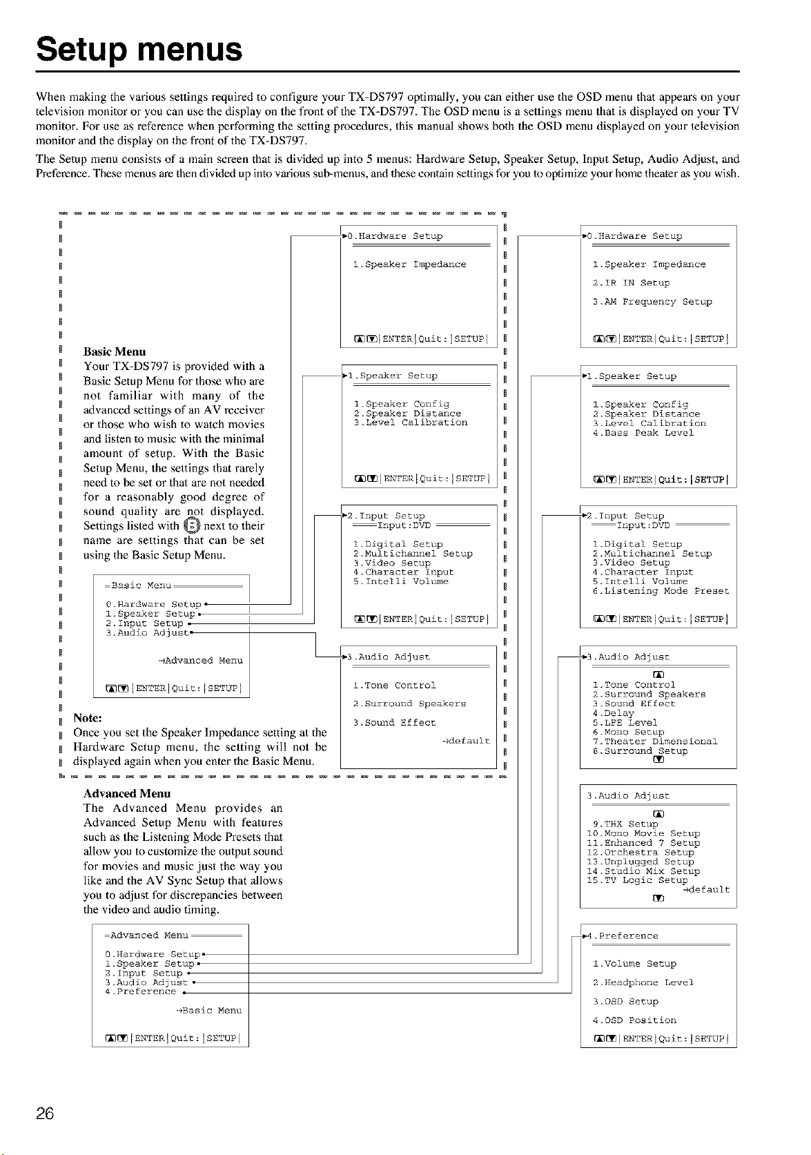
Setup menus
When making the various settings required to configure you" TX-DS797 optimally, you can either use the OSD menu thai appears on your
television monilor or you can use the display on the front of the TX-DS797. The OSD menu is a settings menu that is displayed on your TV
monitor. For use as reference when performing the selting procedures, this manual shows both the OSD menu displayed on your lelevision
monilor and the display on the front of the TX-DS797.
The Setup menu consists of a main screen that is divided up into 5 menus: Hardware Setup, Speaker Setup, Input Setup, Audio Adjust, and
Preference. These menus are then divided up into various sub-menus, and these contain settings for you to optimize your home theater as you wish.
Basic Menu
Your TX-DS797 is provided with a
Basic Setup Menu for those who are
not familiar with many of the
advanced settings of an AV receiver
or those who wish to watch movies
and listen Io music with the minimal
amount of setup. With the Basic
Setup Menu, the settings that rarely
need to be set or that are not needed
for a reasonably good degree of
sound quality are not displayed.
Settings listed with Q next to their
name are settings that can be set
using the Basic Setup Menu.
Basic Menu
0.Hardware Setup, I
l. Speaker Setup. I
2.1nput Setup •
3.Audio Adjust.
_Advanced Menu
_[_]ENTERIQuit:[SETUP j
Note:
Once you set the Speaker Impedance setting at the
Hardware Setup menu, the setting will not be
displayed again when you enter the Basic Menu.
_0.Hardware Setup
l.Speaker Impedance
[_[_[ENTERJQuit:ISETUP l
_l.Speaker Setup
l.Speaker Config
2.Speaker Distance
3.Level Calibration
_[_IENTER[Quit:JSETUPI
_2.1nput Setup
Input:DVD
l.Digital Setup
2.Nultichannel Setup
3.Video Setup
4.Character Input
S.Intelli Volume
®®[ENTERJQuit:ISETUP I
_3.Audio Adjust
l.Tone Control
2.Surround Speakers
3.Sound Effect
-+default
Advanced Menu
The Advanced Menu provides an
Advanced Setup Menu with features
such as the Listening Mode Presets that
allow you to customize the output sound
for movies and music just the way you
like and the AV Sync Setup that allows
you to adjust for discrepancies between
the video and audio timing.
Advanced Menu
0.Hardware Setup.
l.Speaker Setup.
2.1nput Setup .
3.Audio Adjust •
4.Preference •
-gBasic Menu
[_[_[ENTERJQuit:ISETUP ]
.O.Hardware Setup
l.Speaker Impedance
2.IR IN Setup
3._ Frequency Setup
[]_IENTERIQuit:ISETUPJ
-l.Speaker Setup
l.Speaker Config
2.Speaker Distance
3.Level Calibration
4.Bass Peak Level
_]ENTNRIQuit:[SETUP [
_2.1nput Setup
Input:DVD
l.Digital Setup
2.Multichannel Setup
3.Video Setup
4.Character Input
5.1ntelli Volume
6.Listening Mode Preset
[_IENTERIQuit:JSETUPI
_3.Audio Adjust
l.Tone Control
2.Surround Speakers
3.Sound Effect
4.Delay
5.LFE Level
6.Mono Setup
7.Theater Dimensional
8.Surround Setup
3.Audio Adjust
9.THX Setup
10.Mono Movie Setup
ll. Enhanced 7 Setup
12.Orchestra Setup
13.Unplugged Setup
14.Studio Mix Setup
15.TV Logic Setup
edefault
_D
.Preference
l.Volume Setup
2.Headphone Level
3.OSD Setup
4.OSD Position
[_[_IENTERIQuit:JSETUPI
26
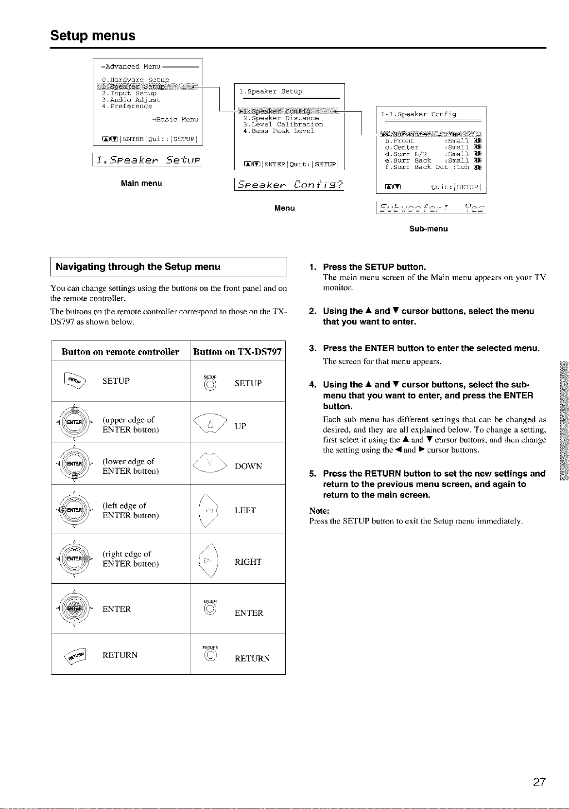
Setup menus
=Advanced Menu
O,Hardware Setup
2_Input Setup
3.Audio Adjust
4.Preference
_Basic Menu
_[_IENTER[Quit:[SETUPI
Ii..KPe. kerS'e*t,P
Main menu
l.Speaker Setup
2.Speaker Distance
3.Level Calibration
4.Bass Peak Level
_[_[ENTERIQuit:ISETUP I
[SF-ea ker- Con{i_ ?
Menu
l-l.Speaker Config
b.Front :Small
c.Center :Small
d.Surr L/R :Small
e.Surr Back :Small
f.Surr Back Out :ich
_ Quit:ISETUP 1
Sub-menu
I Navigating through the Setup menu
You can change settings using the buttons on the front panel anti on
the remote controller.
The buttons on the remote controller correspond to those on the TX-
DS797 as shown below.
Button on remote controller Button on TX-DS797
_) SETUP SETUP
(upper edge of
ENTER button) UP
(lower edge of DOWN
ENTER button)
(lefl edge of LEFT
ENTER button)
(right edge of
ENTER button) RIGHT
ENTER ENTER
@_ RETURN RETURN
1. Press the SETUP button.
The main menu screen of the Main menu appears on your TV
monitor.
2. Using the • and • cursor buttons, select the menu
that you want to enter.
3. Press the ENTER button to enter the selected menu.
The screen for that menu appears.
4.
Using the • and • cursor buttons, select the sub-
menu that you want to enter, and press the ENTER
button.
Each sub-menu has different settings that can be changed as
desired, and they are all explained below. To change a selling,
first select it using 1he • and • cursor buttons, and then change
the setting using 1he • and • cunsor buttons.
5. Press the RETURN button to set the new settings and
return to the previous menu screen, and again to
return to the main screen.
Note:
Press the SETUP button to exit the Setup menu immediately.
27
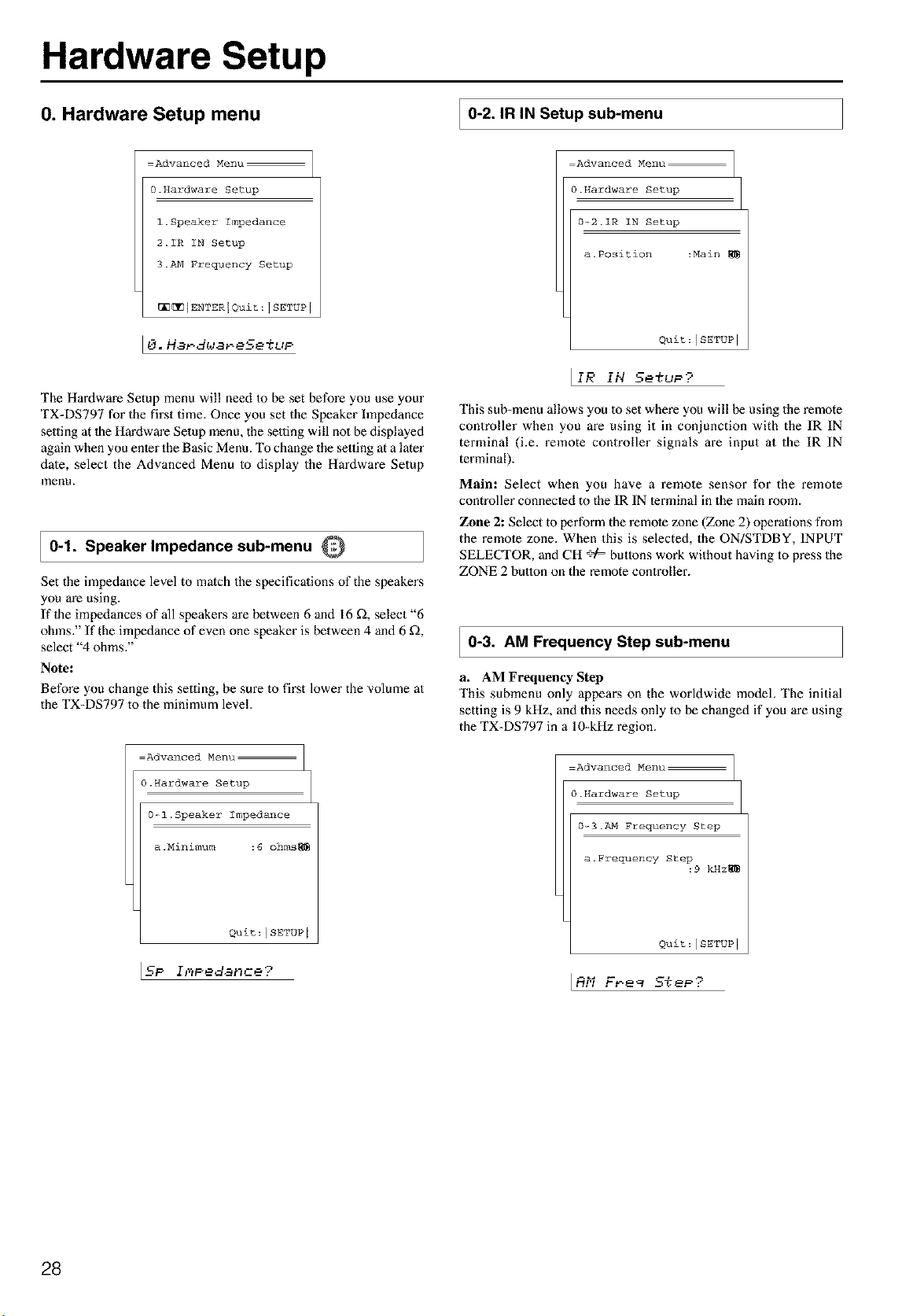
Hardware Setup
0. Hardware Setup menu
0-2. IR IN Setup sub-menu
:Advanced Menu
0.Hardware Setup
l.Speaker Impedance
2.IR IN Setup
3.AM Frequen0y Setup
_[_[ENTERIQuit:ISETUPI
The Hardwm'e Setup menu will need m be set before you use your
TX-DS797 for the first time. Once you set the Speaker hnpedance
setting at lhe Hardwm'e Setup menu, the setting will no1 be displayed
again when you enter the Basic Menu. To change the setting at a later
date, select the Advanced Menu to display the Hardware Setup
menu.
0-1. Speaker Impedance sub-menu Q
Set the impedance level to match the specificalions of the speakers
you are using.
If 1he impedances of all speakers are between 6 and 16 _, select "6
ohms." If the impedance of even one speaker is between 4 and 6 _,
select "4 ohms."
Note:
Before you change this setting, be sure to first lower the volume at
the TX-DS797 to the minimum level.
=Advanced Menu
0.Hardware Setup
0-_1 .Speaker Impedance
a .Minimum :6 ohms_
Quit : ISETUP [
IN ............
:Advanced Menu
0.Hardware Setup
0-_2.1R IN Setup
a. P0siti0n :Main
Quit:ISETUP I
_IR IN 5etuP?
This sub-menu allows you 1o set where you will be using the remote
controller when you are using it in conjunction with the IR IN
terminal (i.e. remote controller signals are input at the IR IN
terminal).
Mail*: Select when you have a remote sensor for the remote
controller connected to the IR IN terminal in the main room.
Zone 2: Select to perform the remote zone (Zone 2) operations from
the remote zone. When this is selected, the ON/STDBY, INPUT
SELECTOR, and CH ÷/= buttons work without having to press the
ZONE 2 button on the remote controller.
0-3. AM Frequency Step sub-menu
a. AM Frequency Step
This submenu only appem_s on the worldwide model. The initial
setting is 9 kHz, and this needs only to be changed if you are using
the TX-DS797 in a 10-kHz region.
Advanced Menu
0.Hardware Setup
0--3._ Frequency Step
a.Frequency Step
:9 kHz_
Quit:ISETUP I
IRhi F_ee _TeP;"
28

Speaker Setup
1. Speaker Setup menu
After you have installed the TX-DS797, connected all the
components, and determined the speaker layout, it is now time to
perform the settings in the Speaker Setup menu for the optimmn
sound acoustics for your environment and speaker layout.
Before you perform the following settings, it is important that you
first determine the following characteristics:
• The types and sizes of the speakers 1hat are connecled.
• The distance from each speaker to your normal listening
position.
(Only one surround back
speaker)
=Advanced Menu
l.Speaker Setup
l.Speaker Config
2.Speaker Distance
3.Level Calibration
4.Bass Peak Level
_[_IENTERIQuit:ISETUPI
Li. 5Peaked. 5e%t,P
Memo:
(Only one surround back
speaker)
Monitor I
I1-1. Speaker Config sub-menu Q
Here you will enter which speakers are connected anti the size of
each speaker.
=Advanced Menu
l.Speaker Setup
l--l.Speaker Config
a. Subwoofer :Yes
b. Front :Small
c. Center :Small
d. Surr L/R :Small
e. Surr Back :Small
f.Surr Back Out :Ich
_[_ Quit:[SETUP I
[_[ lmm
(Two surround back speakers)
=Basic Menu
l.Speaker Setup
l.Speaker Config
2.Speaker Distance
3.Level Calibration
_[_IENTERIQuit:ISETUPI
11-SPeaker" 5e%t,P
(Two surround back speakers)
Tip:
When setting the speaker size in the Speaker Config sub-menu, use
the guidelines given below.
Large: The complete frequency range for the channel you are
setting will be oulput from the speaker.
Smalh Frequencies of the channel you are setting lower than 80
Hz will be output from the subwoofer. If there is no subwoofer,
then the oulput will be from 1he left and right front speakers. (Set
all speakers for THX speaker systems to "small?')
a. Subwoofer
Yes: Select when a subwoofer is connecled.
No: Select when a subwoofer is not connected.
b. Front
Large: Select if the front speakers are large sized.
Small: Select if the front speakers are small sized.
• If"No" is selected for the Subwoofer setting, 1hen this setting
is fixed to "Large."
c. Center
None: Select if no center speaker is connected.
Large: Select if the center speaker is large sized.
Small: Select if the cenler speaker is small sized.
• If "Small" is selected for the Front setting, then "Large"
cannot be selecled for this setting.
d. Surround L/R
None: Select if no surround left and right speakers are
connected.
Large: Select if lhe sun_und left and right speakers are lane sized.
Snmlh Select if lhe sun_und left and right speakers are small sized.
• If "Small" is selected for the Front setting, then "Large"
cannot be selecled for this setting.
e. Surround Bk
None: Select if no surround back left and right speakers are connected.
Large: Selecl if the surround back left and righl speakers are large sized.
Small: Select if the surround back lefl and right speakers are
small sized.
• If"None" is selected for the Surround L/R setting, the display
disappears from the screen.
• If "Small" is selected for the Surround L/R setting, then
"Large" cannot be selected for this setting.
f. Surf Back Out
lch: Select if Ihere is only one surround back speaker.
2oh (PREOUT only): Select if there are two surround back
speakers. (For preout output only.)
29
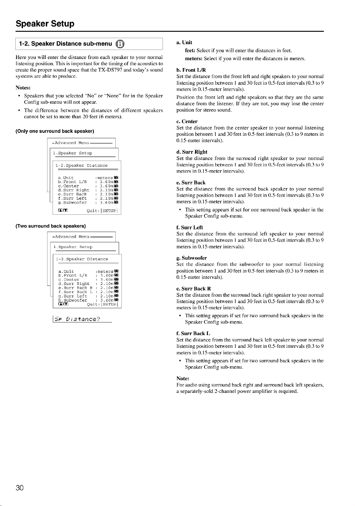
Speaker Setup
1-2. Speaker Distance sub-menu Q
Here you will enter the distance from each speaker to your normal
listening position. This is important for the timing of the acoustics to
create the proper sound space that the TX=DS797 and today's sound
systems are able to produce.
Notes:
• Speakers that you selected "No" or "None" for in the Speaker
Config sub=menu will no1 appem'.
• The difference between the distances of different speakers
cannot be set to more than 20 feet (6 meters).
(Only one surround back speaker)
Advanced Menu:
l.Speaker Setup
l-_2.Speaker Distance
a Unit :meters_
b. Front L/R 3.60m_
c. Center 3.60m_
d. Surr Right 2.10m_
e. Surr Back 2.10m_
f.Surr Left 2.10m_
g. Subwoofer 3.60m_
_[_ Quit:ISETUP l
(Two surround back speakers)
Advanced Menu
I Speaker Setup
12Speaker Distance
a Unit :meters_
b. Front L/R 3.60m_
c.Center 3.60m_
d. Surr Right 2.10m_
e. Surr Back R 2.10m_
f.Surr Back L 2.10m_
g. Surr Left 2.10m_
h. Subwoofer 3.60m_
_[_ Quit:JSETUP 1
[S_ r_:.- " ...... -7
a. Unit
feet: Select if you will enter the distances in feet.
meters: Select if you will enter the distances in meters.
b. Front L/R
Set the distance from the front left and right speakers to your normal
listening position between l and 30 feet in 0.5=feet intervals (0.3 to 9
meters in 0.15=meter intervals).
Position the front left and right speakers so that they are the same
distance from the listener. If they m'e not, you may lose the center
position for stereo sound.
c. Center
Set the distance from the center speaker to your normal listening
position between l and 30 feet in 0.5-feet intervals (0.3 Io 9 meters in
O.15-meter intervals).
d. Surf Right
Set the distance from the surround right speaker to your normal
listening position between 1 and 30 feet in 0.5-feet intervals (0.3 to 9
meters in 0.15-meter intervals).
e. Surr Back
Set the distance from the surround back speaker to your normal
listening position between l and 30 feet in 0.5-feet intervals (0.3 to 9
meters in 0.15-meter intervals).
• This setting appears if set for one surround back speaker in the
Speaker Config sub-menu.
t Surr Left
Set the distance from the surround left speaker to your normal
listening position between 1 and 30 feet in 0.5-feet intervals (0.3 to 9
meters in 0.15-meter intervals).
g. Subwoofer
Set the distance from the subwoofer to your normal listening
position between 1 and 30 feet in 0.5-feet intervals (0.3 Io 9 meters in
0.15-meter intervals).
e. Surf Back R
Set the distance from the surround back right speaker to your normal
listening position between l and 30 feet in 0.5-feet intervals (0.3 to 9
meters in 0.15=meter intervals).
• This setting appears if set for two surround back speakers in the
Speaker Config sub-menu.
t Sorr Back L
Set the distance from the surround back left speaker to your normal
listening position between l and 30 feet in 0.5-feet intervals (0.3 to 9
meters in 0.15=meter intervals).
• This setting appears if set for two surround back speakers in the
Speaker Config sub-menu.
Note:
For audio using surround back right and surround back left speakers,
a separately-sold 2-channel power amplifier is required.
3O
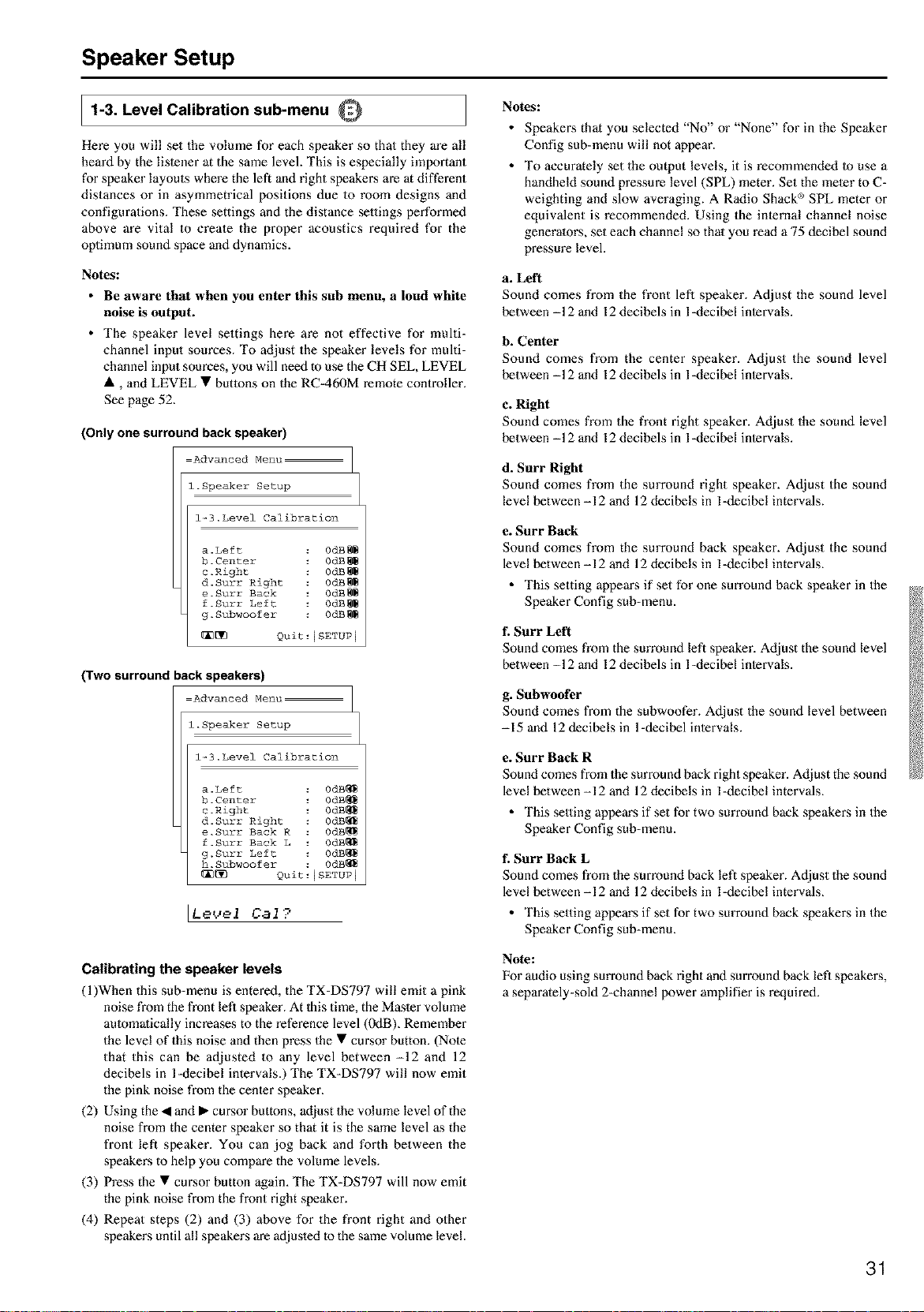
Speaker Setup
Jl-3. Level Calibration sub-menu Q
Here you will set the volume for each speaker so that they are all
heard by the lislener at the same level. This is especially important
for speaker layouts where the left and right speakers are at different
distances or in asymmetrical positions due to room designs and
configurations. These settings and the distance selfings performed
above are vital to create the proper acoustics required for the
oplimum sound space and dynamics.
Notes:
• Be aware that when you enter this sub menu, a loud white
noise is output.
• The speaker level settings here are not effective for multi-
channel input sources. To adjust the speaker levels for multi-
channel input sources, you will need to use the CH SEL, LEVEL
•, and LEVEL • buttons on the RC-460M remote controller.
See page 52.
(Only one surround back speaker)
Advanced Menu
i Speaker Setup
13Level Calibration
a Left 0dB_
b.Center 0dB_
c.Right 0dB_
d. Surr Right 0dB_
e.Surr Back 0dB_
f.Surr Left 0dB_
g Subwoofer 0dB_
[_ Quit:ISETUP I
(Two surround back speakers)
Advanced Menu
i Speaker Setup
13Level Calibration
a Left 0dB_
b.Center 0dB_
c.Right 0dB_
d.Surr Right 0dB_
e.Surr Back R 0dB_
f.Surr Back L 0dB_
g.Surr Left 0dB_
h.Subwoofer 0dB_
_ Quit:ISETUP I
[Le{_el Cat?
Calibrating the speaker levels
(l)When this sub-menu is entered, the TX-DS797 will emit a pink
noise from the front left speaker. At Ihis time, the Masler volume
aummalically increases to the reference level (0dB)_ Remember
the level of this noise and then press the • cursor button. (Note
that this can be adjusted to any level between -12 and 12
decibels in l-decibel intervals.) The TX-DS797 will now emit
the pink noise from the center speaken
(2) Using the • and • cursor buttons, adjust the volume level of the
noise from the center speaker so that it is the same level as the
front left speaker. You can jog back and forth between the
speakers to help you compare the volume levels.
(3) Press the • cursor button again. The TX-DS797 will now emit
the pink noise from the front right speaker.
(4) Repeat steps (2) and (3) above for the front right and other
speakers until all speakers are adjusled to the same volume level.
Notes:
• Speakers that you selected "No" or "None" for in the Speaker
Config sub-menu will not appear.
• To accurately set the output levels, it is recommended to use a
handheld sound pressure level (SPL) meter. Set the meier to C-
weighting and slow averaging. A Radio Shack _)SPL meter or
equivalent is recommended. Using the internal channel noise
generators, set each channel so that you read a 75 decibel sound
pressure level.
a. Left
Sound comes from the front left speaker. Adjust the sound level
between -12 and 12 decibels in l-decibel intervals.
b. Center
Sound comes from the center speaker. Adjust the sound level
between -12 and 12 decibels in l-decibel intervals.
c. Right
Sound comes from the front right speaker. Adjust the sound level
between -12 and 12 decibels in l-decibel intervals.
d. Surr Right
Sound comes from the surround right speaker. Adjust the sound
level between -12 and 12 decibels in l-decibel intervals.
e. Surf Back
Sound comes from the surround back speaker. Adjust the sound
level between -12 and 12 decibels in l-decibel intervals.
• This setting appears if set for one surround back speaker in the
Speaker Config sub-menu.
f. Surf Left
Sound comes from the surround left speaker. Adjust the sound level
between -12 and 12 decibels in l-decibel intervals.
g. Subwoofer
Sound comes from the subwoofer. Adjust the sound level between
-15 and 12 decibels in 1-decibel intervals.
e. Surr Back R
Sound comes from the surround back right speaker. Adjust the sound
level between -12 and 12 decibels in l-decibel intervals.
• This setting appears if set for two surround back speakers in the
Speaker Config sub-menu.
f. Surf Back L
Sound comes from the surround back left speaker. Adjust the sound
level between -12 and 12 decibels in l-decibel intervals.
• This setting appears if set for two surround back speakers in the
Speaker Config sub-menu.
Note:
For audio using surround back right and surround back left speakers,
a separately-sold 2-channel power amplifier is required.
31
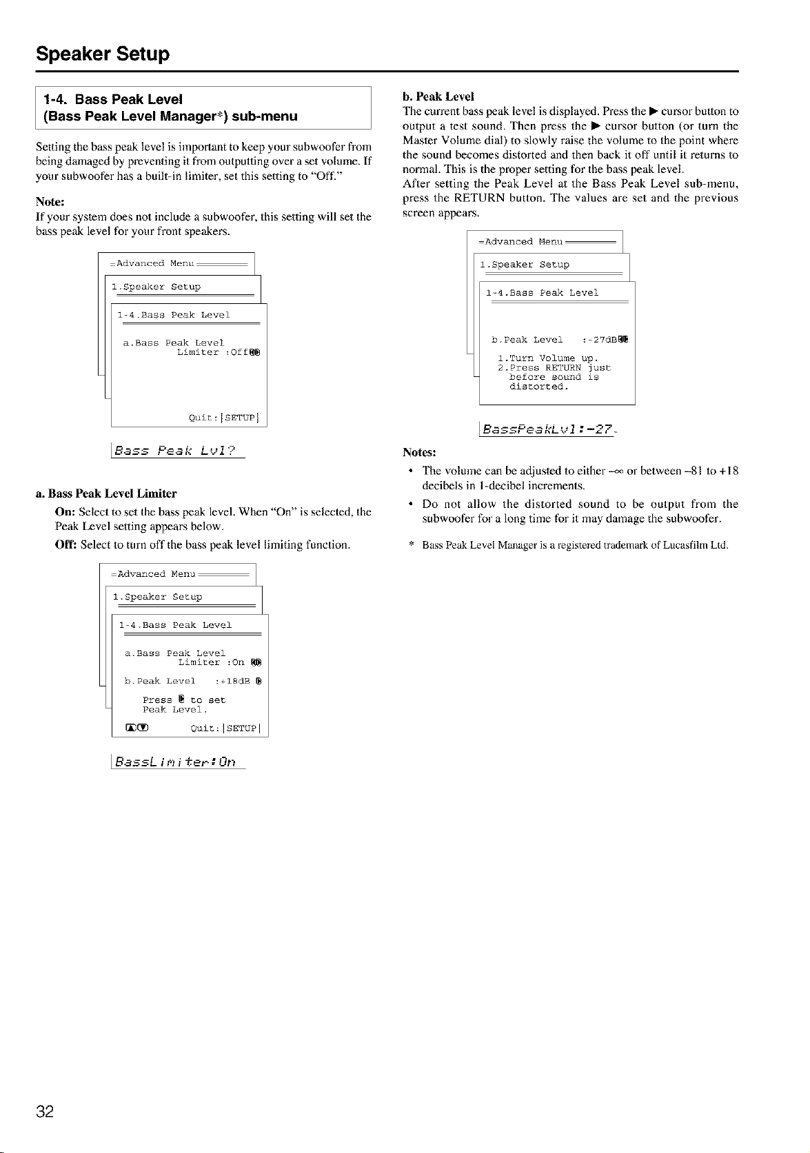
Speaker Setup
1-4. Bass Peak Level
(Bass Peak Level Manager*) sub-menu
Setting the bass peak level is important to keep your subwoofer from
being damaged by preventing it from outpmfing over a set volume. If
your subwoofer has a built-in limiter, set this setting to "Oft'."
Note:
If your system does no1 include a subwoofer, this setting will set the
bass peak level for your front speakers.
Advanced Menu
l.Speaker Setup
l-4.Bass Peak Level
a.Bass Peak Level
Limiter :Off_
Quit:ISETUP I
a. Bass Peak Level Limiter
On: Select to set the bass peak level. When "On" is selected, the
Peak Level setting appears below.
Off: Select Io turn offthe bass peak level limiting function.
Advanced Menu
l.Speaker Setup
l--4.BassPeak Level
a.Bass Peak Level
Limiter :On
b.Peak Level :+lSdB
Press _ to set
Peak Level.
_[]_ Quit:ISETUP i
lSassLii
b. Peak Level
The current bass peak level is displayed. Press the • cursor button to
output a test sound. Then press the • era'sot button (or turn the
Masler Volume dial) to slowly raise the volume to the point where
the sound becomes distorted and then back it off until it returns Io
normal. This is the proper setting for the bass peak level
After setting the Peak Level at the Bass Peak Level sub-menu,
press the RETURN button. The values are set and the previous
screen appears.
Advanced Menu
l.Speaker Setup
l-4.Bass Peak Level
b. Peak Level :--27dB_
l.Turn Volume up.
2.Press RETURN just
before sound is
distorted.
l
[E' ............. :
1
Notes:
• The volume can be adjusled lo either _ or between -81 Io+18
decibels in l-decibel increments.
• Do not allow the distorted sound to be output from the
subwoofer for a long time for it may damage the subwoofer.
* Bass Peak Level Manager is a registered trademark of Lucasfilm Lid
32
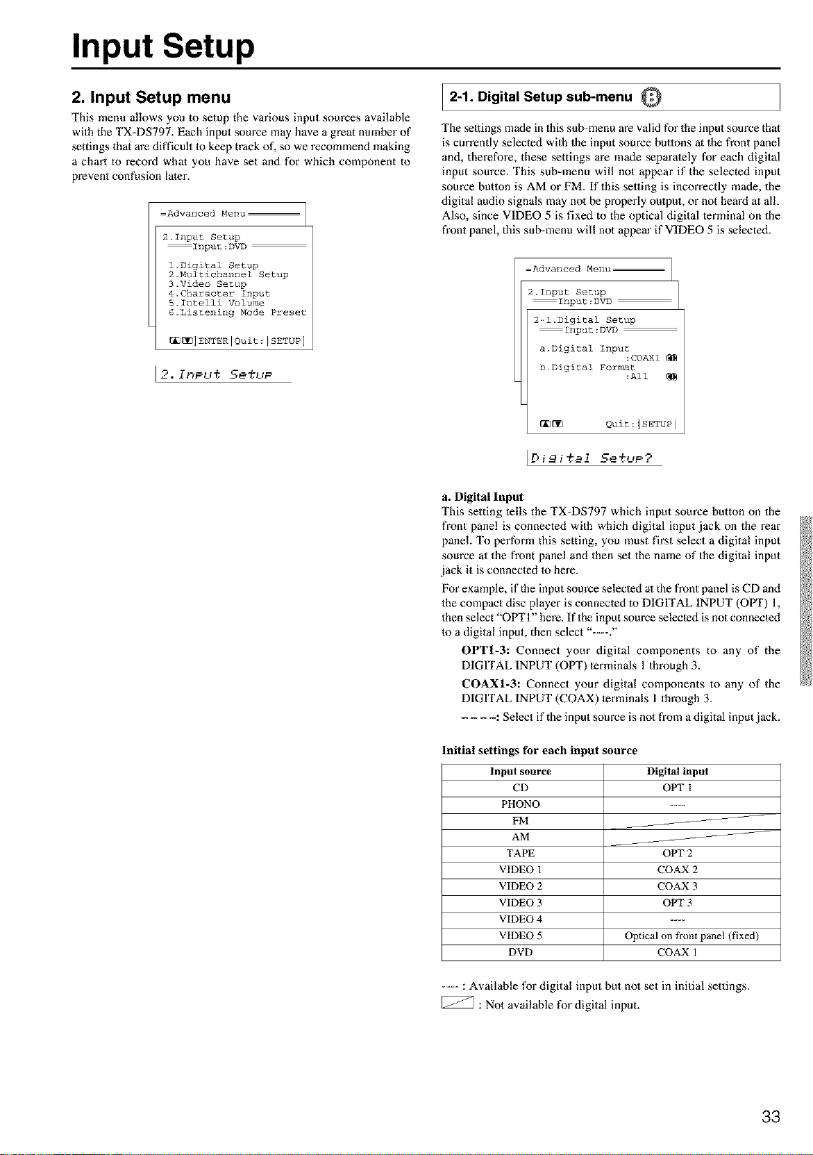
Input Setup
2. Input Setup menu
This menu allows you to setup the various input sources available
with the TX-DS797. Each input source may have a great nmnber of
settings that are difficult 1o keep track of, so we recommend making
a chart to record what you have set and for which component to
prevent confusion later.
Advanced Menu
2.Input Setup
Input:DVD
3.Video Setup
4.Character Input
5.Intelli Volume
6.Listening Mode Preset
_1 ENTER IQuit : I SETUPI
2-1. Digital Setup sub-menu O
The seltings made in this sub-menu are valid for the input source that
is currently selected with the input source buttons at the front panel
and, therefore, these settings are made separately for each digital
input source, This sub-menu will not appear if the selected input
source betlon is AM or FM. If this selling is incorrectly made, the
digital audio signals may no1 be properly omput, or not heard at all
Also, since VIDEO 5 is fixed to the optical digital terminal on the
front panel, this sub-menu will not appear if VIDEO 5 is selected.
Advanced Menu
2.1nput Setup
Input:DVD
2--l.Digital Setup
Input:DVD
a. Digital Input
:COAXI
b. Digital Format
:All
_[_ Quit :1SETUP I
[Dimi%aiSe%uP?
a. Digital Input
This setting tells the TX-DS797 which input source button on the
front panel is connected with which digital input jack on the rear
panel To perform this setting, you must first select a digital input
source at the front panel and then set the name of the digital input
jack it is connecled 1o here.
For example, if the input source selecled al the front panel is CD and
the compact disc player is connecled to DIGITAL INPUT (OfVl") 1,
then select "OPT 1" here. If the input source selected is not connected
Io a digital input, then select "--."
OPT1-3: Connect your digital components to any of the
DIGITAL INPUT (OPT) terminals 1 through 3.
COAX1-3: Connect your digital components to any of the
DIGITAL INPUT (COAX) terminals I through 3.
.... : Select if the input source is not from a digital input jack.
Initial settings for each input source
Input source
CD
PHONO
FM
AM
TAPE
VIDEO 1
VIDEO 2
VIDEO 3
VIDEO 4
VIDEO 5
DVD
Digital input
OPT I
OPT2
COAX 2
COAX3
OPT 3
Optical on _ont panel (fixed)
COAX1
....: Available for digital input but no1 set in initial settings.
[_ : Not available for digital input.
33
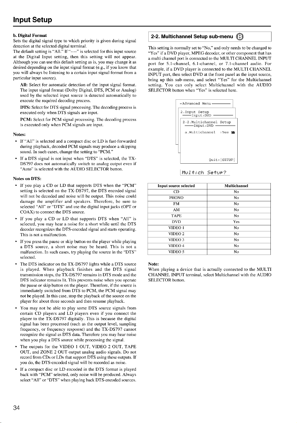
Input Setup
b. Digital Format
Sets the digital signal type Io which priority is given during signal
deleetion at the selected digital terminal
The default setting is "AIL" If "---" is selected for this input source
at the Digital Input setting, then this setting will not appear.
Although you can use this default setting as is, you may change it as
desired depending on the input signal formal (e.g., if you know thai
you will always be lislening Io a certain input signal formal from a
particular input source)_
All: Select for automatic delection of the input signal format
The input signal format (Dolby Digital, DTS, PCM or Analog)
used by the selecled input source is detected automatically to
execme the required decoding process.
DTS: Select for DTS signal processing. The decoding process is
exeemed only when DTS signals are input.
PCM: Select for PCM signal processing. The decoding process
is executed only when PCM signals are input.
Notes:
• If "All" is selected and a compact disc or LD is fast-forwarded
during playback, decoded PCM signals may produce a skipping
sound. In such cases, change the se,ing 1o "PCM."
• If a DTS signal is not input when "DTS" is selecled, the TX-
DS797 does not automalically switch to analog output even if
"Amo" is selecled with the AUDIO SELECTOR button.
Notes on DTS:
• If you play a CD or LD that supports DTS when the "PCM"
se,ing is selected on the TX-DS797, the DTS encoded signal
will not be decoded and noise will be output. This noise could
damage the amplifier and speakers. Therefore, be sure to
selected "All" or "DTS" and use the digital input jacks (OPT or
COAX) 40 connect the DTS source.
• If you play a CD or LD that supports DTS when "All" is
selected, you may hear a noise for a short while until the DTS
decoder recognizes the DTS-encoded signal and starts operating.
This is no1 a malfunction.
• If you press the pause or skip button on the player while playing
a DTS source, a short noise may be heard. This is not a
malfunction. In such cases, try playing the source in the "DTS"
selected.
• The DTS indicator on the TX-DS797 lights while a DTS source
is played. When playback finishes and the DTS signal
transmission slops, the TX-DS797 remains in DTS mode and the
DTS indicator remains lit. This prevents noise when you operate
the pause or skip button on the player. Therefore, if the source is
immediately swilcbed from DTS 1o PCM, the PCM signal may
not be played. In this case, stop 1be playback of the source on the
player for about three seconds and then resmne playback.
• You may not be able to play some DTS source signals from
certain CD players and LD playm:s even if you connect the
player to the TX-DS797 digitally. This is because the digital
signal has been processed (such as the output level, sampling
frequency, or frequency response) and the TX-DS797 cannot
recognize the signal as DTS data. Therefore you may hear noise
when you play a DTS source while processing the signal
• The outputs for the VIDEO I OUT, VIDEO 2 OUT, TAPE
OUT, and ZONE 2 OUT output analog audio signals. Do not
record from CDs or LDs thai support DTS using these outputs. If
you do, 1heDTS-encoded signal will be recorded as noise.
• If a compact disc or LD encoded in the DTS format is played
back with "PCM" selected, only noise will be produced. Always
select "All" or "DTS" when playing back DTS-encoded sources.
2-2. Multichannel Setup sub-menu Q
This se,ing is normally set to "No," and only needs 1o be changed to
"Yes" if a DVD player, MPEG decoder, or other component 1hal has
a multi channel port is connected to 1he MULTI CHANNEL INPUT
port for 5.1-channek 6.l-channel, or 7.l-channel audio. For
example, if a DVD player is connecled 40 the MULTI CHANNEL
INPUT port, then select DVD at the front panel as the input source,
bring up this sub-menu, and select "Yes" for the Multichannel
setting. You can only select Multichannel with the AUDIO
SELECTOR button when "Yes" is selecled here.
Advanced Menu
2.1nput Setup
Input:DVD
2-2.Multichannel Setup
Input:DVD
a.Multichannel :Yes
Quit : [SETUP I
Input source selected
CD
PHONO
FM
AM
TAPE
DVD
VIDEO 1
VIDEO 2
VIDEO 3
VIDEO 4
VIDEO 5
Multichannel
No
No
No
No
No
Yes
No
No
No
No
No
Note:
When playing a device that is actually connected to the MULTI
CHANNEL INPUT terminal, select Multichannel with the AUDIO
SELECTOR button.
34
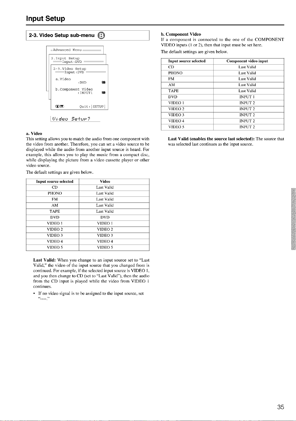
Input Setup
2-3. Video Setup sub-menu Q
Advanced Menu
2.1nput Setup
Input:DVD
2-3.Video Setup
Input:DVD
a.Video
:DVD
b.Component Video
:INPUTI
_ Quit:[SETUP 1
IUideo Setup?
b. Component Video
If a component is connected to the one of the COMPONENT
VIDEO inputs (1 or 2), then thai input must be set here.
The default settings are given below.
a. Video
This setting allows you to match the audio from one component wilh
the video from another. Therefore, you can set a video source to be
displayed while the audio from another input source is heard. For
example, this allows you to play the music from a compact disc,
while displaying the picture from a video cassette player or other
video source.
The default settings are given below.
Input source selected
CD
PHONO
FM
AM
TAPE
DVD
VIDEO 1
VIDEO 2
VIDEO 3
VIDEO 4
VIDEO 5
Video
Last Valid
Last Valid
Last Valid
Last Valid
Last Valid
DVD
VIDEO 1
VIDEO 2
VIDEO 3
VIDEO 4
VIDEO 5
Input source selected Component video input
CD Last Valid
PHONO Last Valid
EM Last Valid
AM Last Valid
TAPE Last Valid
DVD INPUT 1
VIDEO 1 INPUT 2
VIDEO 2 INPUT 2
VIDEO 3 INPUT 2
VIDEO 4 INPUT 2
VIDEO 5 INPUT 2
Last Valid (enables the source last selected): The source that
was selected last continues as the input source.
Last Valid: When you change Io an input source set to "Last
Valid," the video of the input source that you changed from is
continued. For example, if the selected input source is VIDEO 1,
and you then change Io CD (set to "Last Valid"), then the audio
from the CD input is played while the video from VIDEO 1
continues.
• If no video signal is Io be assigned to the input source, set
35
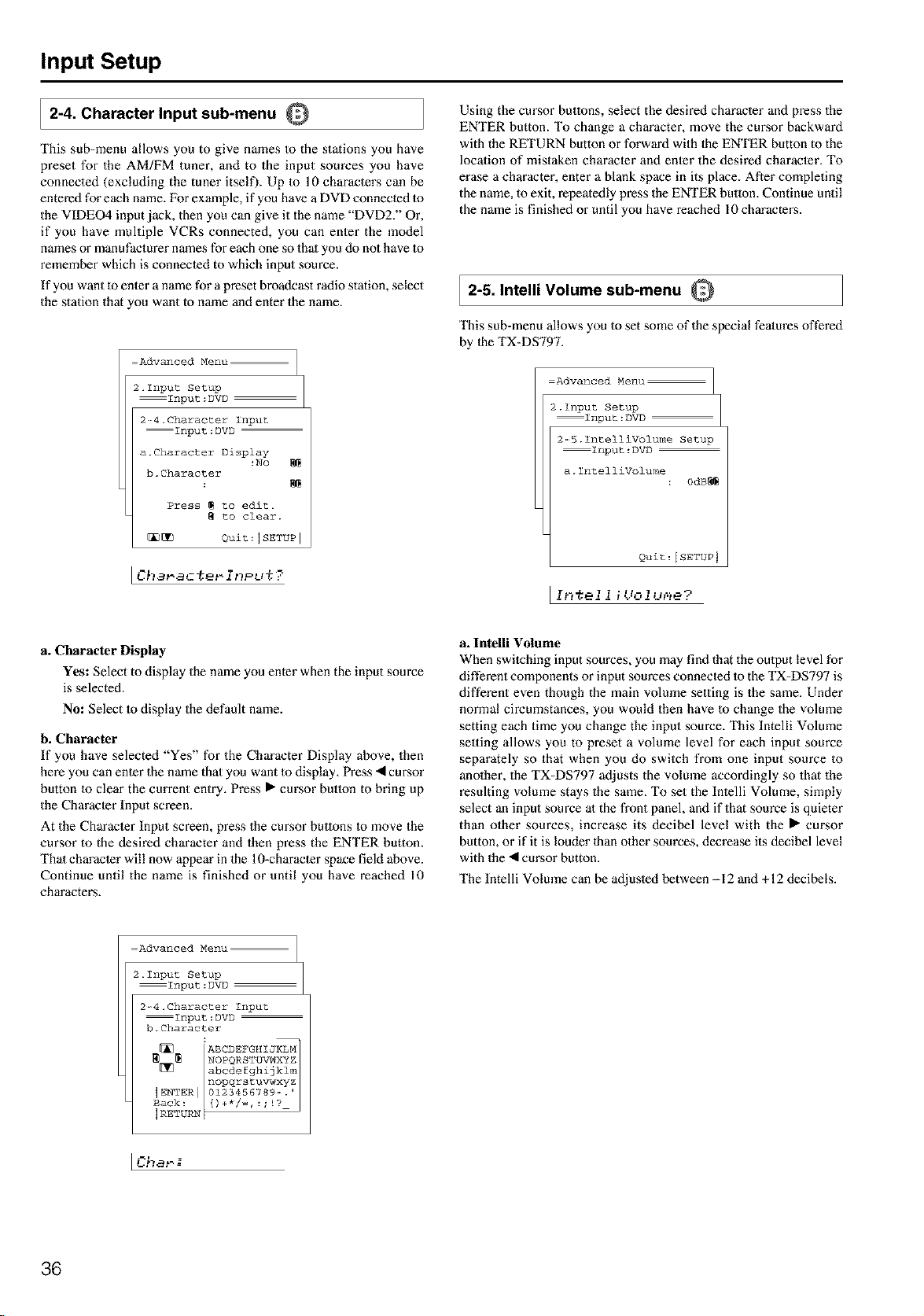
Input Setup
2-4. Character Input sub-menu Q
This sub-menu allows you to give names to the stations you have
preset for the AM/FM tuner, and to the input sources you have
connected (excluding the tuner itself). Up 1o 10 characters can be
entered for each name. For example, if you have a DVD connected Io
the VIDEO4 input jack, then you can give it the name "DVD2." Or,
if you have multiple VCRs connected, you can enter the model
names or manufacturer names for each one so thai you do not have Io
remember which is connected to which input source.
If you want to enter a name for a preset broadcast radio station, select
the station that you want to name and enter the name.
Using the cursor butlons, select the desired characler and press the
ENTER button. To change a character, move the CUl_Sorbackward
with the RETURN button or forward with the ENTER button to the
location of mistaken character and enter the desired character. To
erase a character, enter a blank space in its place. After completing
the name, to exit, repeatedly press the ENTER button. Continue until
the name is finished or until you have reached 10 characters.
2-5. Intelli Volume sub-menu Q
Advanced Menu
2.1nput Setup
Input:DVD
2-_4.Character Input
Input:DVD
a.Character Display
:No
b.Character
Press _ to edit.
to clear.
_ Quit:ISETUP ]
ICha_actat-i_P_,t?
This sub-menu allows you Io set some of the special features offered
by 1heTX-DS797.
Advanced Menu
2.Input Setup
Input:DVD
2-5.IntelliVolume Setup
Input:DVD
a. IntelliVolume
: 0dB_
Quit : I SETUP J
[ r.-_7-- 1 7 .11_1 ..... -_
a_rt _21_ r_.,i1flxx,i_.
a. Character Display
Yes: Select to display the name you enter when the input source
is selected.
No: Select to display the default name.
b. Character
If you have selected "Yes" for the Character Display above, then
here you can enter the name that you want to display. Press • cursor
button to clear the current entry. Press • cursor button to bring up
the Character Input screen.
At the Characler Input screen, press the cursor buttons Io move the
cursor to the desired character and then press the ENTER button.
Thai character will now appear in lhe 10-character space field above.
Continue until the name is finished or until you have reached 10
characters.
a. Inteni Volume
When switching input sources, you may find that the omput level for
different components or input sources connected 1o the TX-DS797 is
different even though the main volume setting is the same. Under
normal circumstances, you would then have to change the volume
setting each time you change the input source. This lntelli Volume
seuing allows you to preset a volume level for each input source
separately so that when you do switch from one input source to
anolher, the TX-DS797 adjusts the volume accordingly so that the
resulting volume stays the same. To set the lntelli Volume, simply
select an input source al the fl'ont panel, and if that source is quieter
than other sources, increase its decibel level with the • cm'sor
button, or if it is louder than other sources, decrease its decibel level
with the • cursor button.
The Intelli Volume can be adjusled between -12 and +12 decibels.
Advanced Menu
2.Input Setup
Input:DVD
2-4.Character Input
Input:DVD
b. Character
Icha,.--=
36
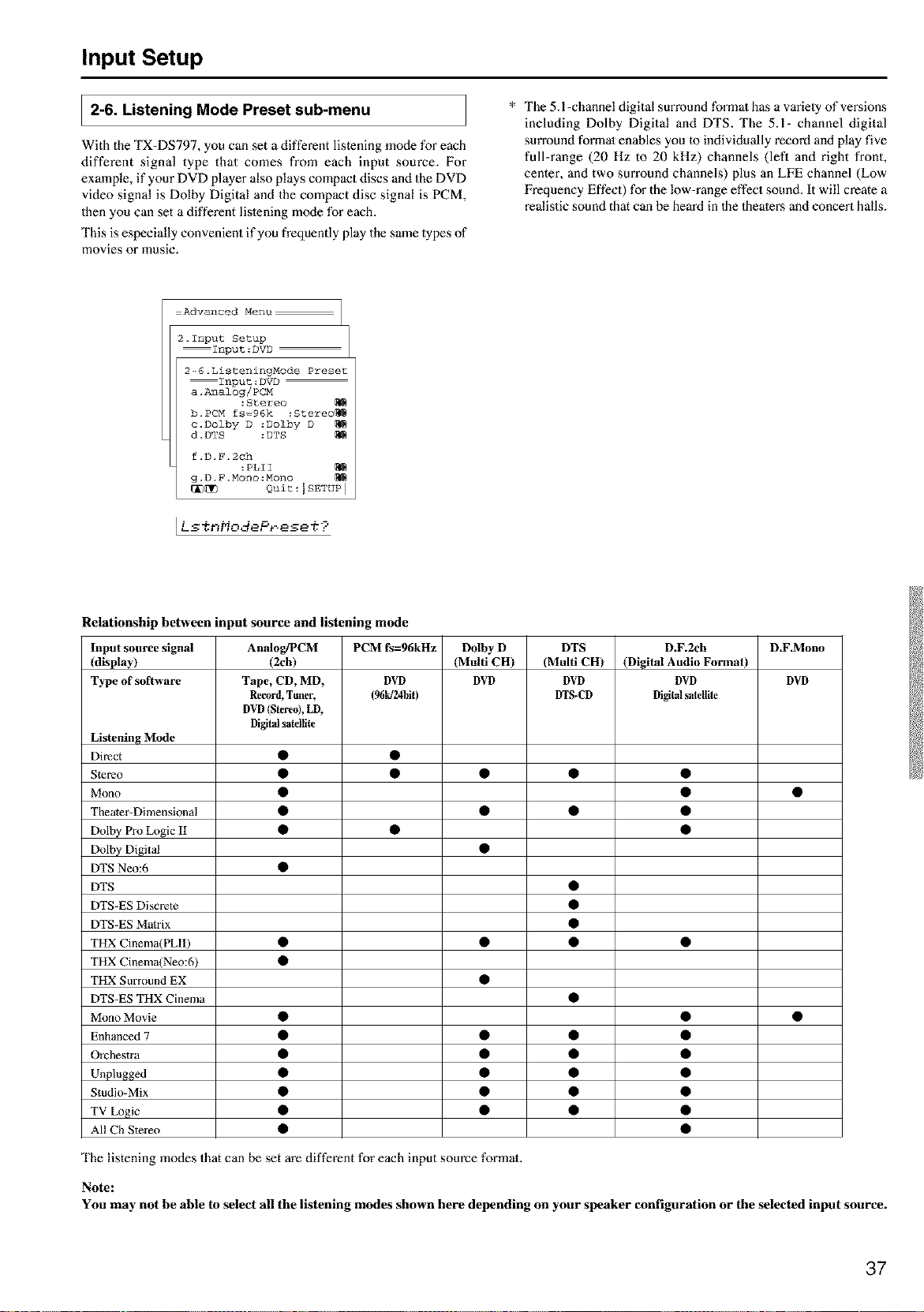
Input Setup
2-6. Listening Mode Preset sub-menu
With the TX-DS797, you can set a different listening mode for each
different signal type that comes from each input source. For
example, if your DVD player also plays compact discs and the DVD
video signal is Dolby Digital and the compact disc signal is PCM,
then you can set a different lislening mode for each.
This is especially convenient if you frequently play the same lypes of
movies or music.
* The 5.l-channel digital surround formal has a variely of revisions
including Dolby Digital and DTS. The 5.1- channel digital
surround formal enables you 1oindividually record and play five
full-range (20 Hz to 20 kHz) channels (left and right front,
center, and two surround channels) plus an LFE channel (Low
Frequency Effect) for the low-range effect sound. It will create a
realistic sound that can he heard in 1he 1heaters and concert halls.
Advanced Menu
2.1nput Setup
Input:DVD
2-_6.ListeningNode Preset
Input:DVD
a.l_lalog/PCN
:Stereo
b. PCM fs=96k :Stereo_
c.Dolby D :Dolby D
d. DTS :DTS
f.D.F.2ch
:PLII
g.D.F.Mono:Nono
_[_ Quit:ISETUP I
[Ls%_',,qodePr.ese ,¢9
Relationship between input source and listening mode
Input source signal
(display)
Type of software
AnaIog/PCM
(2ch)
Tape, CD, MD,
Record,Tuner,
DVD(Stereo),LD,
Digitalsatellite
PCM fs=96kHz
DVD
(96tff24bit)
Dolby D
(Multi CH)
DVD
DTS
(Multi CH)
DVD
DTS-CD
D.F.2ch
(Digital Audio Format)
DVD
Digitalsatellite
D.F_Mono
DVD
Listening Mode
Direct • •
Stereo • • • • •
Mono • • •
Theater-Dimensional • • • •
Dolby Pro Logic II • • •
Dolby Digital •
DTS Neo:6 •
DTS •
DTS-ES Discrete •
DTS-ES Matrix •
THX Cinema(PLI1) • • • •
THX Cinema(Neo:6) •
THX Surround EX •
DTS-ES THX Cinema •
Mono Movie • • •
Enhanced 7 • • • •
Orchestra • • • •
Unplugged • • • •
Studio-Mix • • • •
TV Logic • • • •
All Ch Stere() • •
The listening modes that can be set m'e different for each input source formal.
Note:
You may not he able to select all the listening modes shown here depending on your speaker configuration or the selected input source.
37
Input Setup
Input source signals
a. Analog/PCM
Analog sources consist of LP records, FM and AM broadcasts,
cassette tapes, and the such. PCM (Pulse Code Modulation) is one
form of digital audio signals and is recorded directly onto compact
discs and DVDs without compression.
b. PCM fs=96k
Set a listening mode for the input signal from digital PCM sources
recorded with a sampling rate of 96 kHz.
e. Dolby D (Dolby Digital)
Digital data with AC-3 compression and a maximum of 5.1-channel
surround sound. This source signal comes from DVDs and LDs that
have the m_ mark and therefore recorded for 5,l-channel output.
This source also comes from digital satellite broadcasts that support
Do[by Digital.
Dialog norm
Dialogue Normalization (Dialog Norm) is feature of Dolby
Digital. When playing back software that has been encoded in
Dolby Digital, sometimes you may see a brief message in the
front panel display that read Dialog Norm xdB ("x" being a
nmneric value). Dialogue Normalization serves m let you know
if the source material has been recorded at a higher or lower level
than usual. For example, if you see the message "Dialog Norm:
+4" in the front panel display, to keep the overall output level
constant just turn down the volume control by 4dB. In other
words, the source material that you are listening Io has been
recorded 4dB louder than usual If you do no1 see a message,
then no adjustment of the volume control is necessary.
r% • _ "1 _ .-'I L I -- .. a i .q
L': " "-- -': --'L-- ."'q "..i''..":" = ....u:....:
d. DTS
DTS (Digital Theater System) is compressed digital data with a
maximum 5.1-channel surround output that allows for an extremely
high-quality sound. This source signal requires a DVD player that
supports DTS output and comes from DVDs, compact discs, and
LDs thai have the _ mark.
f. D.F. 2 ch (Digital Format 2 channel)
2 channel digital signal (except for PCM) such as Dolby Digital.
DVD or LD in which the 2 channel sound are recorded may be this
type of input signal.
g. D.F. Mono (Digital Format Monaural)
Monaural digital signal (except for PCM) such as Do[by Digital.
DVD or LD in which the monaural sound are recorded may be this
type of input signal
Listening Modes
Mono
This mode is for playing old movies whose sound is recorded in
monaural or playing lefl and right channels separately in the movies
which contains the different language signals recorded into
individual channels. This mode also allows you to listen to the
multiplexed soundtracks on DVDs, and other media that have them.
Direct
This mode delivers pure sound with minimmn sound quality
adjustment and filtration, The sound recorded for the right and lefl
front channels is oulput to the right and left front speakez:s only and
not output Io the subwoofer.
Stereo
This mode has all input sound is output from the lefl and right front
speakers.
Subwoofer also can be used for playback.
T-D (Theater-Dimensional)
For the best enjoyment of your home theater, it is recommended that
you have at least front left and right speakers, a center speaker, and
surround left and right speakers. However, if you only have front lefl
and right speakers, you can enjoy multichannel audio by using this
mode.
This mode controls the characteristics of the sound that reaches each
ear to reproduce a multi-speaker setup. To receive the full effect,
there is an optimum listening position (sweet spot)_ Refer to the
explanation of the listening angle. In addition, if the reflective sound
components are large, it may be difficult to achieve the desired
result, so be sure to set up your system and listening position to
minimize reflective sound.
DOLBY PRO LOGIC II
This mode is a new generation 5-channel surround system that
provides performance between the 4-channel (left front, right front,
center, and monaural surround) Pro Logic Surround and the 5.1-
channel Dolby Digital Surround. This mode can be set to the Movie
mode designed for playing movies and the Music mode designed for
listening to music. In the Movie mode, the sun'ound channels, which
used to provide monaural output over only a narrow frequency
range, now provide complete stereo output over the full frequency
range. The result is movie viewing with a realistic feel of movement.
The Music mode uses the surround channels 1o provide a natural
sound space that cannot be provided with normal stereo output.
This mode can be used with VHS and DVD videos with the
I'I3_ mark and certain television programs. The Music mode
can be used with music compact discs and o_her stereo sources.
If no sm'round speakers are connected, then the surround sound is
divided and oulput from the front left and right channels (3 stereo).
Dolby D (Dolby Digital)
Used for playing Dolby Digital source.
38
Input Setup
DTS Neo:6
This mode is for 6.1 channel playback of 2 channel sources such as
PCM or analog sources. All 6 channel outputs are wide frequency
range with a great separation between the different channels.
This mode can be set to the Cinema mode designed for playing
movies and the Music mode designed for lislening to music.
The Cinema mode is good for movies. Reproduced surround sound
makes realistic feel of movement as 6.1 channel sources. This mode
can be used with VHS and television programs with stereo sound.
The Music mode uses the surround channels to provide a natural
sound space that cannol be provided with normal stereo oulput. This
mode can be used with music compact discs and other stereo
sources.
DTS
Used for playing DTS source.
DTS-ES Discrete 6.1
With the addition of the surround back channel, this new format has
all 6.1 channels recorded independently for a complelely discrele
digital format. Since all channels are recorded independently, high-
fidelity surround playback with the increased feeling of a separated
sound space is achieved.
DTS-ES Matrix 6.1
This format has the surround back channel matrix encoded and
inserted into the left and right surround channels so that at playback
the output for the left, right, and back surround channels are decoded
using a high-precision matrix decoder.
THX
This mode is for playing hack sources using THX.
For excellent fidelity when playing back THX sounds, it is
recommended Io use a THX-certified speaker syslem.
• THX Cinema
This is the conventional 5.l-channel THX format. This mode
should be used only when playing back sources that were mixed
for playback in large movie theater environments.
• THX Surround EX
"THX Surround EX - Dolby Digital Surround EX" is a joint
development of Dolby Laboratories and the THX division of
Lucasfilm Ltd.
In a movie theater, film soundtracks that have been encoded with
Dolby Digital Sun'ound EX technology are able to reproduce an
extra channel which has been added dm'ing the mixing of the
program. This channel, called Surround Back, places sounds
behind the listener in addition to the currently available fi'ont
left, front center, front right, surround right, surround lefL and
subwoofer channels.
This additional channel provides the opportunity for more
detailed imaging behind the lislener and brings more depth,
spacious ambience, and sound localization than ever before.
When released to the home consumer market, movies that were
created using the Dolby Digital Sun'ound EX technology, may
have a note to that effect on the packaging. A list of movies
created using this technology can be found on the Dolby web site
at http://www.dolby.com <http://www.dolby.com>.
This unit can play the 5.1 ch program in THX surround EX
mode, even if the program is not encoded in Dolby Digital
Surround EX format. For this kind of program, the sound from
sun'ound back channels depends on a program and may not fit to
your tasle.
Mono Movie
This mode is suitable for playing back monaural recording such as
old movie soundtracks. The center channel delivers the unprocessed
original sound, whereas the other channels deliver the center-
channel sound processed with the appropriate reverberatiom This
allows you to enjoy monaural sound with the atmosphere of a movie
theater.
Enhanced 7
Enhanced 7 intends to reproduce a natural surround environment by
using 7-channel speakers. The sound effects moving smoothly
toward the surround back. This mode is good for music and TV
sports programs.
Orchestra
This mode is appropriate for classical and opera music. The center
channel is cut and the surround channels are emphasized to widen
the stereo image. It will simulate the natural reverberation that is
created in large halls.
Unplugged
This mode is suitable for acoustical instrumental sounds, vocals, and
jazz music. By emphasizing the front stereo image, it will simulate
the acoustics that you would experience in fi'ont of the stage.
Studio-Mix
This mode is for rock and popular music. The lively sounds are
enhanced for a powerful acoustic image that simulates the feeling of
being in a club or rock concert.
TV Logic
This mode gives realistic acoustics to TV programs that are aired
from TV studios. It enhances the entire surround sound and clarity of
the conversation.
All Ch Stereo
This mode is designed for playing background music. The front,
surround, and surround back channels create a stereo image that
encompasses the entire area.
39
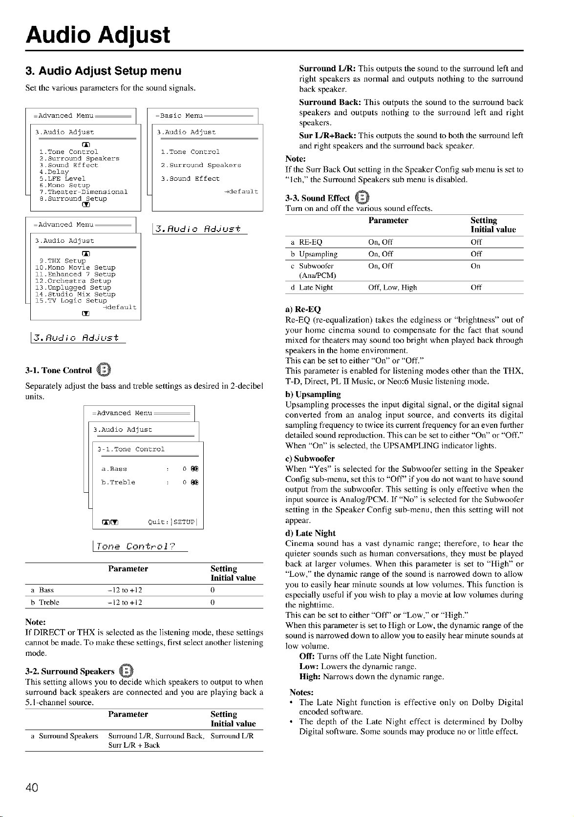
Audio Adjust
3. Audio Adjust Setup menu
Set the various parameters for the sound signals.
Advanced Menu:
3.Audio Adjust
l.Tone Control
2.Surround Speakers
3.Sound Effect
4.Delay
5.LFE Level
6.Mono Setup
7.Theater--Dimensi0nal
8.Surround Setup
Advanced Menu:
3.Audio Adjust
9.THX Setup
1O.Mono Movie Setup
ll.Enhanced 7 Setup
12.0rchestra Setup
13.Unplugged Setup
14.Studio Mix Setup
15.TV Logic Setup
-gdefault
17 ,_.. e,__
o,_u_lu Rd.iu_t
Basic Menu
3.Audio Adjust
1 .Tone Control
2 . Surr0und Speakers
3. Sound Effect
-Ide fault
[3. Rudio Rddu__;
3-1. Tone Control
Separ_ely adjust the bass and treble settings as desired in 2-decibel
units.
Advanced Menu
3.Audio Adjust
3-_l.Tone Control
a.Bass 0
b.Treble 0
[_[_ Quit=Ism'uPI
Parameter Setting
Initial value
a Bass --12 to +12 0
b Treble --12 to +12 0
Note:
If DIRECT or THX is selected as the listening mode, these settings
cannol be made. To make these settings, first select another listening
mode.
3-2. Surround Speakers
This setting allows you to decide which speakers to output to when
surround back speakers are connected and you are playing back a
5. l-channel source.
Parameter Setting
Initial value
a Smround Speakers Surround L/R, Smround Back, Surround [JR
Surr L/R + Back
Surround L/R: This outputs the sound to the surround left and
right speakers as normal and outputs nothing Io the surround
back speaker.
Surround Back: This outputs the sound to the sun'ound back
speakers and outputs nothing to the surround left and right
speakers.
Sur L/R+Back: This omputs the sound to bolh the sun'ound left
and right speakers and the sun'ound back speaker.
Note:
If 1he Surr Back Out seuing in the Speaker Config sub menu is set to
"lch," the Surround Speakers sub menu is disabled.
3-3. Sound Effect
Turn on and off the various sound effects.
Parameter Setting
Initial value
a RE-EQ On, Off Off
b Upsampling On, Off Off
c Subwoof_r On, Off On
(AnWPCM)
d Late Night Off, Low, High Off
a) Re-EQ
Re-EQ (re-equalization) takes the edginess or "brightness" out of
yore" home cinema sound to compensate for the fact that sound
mixed for theaters may sound too bright when played back through
speakers in the home enviromnent
This can be set 1o eilher "On" or "Off."
This parameter is enabled for lislening modes other than the THX,
T-D, Direct, PL II Music, or Neo:6 Music listening mode.
b) Upsampling
Upsampling processes the input digital signal or the digital signal
converted from an analog input source, and converts its digital
sampling frequency to twice its current frequency for an even further
detailed sound reproduction. This can be set to either "On" or "Off?'
When "On" is selected, the UPSAMPLING indicator lights.
c) Subwoofer
When "Yes" is selecled for the Subwoofer setting in the Speaker
Config sub-menu, set this to "Off" if you do no1 want to have sound
output from the subwoofer. This selling is only effective when the
input source is Analog/PCM. If "No" is selected for the Subwoofer
selling in the Speaker Config sub-menu, then this setting will not
appear.
d) Late Night
Cinema sound has a vast dynamic range; therefore, to hear the
quieter sounds such as human conversations, they must be played
back at larger volumes. When this parameter is set to "High" or
"Low," the dynamic range of the sound is narrowed down to allow
you to easily hear minute sounds al low volumes, This function is
especially useful if you wish to play a movie at low volumes during
the nigh.ime.
This can be set 1o either "Off" or "Low," or "High."
When this parameter is set 1o High or Low, the dynamic range of the
sound is narrowed down to allow you to easily hem" minute sounds at
low volume.
Off: Turns off 1he Late Night function.
Low: Lowers the dynamic range.
High: Narrows down the dynamic range.
Notes:
• The Late Night function is effective only on Dolby Digital
encoded soDware.
• The depth of the Late Night effect is determined by Dolby
Digital software. Some sounds may produce no or little effect.
4O
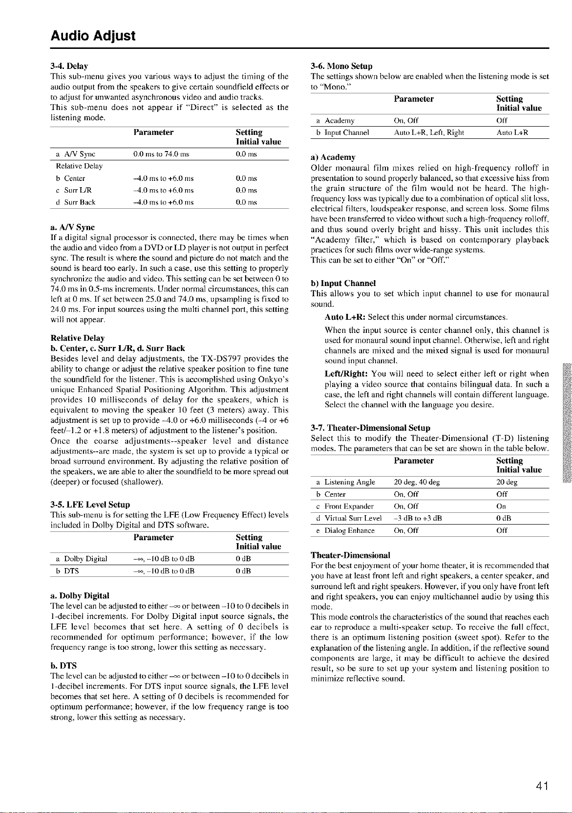
Audio Adjust
3-4. Delay
This sub-menu gives you various ways to adjust the timing of the
audio output from the speakers 1o give certain soundfield effects or
to adjust for unwanted asynchronous video and audio 1racks.
This sub-menu does not appear if "Direct" is selected as the
listening mode.
Parameter Setting
Initial value
a A!V Sync 0.0 ms m 74.0 ms 0d) ms
Relative Delay
b Cen_er --4.0 ms to +6d) ms 0d) ms
c Surr L/R --4.0 ms to +6.0 ms 0d) ms
d Surf Back --4.0 ms to +6.0 ms 0d) ms
a. A/V Sync
If a digital signal processor is connected, there may be times when
Ihe audio and video from a DVD or LD player is not output in perfect
sync. The result is where the sound and picture do not match and the
sound is heard too early. In such a case, use this setting to properly
synchronize the audio and video. This setting can be set between 01o
74.0 ms in 0.5-ms increments. Under normal circumstances, this can
left at 0 ms. If set between 25.0 and 74,0 ms, upsampling is fixed 1o
24.0 ms. For input sources using the multi channel port, this setting
will not appear.
Relative Delay
b. Center, c. Surr L/R, d. Surr Back
Besides level and delay adjustments, the TX-DS797 provides the
ability 1ochange or adjust the relative speaker position to fine tune
the soundfield for the listener, This is accomplished using Onkyo's
unique Enhanced Spatial Positioning Algorithm. This adjustment
provides 10 milliseconds of delay for the speakers, which is
equivalent to moving the speaker 10 feet (3 meters) away. This
adjustment is set up to provide M.0 or +6.0 milliseconds (M or +6
feet/-1.2 or +1,8 meters) of adjustment to the listener's position.
Once the coarse adjustments--speaker level and distance
adjustments--are made, the system is set up to provide a typical or
broad surround environment. By adjusting the relative position of
Ihe speakers, we are able to alter the soundfield to be more spread out
(deeper) or focused (shallower).
3-5. LFE Level Setup
This sub-menu is for setting the LFE (Low Frequency Effect) levels
included in Dolby Digital and DTS software.
Parameter Setting
Initial value
a Dolby Digital --_, -10 dB to 0 dB 0 dB
b DTS -_,-10 dB to 0 dB 0dB
a. Dolby Digital
The level can be adjusled to eilher-_ or between -10 lo 0 decibels in
l-decibel increments. For Dolby Digital input source signals, the
LFE level becomes that set here, A setting of 0 decibels is
recommended for optimum performance; however, if the low
frequency range is too strong, lower this setting as necessary.
b. DTS
The level can be adjusted to eilher-_ or between -10 Io 0 decibels in
l-decibel increments. For DTS input source signals, the LFE level
becomes that set here. A setting of 0 decibels is recommended for
opfimmn performance; however, if the low frequency range is too
strong, lower this setting as necessary.
3-6. Mono Setup
The settings shown below are enabled when the listening mode is set
to "Mono."
Parameter Setting
Initial value
a Academy On, Off Off
b Input Channel Auto L+R, Left, Right Auto L+R
a) Academy
Older monaural film mixes relied on high-frequency rolloff in
presentation to sound properly balanced, so that excessive hiss from
the grain structure of the film would not be heard. The high-
frequency loss was typically due to a combination of optical slit loss,
electrical fillers, loudspeaker response, and screen loss. Some fihns
have been transferred to video without such a high-frequency rolloff,
and thus sound overly bright and hissy. This unit includes this
"Academy filter," which is based on contemporary playback
practices for such films over wide-range systems.
This can be set to either "On" or "Off."
b) Input Channel
This allows you to set which input channel to use for monaural
sound.
Auto L+R: Select this under normal circumstances.
When the input source is center channel only, this channel is
used for monaural sound input channel. Otherwise, left and right
channels are mixed and the mixed signal is used for monaural
sound input channel.
Left/Right: You will need to select either left or right when
playing a video source that contains bilingual data. In such a
case, the lefi and right channels will contain different language.
Select the channel with the language you desire.
3-7. Theater-Dimensional Setup
Select this to modify the Theater-Dimensional (T-D) listening
modes. The parameters that can be set are shown in the table below.
Parameter Setting
Initial value
a Listening Angle 20 deg, 40 deg 20 deg
b Center On, Off Off
c Front Expander On, Off On
d Virtual Surr Level --3 dB m +3 dB 0 dB
e Dialog Enhance On, Off Off
Theater-Dimensional
For the best enjoyment of your home theater, it is recommended that
you have at least front left and right speakers, a center speaker, and
surround lefi and right speakers. However, if you only have front left
and right speakers, you can enjoy multichanne[ audio by using this
mode.
This mode controls the characteristics of the sound thai reaches each
ear to reproduce a multi-speaker setup. To receive the full effect,
there is an optimum listening position (sweet spot). Refer to the
explanation of the lislening angle. In addition, if the reflective sound
components are large, it may be difficult to achieve the desired
result, so be sure to set up your system and listening position to
minimize reflective sound.
41
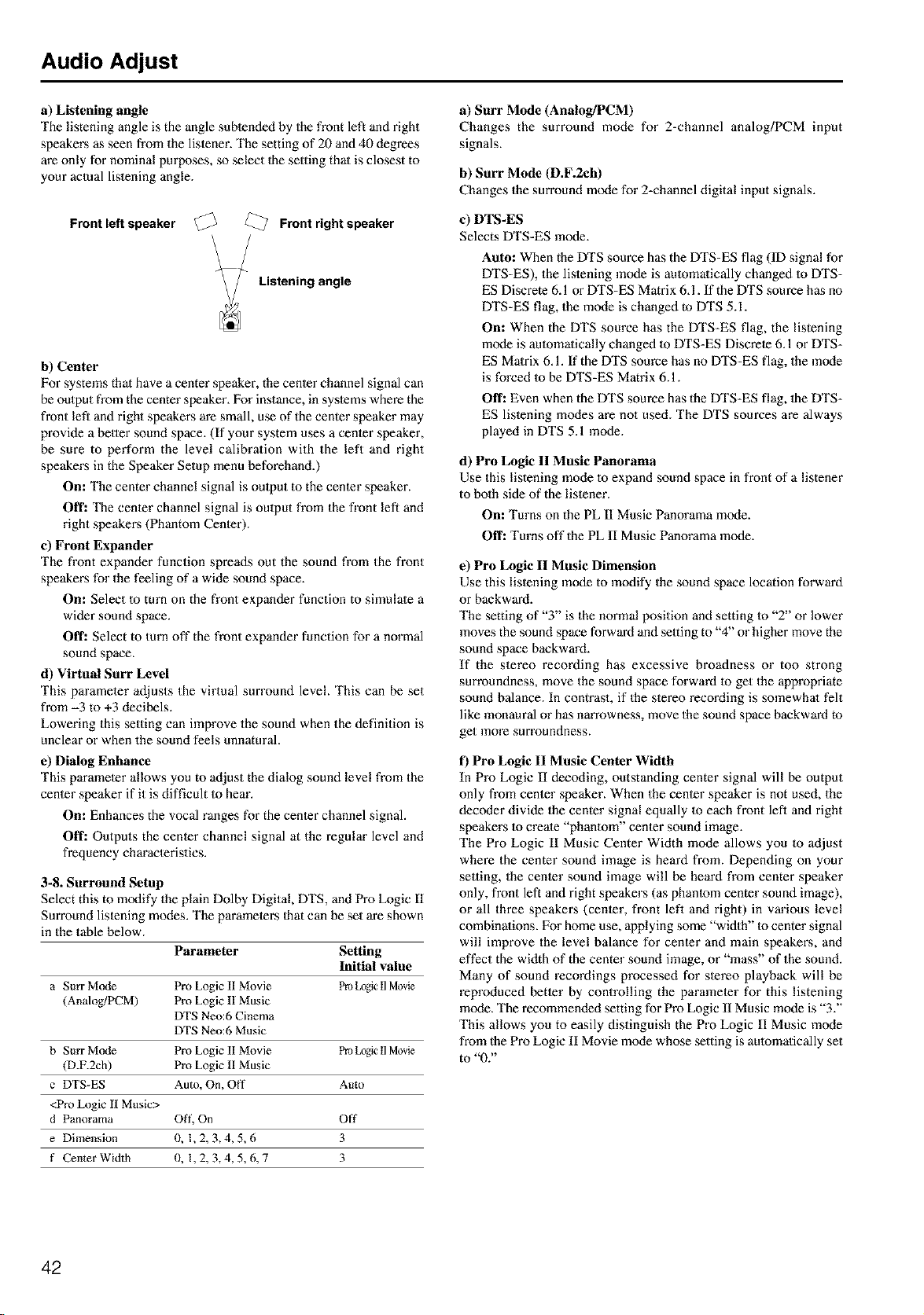
Audio Adjust
a) Listening angle
The listening angle is the angle subtended by the front left and right
speakers as seen from the listener. The setting of 20 and 40 degrees
are only for nominal purposes, so select 1he setting that is closest to
your actual lislening angle.
Front left speaker
Front right speaker
Listening angle
b) Center
For systems that have a center speaker, the center channel signal can
be output from the center speaker. For instance, ill syslems where the
front left and right speakers are small, use of the center speaker may
provide a better sound space. (If your system uses a center speaker,
be sure to perform the level calibration with the left and right
speakers in the Speaker Setup menu beforehand.)
On: The center channel signal is oulput to the center speaker.
Off: The center channel signal is oulpot from the fi'ont left and
right speakers (Phantom Center).
e) Front Expander
The front expander function spreads out the sound from the front
speakers for the feeling of a wide sound space.
On: Select to turn on the front expander function to simulate a
wider sound space.
Off: Select to turn off the front expander function for a normal
sound space.
d) Virtual Surr Level
This parameler adjusts the virtual surround level. This can be set
from -3 to +3 decibels.
Lowering this setting can improve the sound when the definition is
unclear or when the sound feels unnatural.
e) Dialog Enhance
This parameler allows you to adjust the dialog sound [eve[ from the
center speaker if it is difficult Io hear.
On: Enhances the vocal ranges for the center channel signal.
Off: Outputs the center channel signal at the regular level and
frequency characteristics.
3-8. Surround Setup
Select this to modify the plain Do]by Digital DTS, and Pro Logic II
Surround listening modes. The parameters 1hat can be set are shown
in the table below.
Parameter Setting
Initial value
a Star Mode Pro Logic II Movie Pro LogicII Movie
(Analog/PCM) Pro Logic II Music
DTS Neo:6 Cinema
DTS Neo:6 Music
b Surr Mode Pro Logic II Movie Pro LogicII Movie
(D.F.2ch) Pro Logic II Music
c DTS-ES Aum, On, Off Auto
<Pro Logic 1[ Music>
d Panorama Oft', On Off
e Dimension 0, 1,2,3,4,5,6 3
f Center Width 0, 1,2,3,4,5,6,7 3
a) Surr Mode (Analog/PCM)
Changes the surround mode for 2=channel analog/PCM input
signals.
b) Surr Mode (D.F.2eh)
Changes the surround mode for 2=channel digital input signals.
e) DTS-ES
Selects DTS-ES mode.
Auto: When the DTS source has the DTS=ES flag (ID signal for
DTS=ES), the lislening mode is aulomatically changed 1o DTS=
ES Discrete 6.1 or DTS=ES Matrix 6.1. If the DTS source has no
DTS=ES flag, the mode is changed to DTS 5.1.
On: When the DTS source has the DTS-ES flag, the listening
mode is aulomatieally changed to DTS=ES Discrete 6.1 or DTS=
ES Matrix 6.1. If the DTS source has no DTS=ES flag, the mode
is forced to be DTS=ES Matrix 6.1.
Off: Even when the DTS source has the DTS=ES flag, 1he DTS-
ES listening modes are not used. The DTS sources are always
played in DTS 5.1 mode.
d) Pro Logic II Music Panorama
Use this listening mode to expand sound space in front of a listener
to both side of the listener.
Onz Turns on the PL II Music Panorama mode.
Offz Turns off the PL II Music Panorama mode.
e) Pro Logic II Music Dimension
Use this lislening mode to modify the sound space location forward
or backward.
The setting of "3" is the normal position and setting to "2" or lower
moves the sound space forward and seldng to "4" or higher move the
sound space backward.
If the stereo recording has excessive broadness or too strong
surroundness, move the sound space forward to get the appropriate
sound balance. In contrast, if the stereo recording is somewhal felt
like monaural or has narrowness, move the sound space backward to
get more surroundness.
f) Pro Logic II Music Center Width
In Pro Logic II decoding, outstanding center signal will be output
only from center speaker. When the cenler speaker is not used, the
dec(xter divide the center signal equally to each front lefl and right
speakers 1ocreate "phantom" cenler sound image.
The Pro Logic II Music Center Width mode allows you to adjust
where the center sound image is heard from. Depending on your
selling, the cenler sound image will be heard from center speaker
only, front left and right speakers (as phanlom center sound image),
or all three speakers (cenler, front lefl and right) in various level
combinalions. For home use, applying some "width" Io center signal
will improve the level balance for cenler and main speakers, and
effect the width of the center sound image, or "mass" of the sound.
Many of sound recordings processed for slereo playback will be
reproduced betler by controlling the parameter for this listening
mode. The recommended setting for Pro Logic II Music mode is "3."
This allows you to easily distinguish the Pro Logic ll Music mode
from the Pro Logic II Movie mode whose setting is aulomatically set
to "0."
42
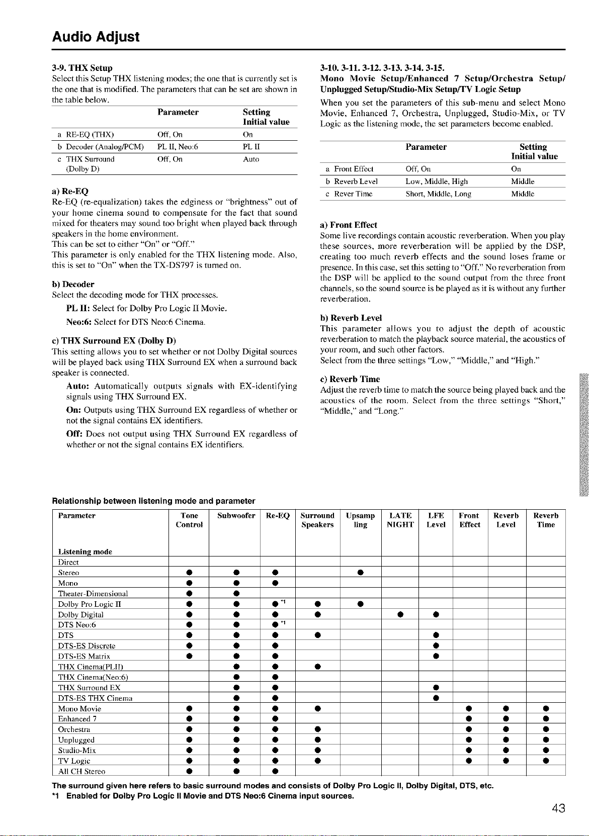
Audio Adjust
3-9. THX Setup
Select this Setup THX lislening m(xtes; the one thai is currently set is
the one thai is modified. The paramelers thai can be set are shown in
the table below.
Parameter Setting
Initial value
a RE-EQ (THX) Off, On On
b Decoder (Ana!og/PCM) PL lI, Neo:6 PL lI
c THX Surround Off, On Auto
(Dolby D)
a) Re-EQ
Re-EQ (re-equalization) takes the edginess or "brightness" out of
your home cinema sound Io compensate for the fact that sound
mixed for thealers may sound 1oo bright when played back through
speakers in the home environment.
This can be set to either "On" or "Off."
This parameler is only enabled for the THX listening mode. Also,
this is set Io "On" when the TX-DS797 is turned on.
b) Decoder
Select the decoding mode for THX processes.
PL II: Select for Dolby Pro Logic II Movie.
Neo:6: Select for DTS Neo:6 Cinema.
e) THX Surround EX (Dolby D)
This setting allows you to set whether or not Dolby Digital sources
will be played back using THX Surround EX when a surround back
speaker is connecled.
Auto: Automatically outputs signals with EX-identifying
signals using THX Surround EX.
On: Outputs using THX Surround EX regardless of whether or
not the signal contains EX identifiers.
Off: Does not output using THX Surround EX regardless of
whether or not the signal contains EX identifiers.
3-10. 3-11.3-12. 3-13. 3-14. 3-15.
Mono Movie Setup/Enhanced 7 Setup/Orchestra Setup/
Unplugged Setup/Studio-Mix Setup/TV Logic Setup
When you set the parameters of this sub-menu and select Mono
Movie, Enhanced 7, Orchestra, Unplugged, Studio-Mix, or TV
Logic as the listening mode, the set pm'ameters become enabled.
Parameter Setting
Initial value
a Front Eft_ct Off, On On
b Reverb Level Low, Middle, High Middle
c ReverTime Short, Middle, Long Middle
a) Front Effect
Some live recordings contain acoustic reverberalion. When you play
these sources, more reverberation will be applied by the DSP,
creating too much reverb effects and the soond loses frame or
presence. In this case, set this setting 1o"Off," No reverberation from
the DSP will be applied to the sound output from the three front
channels, so the sound source is be played as it is without any furlher
reverberation.
b) Reverb Level
This parameter allows you to adjust the depth of acoustic
reverberalion 1o match the playback source material, the acoustics of
your room, and such other faclors.
Select from the three settings "Low," "Middle," and "High."
e) Reverb Time
Adjust the reverb time to match the source being played back and the
acoustics of the room. Select from the three settings "Short,"
"Middle," and "Long."
Relationship between listening mode and parameter
Parameter Tone Subwoofer Re-EQ Surround Upsamp LATE LFE Front Reverb
Control Speakers ling NIGHT Level Effect Level
Listening mode
Direct
Stereo • • •
Mono • • •
Theater-Dimensional • •
Dolby Pro Logic II • • • "_
Dolby Digital • • •
DTS Neo:6 • • • "_
DTS • • •
DTS-ES Discrete • • •
DTS-ES Matrix • • •
THX CinemalPLII) • •
THX Cinema(Neo:6) • •
THX Surround EX • •
DTS-ES THX Cinema • •
Mono Movie • • •
Enhanced 7 • • •
Orchestra • • •
Unplugged • • •
Studio-Mix • • •
TV Logic • • •
All CH Stereo • • •
Reverb
Time
The surround given here refers to basic surround modes and consists of Dolby Pro Logic II, Dolby Digital, DTS, etc.
"1 Enabled for Dolby Pro Logic II Movie and DTS Neo:6 Cinema input sources.
43
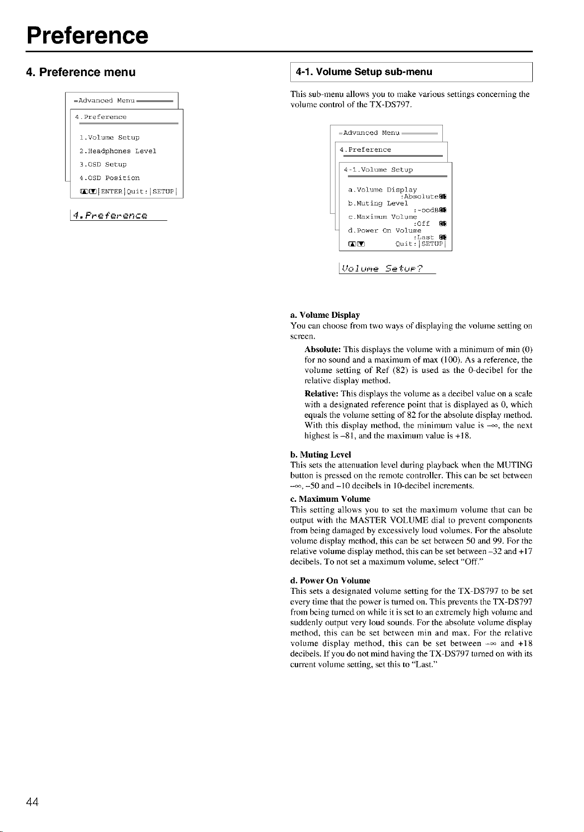
Preference
4. Preference menu
Advanced Menu
4.Preference
l.Volume Setup
2.Headphones Level
3.0SD Setup
4.0SD Position
_[_IENTERIQuit:ISETUPI
4. P_e {et-enffe
4-1. Volume sub-menu
Setup
This sub-menu allows you tomake various settings concerning the
volume control of the TX-DS797.
Advanced Menu
4.Preference
4-l.Volume Setup
a. Volume Display
:Abs01ute_
b.Muting Level
:-00dB_
c.Maximum Volume
:Off
d. Power On Volume
:Last
_ Quit:ISETUP 1
a. Volume Display
You can choose from two ways of displaying the volmne setting on
screen.
Absolute: This displays the volmne with a minimum of rain (0)
for no sound and a maximum of max (100). As a reference, the
volume setting of Ref (82) is used as the 0-decibel for the
relative display method.
Relative: This displays the volume as a decibel value on a scale
with a designated reference point that is displayed as 0, which
equals the volume setting of 82 for the absolute display method.
With this display method, the minimum value is _, the next
highest is -81, and the maximmn value is +18.
b. Muting Level
This sets the attenuation level during playback when the MUTING
button is pressed on the remote controller. This can be set between
-_, -50 and -10 decibels in 10-decibel increments.
c. Maximum Volume
This setting allows you to set the maximum volume that can be
omput with the MASTER VOLUME dial to prevent components
from being damaged by excessively loud volumes. For the absolute
volume display method, this can be set between 50 and 99. For the
relative volmne display method, this can be set between -32 and +17
decibels. To nol set a maximum volume, select "Off."
d. Power On Volume
This sets a designaled volume setting for the TX-DS797 to be set
every time that the power is turned on. This prevents the TX-DS797
from being turned on while it is set 1o an extremely high volmne and
suddenly omput very loud sounds. For the absolute volume display
method, this can be set between rain and max. For the relative
volume display method, this can be set between -_ and +18
decibels. If you do nol mind having the TX-DS797 turned on with its
current volume setting, set this to "Last?'
44
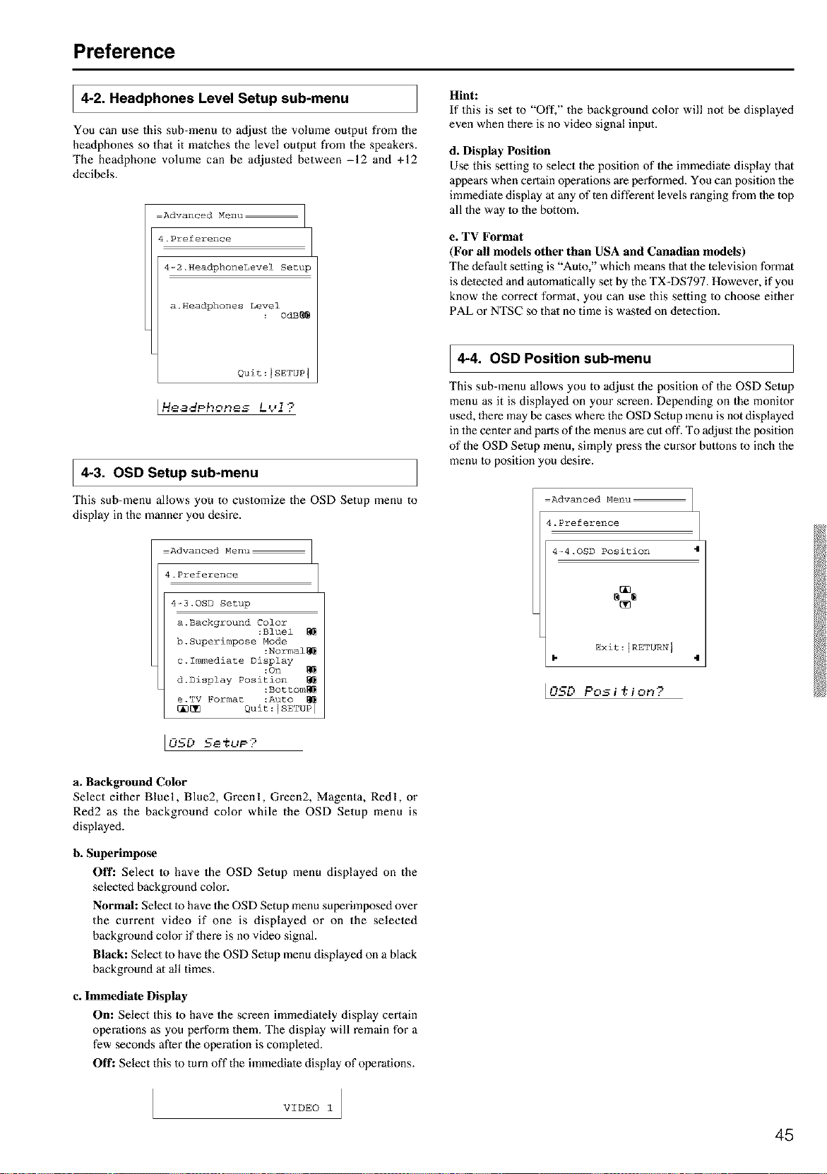
Preference
4-2. Headphones Level Setup sub-menu
You can use this sub-menu to adjust the volume oulput from the
headphones so that it matches the level output from the speakers.
The headphone volume can be adjusted between -12 and +12
decibels.
Advanced Menu
4.Preference
4-2.HeadphoneLevel Setup
a.Headphones Level
0dB_
Quit:JSETUP 1
[Ho adPhones L<.'J ?
4-3. OSD sub-menu
Setup
This sub-menu allows you to customize the OSD Setup menu to
display in the manner you desire.
Advanced Menu
4.Preference
4-_3.0SD Setup
a. Baokground Color
:Bluel
h. Superimpose Mode
:Normal_
c. Immediate Display
:On
d.Display Position
:Bottom_
e.TV Format :Auto
[_ Quit:ISETUP I
Hint:
If this is set to "Off," the background color will not be displayed
even when there is no video signal input.
d. Display Position
Use this setting Io select the position of the immediate display that
appears when certain operations are performed. You can position the
immediate display al any of ten different levels ranging from the top
all the way Io the bottom.
e. TV Format
(For all models other than USA and Canadian models)
The default setting is "Auto," which means thai the television format
is detected and amomalically set by the TX-DS797. However, if you
know the correct format, you can use this setting Io choose either
PAL or NTSC so that no time is wasted on detection.
4-4. OSD Position sub-menu
This sub-menu allows you to adjust the position of the OSD Setup
menu as it is displayed on your screen. Depending on the monitor
used, there may be cases where the OSD Setup menu is not displayed
in the center and parts of the menus are cut off, To adjust the position
of the OSD Setup menu, simply press the cursor buttons to inch the
menu Io position you desire.
Advanced Menu
4.Preference
4-4.OSD Position 4
Exit:IRETURN j
4
I0SD Pos i ,+.i on?
a. Background Color
Select either Bluel, Blue2, Greenl, Green2, Magenta, Redl, or
Red2 as the background color while the OSD Setup menu is
displayed.
h. Superimpose
Off: Select to have the OSD Setup menu displayed on the
selected background color.
Normal: Select to have the OSD Setup menu superimposed over
the current video if one is displayed or on the selected
background color if there is no video signal.
Black: Select to have the OSD Setup menu displayed on a black
background at all times.
c. Immediate Display
On: Select this to have the screen immediately display certain
operations as you perform them. The display will remain for a
few seconds after the operation is completed.
Off: Select this Io turn off the immediate display of operations.
VIDEO 1
45
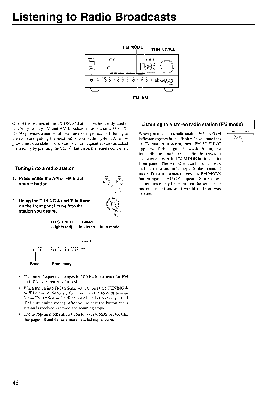
Listening to Radio Broadcasts
m
@_ o ....8
FM AM
One of the features of the TX-DS797 thai is most frequently used is
its ability to play FM and AM broadcast radio stations. The TX=
DS797 provides a nmnber of lislening modes perfect for lislening to
the radio and getting the most out of your audio system. Also, by
presetting radio stalions that you listen to frequently, you can select
them easily by pressing the CH +/= button on the remole controller.
I Tuning into a radio station
1. Press either the AM or FM input
source button.
2. Using the TUNING • and • buttons
on the front panel, tune into the
station you desire.
i.-- .r,.,t
"FM STEREO" Tuned
(Lights red) in stereo Auto mode
Listening to stereo radio station
(FMmode)
a
When you tune into a radio station, • TUNED < ...........
indicator appears in the display. If you tune into _v'\
an FM station in stereo, then "FM STEREO"
appears. If the signal is weak, it may be
impossible to tune into the station in slereo. In
such a case, press tile FM MODE button on the
front panel. The AUTO indicalion disappears
and the radio station is output in the monaural
mode. To return Io stereo, press the FM MODE
button again. "AUTO" appears. Some inter=
station noise may be heard, but the sound will
not cut in and out as it would if stereo was
selected.
Band Frequency
• The tuner frequency changes in 50 kHz increments for FM
and 10 kHz increments for AM.
• When tuning into FM stations, you can press the TUNING •
or • butlon continuously for more than 0.5 seconds to scan
for an FM station in the direction of the button you pressed
(FM aulo tuning mode). After you release the button and a
stalion is received in stereo, the scanning stops.
• The European model allows you to receive RDS broadcasts.
See pages 48 and 49 for a more detailed explanalion.
46
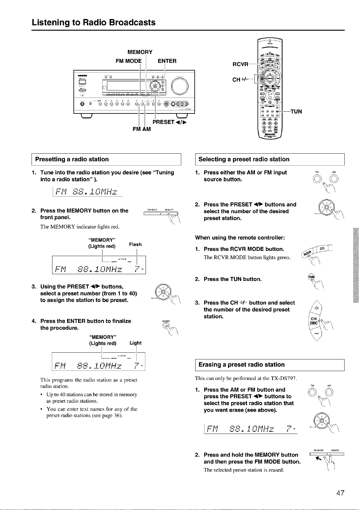
Listening to Radio Broadcasts
MEMORY
I
FM MODE I ENTER
o ...........
// PRESET<I/I_
FM AM
RCVR_
CH +/=_
)®_ TUN
-===
I Presetting radio station
a
1. Tune into the radio station you desire (see "Tuning
into a radio station" ).
i- i'i C,_Z, . ..L iJFii'=i._.
2. Press the MEMORY button on the
front panel.
The MEMORY indicator lights red.
"MEMORY"
(Lights red) Flash
3. Using the PRESET _ buttons,
select a preset number (from 1 to 40)
to assign the station to be preset.
4. Press the ENTER button to finatize
the procedure.
"MEMORY"
(Lights red) Light
This programs the radio station as a preset
radio station.
• Up to 40 stations can be stored in memory
as preset radio stations.
• You can enter text names for any of the
preset radio stations (see page 36).
I Selecting a preset
radio station
1. Press eitherthe AM or FM input
source button.
2. Press the PRESET _ buttons and
select the number of the desired
preset station.
When using the remote controller:
t. Press the RCVR MODE button.
The RCVR MODE button lights green.
2. Press the TUN button.
3. Press the CH _= button and select
the number of the desired preset
station.
I Erasing a preset radio station
This can only be performed at the TX-DS797.
t. Press the AM or FM button and
press the PRESET _ buttons to
select the preset radio station that
you want erase (see above).
[Fhi 88o .-Oh1'-- "-
2. Press and hold the MEMORY button
and then press the FM MODE button.
The selected preset station is erased.
47
Listening to RDS broadcasts (Europeanmodels only)
I Listening to RDS broadcasts
RDS reception is available only on the European model and only in
areas where RDS broadcasts are available.
What is RDS?
RDS stands for Radio Data Syslem and is a type of FM broadcasting.
RDS was developed within the European Broadcasting Union
(EBU) and is available in most European countries. Many FM
broadcasting stations now transmit the RDS signals, which provide
the additional information required. RDS provides you with various
services so that you can choose a station that broadcasts your
favorite categories of music, news, or other information.
There are three main classificalions of RDS broadcasts. Though they
can be tuned inlo by using the Tuning butlons as normal stations,
RDS broadcasts allow you to scan for stations of the type and
classificalion for which you are looking. This makes it much easier
for you to find the station you want (see "Performing a PTY scan"
and "Performing a TP scan" on page 49). The three main
classifications are explained below.
RT: Radio Text
When an RDS stalion broadcasting RT information is selected, the
text information received from the station is displayed.
PTY: Program Type
When an RDS station broadcasting PTY information is selected, the
station type (classification) is displayed.
TP: Traffic Program
When an RDS station broadcasting TP information is selected,
traffic information will be broadcasled periodically.
Notes:
• In some cases, the characters displayed on the display of the TX-
DS797 may not be exactly 1he same as the ones broadcast by the
radio station. Also, unusual characters may appear on the display
if the TX-DS797 receives characters that cannot be displayed
correctly. This is not a malfunction.
• When an RDS station broadcasting PS information is selected,
the name of 1he station is displayed instead of the frequency.
PTY program types Europe
in
The text given in parenthesis is what is actually displayed on the TX-
DS797.
None (NONE):
No program type.
News reports (NEWS):
Repo_s on current events and happenings.
Current affairs (AFFAIRS):
Topical reporting of era'rent affail:% often with a wider range of
topics than news reports.
Information (INFO):
General information such as weather forecasts, consumer affair,s,
medical help, etc.
Sport (SPORT):
Live spo_s action, sports news, and interviews.
Education (EDUCATE):
Formal educational programs.
Drama (DRAMA):
Radio plays and serials.
Culture (CULTURE):
Cultural programs (including religious affaii_s).
Science and technology (SCIENCE):
Programs about the natural sciences and technology.
Varied (VARIED):
Speech=based programs not covered by the above categories (e.g.,
quizzes, panel games, and comedy).
Pop music (POP M):
Popular commercial music, usually from past or present sales charts
(e.g., Top 40).
Rock music (ROCK M):
Popular music with an alternative appeal, oflen not appearing on
sales charts.
Middle of the road music (M.O.R. M):
Easy lislening music (as opposed to Pop, Rock, or Classical).
Light classics (LIGHT M):
Classical music for general rather than specialist appreciation.
Serious classics (CLASSICS):
Performances of major orchestral works, symphonies, chamber
music, ete. (including the Grand Opera).
Other music (OTHER M):
Music styles not covered by the above categories (e.g., Jazz, Rhythm
& Blues, Folk, Country, and Reggae).
• Alarm (ALARM):
When an RDS station is making an emergency broadcast, this
ALARM will flash on the display.
48
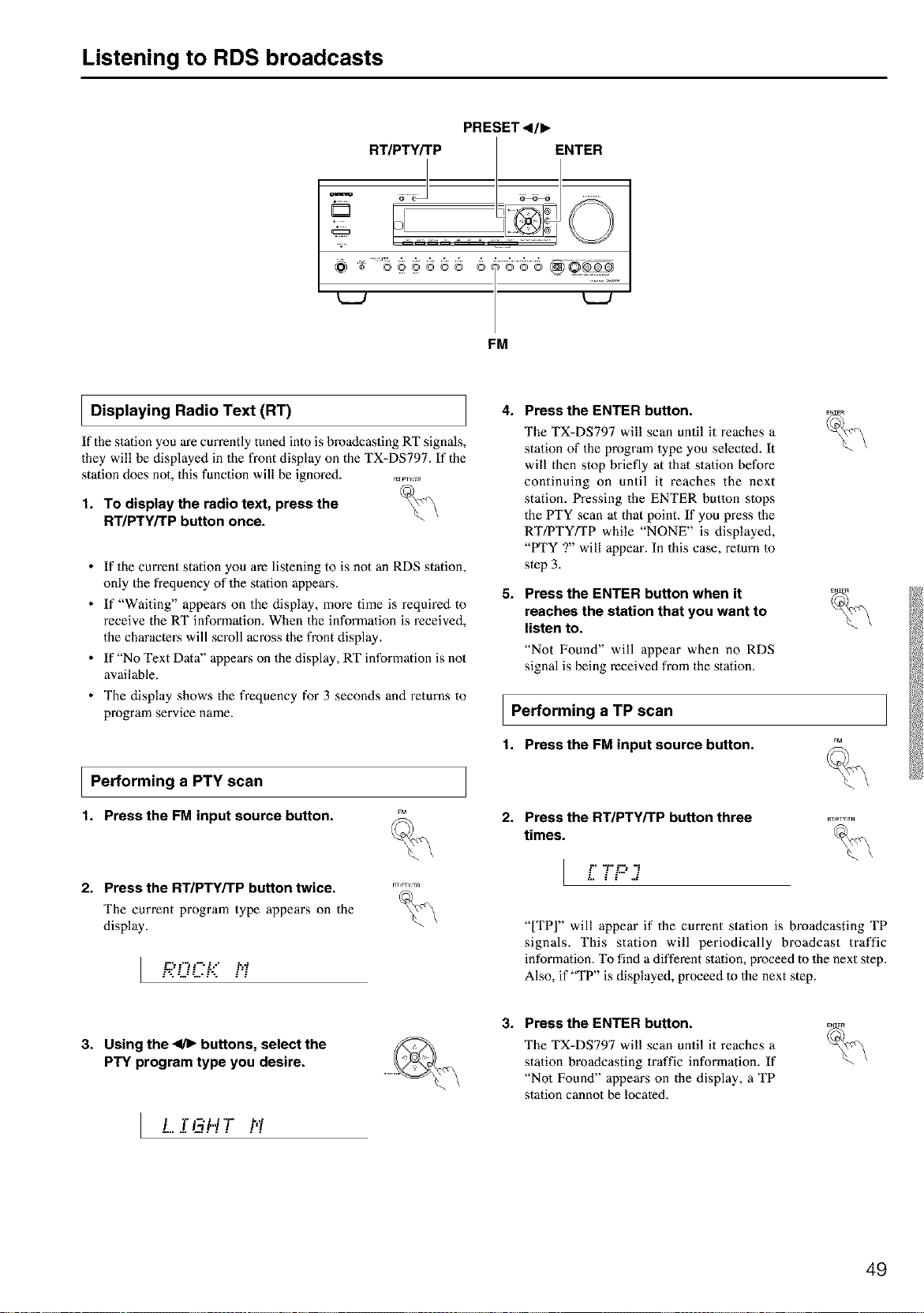
Listening to RDS broadcasts
PRESET<l,
RT/PT_P_ _:_ENTER
FM
I Displaying Radio Text (RT)
If the station you are currently tuned into is broadcasting RT signals,
they will be displayed in the front display on the TX-DS797. If the
station does not, this function will be ignored. R_........
1. To display the radio text, press the _
RT/PTY/TP button once.
• If the current station you are listening to is not an RDS station,
only the frequency of the station appem_s,
• If "Waiting" appears on the display, more time is required to
receive the RT information, When the information is received,
the characters will scroll across the front display.
• If "No Text Data" appem_s on the display, RT information is not
available.
• The display shows the frequency for 3 seconds and returns to
program service name.
I Performing a scan
PTY
1. Pressthe FM input source button.
2. Press the RT/PTY/TP button twice. _
The current program type appears on the _
display.
I ROC-::.i_
4. Press the ENTER button.
5.
The TX-DS797 will scan until it reaches a
station of the program type you selected. It
will then stop briefly at that station before
continuing on until it reaches the next
station. Pressing the ENTER butlon slops
the PTY scan ;11that point. If you press the
RT/PTY/TP while "NONE" is displayed,
"H'Y ?" will appear. In this case, return Io
step 3.
Press the ENTER button when it
reaches the station that you want to
listen to.
"Not Found" will appear when no RDS
signal is being received from the station.
I Performing a scan
TP
1. Pressthe FM input source button.
2. Press the RT/PTWTP button three
times.
l .., ..i=...=:-..
FnPTV:T_
%
"[TPI" will appear if the current station is broadcasting TP
signals, This station will periodically broadcast traffic
information. To find a different station, proceed to the next step.
Also, if "TP" is displayed, proceed Io Ihe next step.
3. Using the _ buttons, select the
PTY program type you desire.
I L..IGWT hi
3. Press the ENTER button.
The TX-DS797 will scan until it reaches a
station broadcasting traffic information. If
"No1 Found" appears on the display, a TP
station cannot be locale&
49
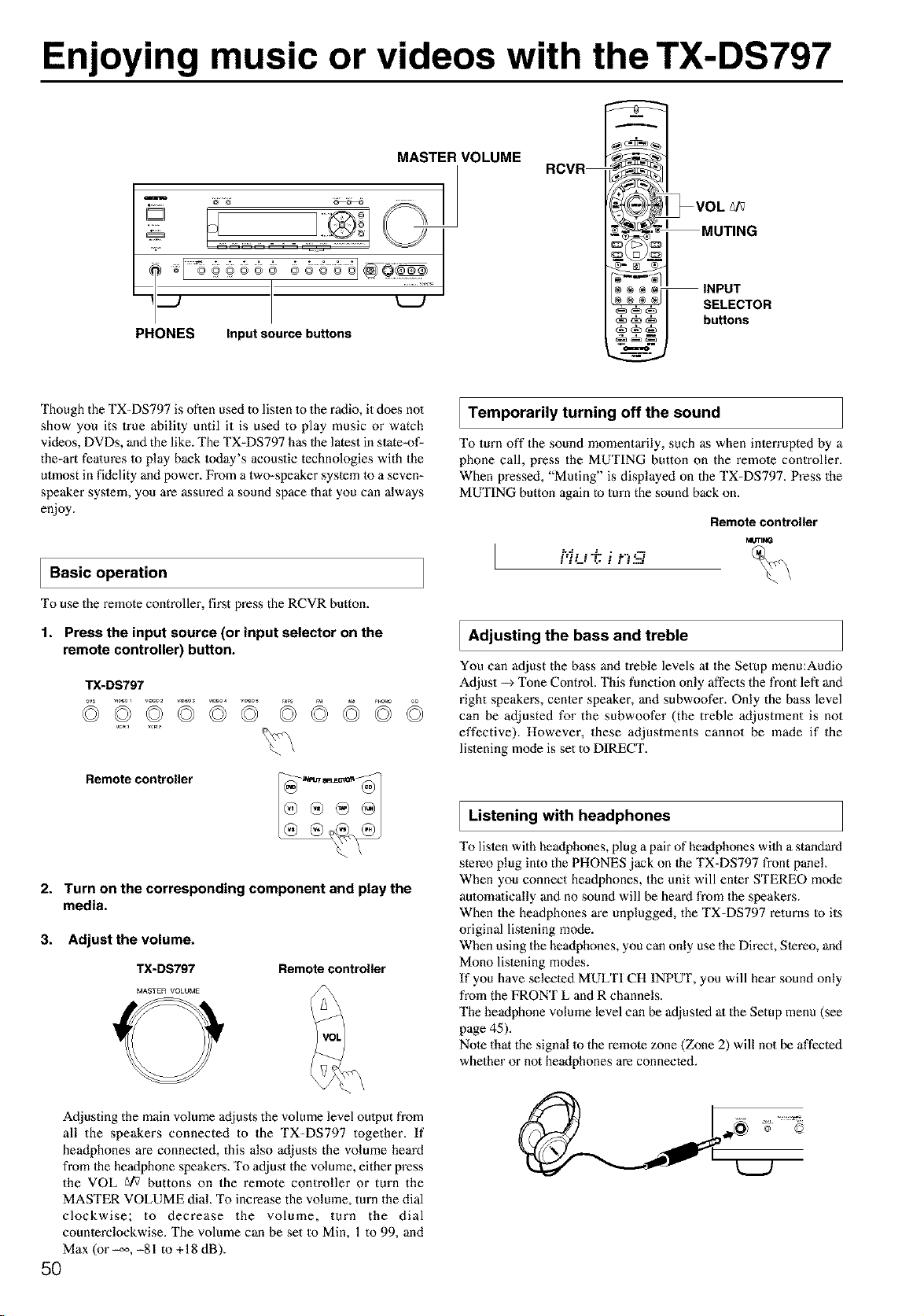
Enjoying music or videos with the TX-DS797
MASTER VOLUME
PHONES Input source buttons
RCVR
* _VOL _/_
MUT,NG
0© 1
® ÷ _ INPUT
I SELECTOR
.uttons
Though the TX=DS797 is often used to listen 1o the radio, it does no1
show you its true ability until it is used to play music or watch
videos, DVDs, and the like. The TX=DS797 has 1he latest in state=of-
the=art fealures Io play back Ioday's acoustic technologies with the
utmost in fidelity and power. From a two=speaker system 1o a seven=
speaker system, you are assured a sound space that you can always
enjoy.
I Basic operation
To use the remote controller, first press the RCVR button.
1. Press the input source (or input selector on the
remote controller) button.
Remote controller
2. Turn on the corresponding component and play the
media.
3. Adjust the volume.
TX-DS797 Remote controller
MASTER VOLUME
Temporarily turning off the sound
To turn off the sound momentarily, such as when interruptod by a
phone call, press the MUTING button on the remole controller.
When pressed, "Muting" is displayed on the TX=DS797. Press the
MUTING button again to turn the sound back on.
Remote controller
MUTIMG
p..$ . . ..L • . ...-,¢
Adjusting the bass and treble
You can adjust the bass and treble levels at the Setup menu:Audio
Adjust --) "I_ne Control. This function only affects the front lefl and
right speakers, center speaker, and subwoofer. Only the bass level
can be adjusted for the subwoofer (the treble adjustment is not
effective). However, these adjustments cannot be made if the
listening mode is set to DIRECT.
Listening with headphones
To listen with headphones, plug a pair of headphones wilh a standard
stereo plug into the PHONES jack on 1he TX=DS797 front panel
When you connect headphones, the unit will enter STEREO mode
aulomafically and no sound will be heard from the speakers.
When the headphones are unplugged, the TX=DS797 returns Io its
original listening m(xte.
When using the headphones, you can only use the Direct, Stereo, and
Mono listening modes.
If you have selected MULTI CH INPUT, you will hear sound only
from the FRONT L and R channels.
The headphone volume level can be adjusted al the Setup menu (see
page 45).
Note that the signal 1o the remote zone (Zone 2) will not be affected
whether or not headphones are connected.
Adjusting the main volume adjusts the volume level oulput from
all the speakers connected to the TX=DS797 together. If
headphones are connected, this also adjusts the volume heard
from 1he heaflphone speakers. To adjust the volume, either press
the VOL gi_ buttons on the remote controller or turn the
MASTER VOLUME dial. To increase the volume, turn the dial
clockwise; to decrease the volume, turn the dial
counterclockwise. The volume can be set to Min, 1 to 99, and
Max (or _, -81 to + 18 dB).
5O
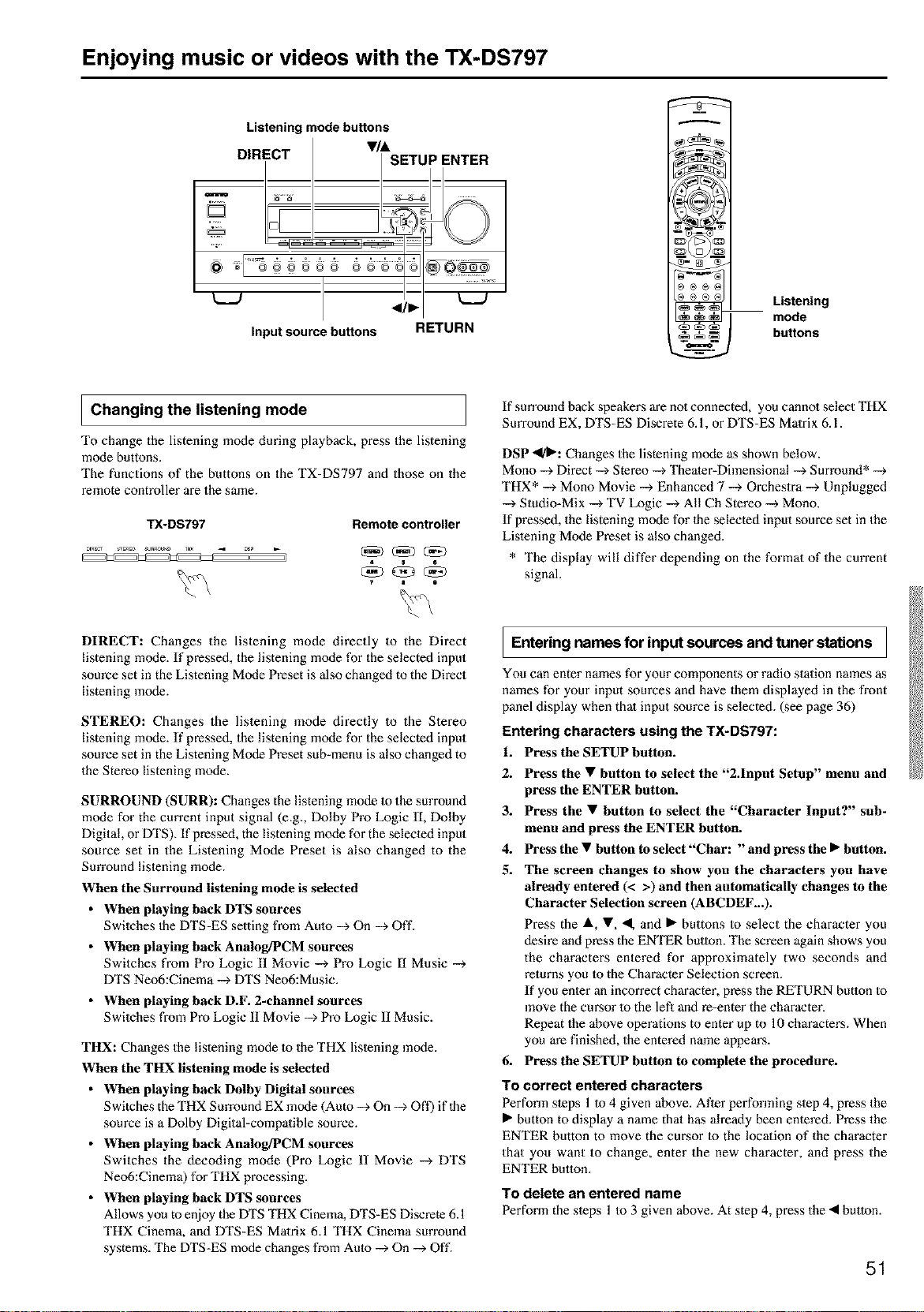
Enjoying music or videos with the TX-DS797
Listening mode buttons
DIRECT •/&
SETUP ENTER
@
= _ ¸¸2¸:¸2¸¸
®@@e@® ®@@
</•
input source buttons RETURN
Listening
mode
buttons
I Changing the listening mode
To change the listening mode during playback, press the listening
mode buttons.
The functions of the buttons on the TX-DS797 and those on the
remote controller are the same.
TX-DS797 Remote controller
If sun'ound back speakers are no1connected, you cannol select THX
Surround EX, DTS-ES Discrete 6.1, or DTS-ES Matrix 6.1.
DSP _1_: Changes the listening mode as shown below.
Mono --_Direct -->Stereo -->Theater-Dimensional -_ Surround* --_
THX* --_ Mono Movie --_ Enhanced 7 --> Orcheslra -->Unplugged
--_ Studio-Mix -->TV Logic --> All Ch Stereo -_ Mono.
If pressed, the listening mode for the selected input source set in the
Lislening Mode Preset is also changed.
* The display will differ depending on the format of the current
signal.
DIRECT: Changes the listening mode directly to the Direct
listening mode. If pressed, the listening mode for the selected input
source set in the Listening Mode Preset is also changed to the Direct
listening mode.
STEREO: Changes the listening mode directly to the Stereo
listening mode. If pressed, the listening mode for the selected input
source set in the Listening Mode Preset sub-menu is also changed to
the Stereo listening mode.
SURROUND (SURR): Changes the listening mode to the surround
mode for the current input signal (e.g. Dolby Pro Logic ll, Dolby
Digital, or DTS). If pressed, the listening mode for the selected input
source set in the Listening Mode Preset is also changed to the
Surround listening mode.
When the Surround listening mode is selected
• When playing back DTS sources
Swilches 1he DTS-ES setting from Aulo --_On --_ Off.
• When playing back Analog/PCM sources
Switches from Pro Logic II Movie --> Pro Logic lI Music --_
DTS Neo6:Cinema -->DTS Neo6:Music.
• When playing back D.F. 2-channel sources
Swilches from Pro Logic II Movie --_ Pro Logic II Music.
THX: Changes the listening mode to the THX lislening mode.
When the THX listening mode is selected
• When playing back Dolby Digital sources
Switches the THX Surround EX mode (Auto --> On -_ Off) if the
source is a Dolby Digital-compatible source.
• When playing back Analog/PCM sources
Switches the decoding mode (Pro Logic II Movie --_ DTS
Neo6:Cinema) for THX processing.
• When playing back DTS sources
Allows you to enjoy the DTS THX Cinema, DTS-ES Discrete 6.1
THX Cinema, and DTS-ES Matrix 6.1 THX Cinema surround
systems. The DTS-ES mode changes fi'om Aulo --_ On --_ Off.
I Entering names for input sources and tuner stations I
You can enter names for your components or radio station names as
names for your input sources and have them displayed in the front
panel display when thai input source is selected. (see page 36)
Entering characters using the TX-DS797:
1. Press the SETUP button.
2.
3.
4.
5.
Press the • button to select the "2.1nput Setup" menu and
press the ENTER button.
Press the • button to select the "Character Input?" sub-
menu and press the ENTER button.
Press the • button to select "Char: "and press the • button.
The screen changes to show you the characters you have
already entered (< >) and then automatically changes to the
Character Selection screen (ABCDEF...).
Press the &, •, •, and • buttons Io select the character you
desire and press the ENTER butlon. The screen again shows you
the characters entered for approximately two seconds and
returns you _o the Character Selection screen.
If you enler an incorrect character, press the RETURN button to
move the cursor lo the lefl and re-enter the character.
Repeat the above operations to enter up to 10 characters. When
you m'e finished, the entered name appem's.
6. Press the SETUP button to complete the procedure.
To correct entered characters
Perfonn sleps 1 to 4 given above. After perfonning slep 4, press the
• button to display a name that has already been enlered. Press the
ENTER button to move the cursor to the localion of the character
that you want to change, enter the new character, and press the
ENTER button.
To delete an entered name
Perform the sleps 1 to 3 given above. At step 4, press the • button.
51
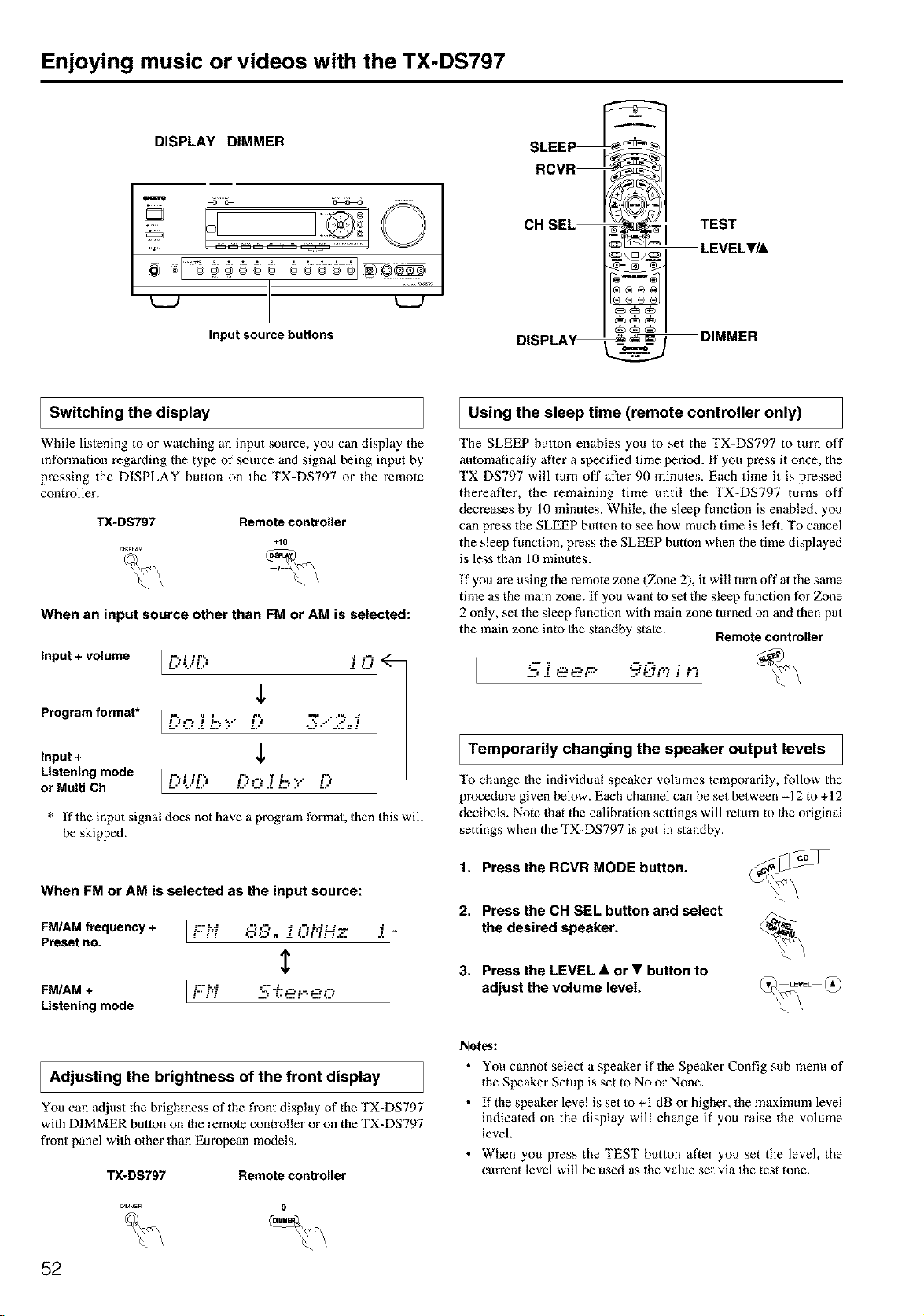
Enjoying music or videos with the TX-DS797
DISPLAY DIMMER
sl s@@ss; 6ssss'@Q:@
Inputsource buttons
I Switching the display
SLEEP
RCVR
CH SEL
DISPLAV
TEST
_ LEVEL•/A
_DIMMER
While listening Io or watching an input source, you can display the
information regarding the type of source and signal being input by
pressing the DISPLAY butlon on the TX-DS797 or the remote
controller.
TX-DS797 Remote controller
+10
_rSPLAY
When an input source other than FM or AM is selected:
Input + volume
Program format*
Input +
Listening mode
or Multi Ch
L.''-..'L.' i i_i
,L
* If the input signal does not have a program format, then this will
be skipped.
When FM or AM is selected as the input source:
FM/AM frequency + L_;:h'_ ,-t_.-, _ ,-,P_L_-_ f
Preset no. ! _ _,:3. _, !.J,','_x.
$
FM/AM + I F-" '---"-......
Listening mode
Using the sleep time (remote controller only)
The SLEEP betlon enables you to set the TX-DS797 to turn off
aulomatically after a specified time period. If you press it once, the
TX-DS797 will turn off after 90 minutes. Each time it is pressed
thereafler, the remaining time until the TX-DS797 turns off
decreases by 10 minutes. While, the sleep function is enabled, you
can press the SLEEP button to see how much time is left. To cancel
the sleep function, press the SLEEP button when the time displayed
is less than 10 minutes.
If you are using the remote zone (Zone 2), it will turn off at the same
time as the main zone. If you want to set the sleep function for Zone
2 only, set the sleep function with main zone turned on and then put
the main zone into the standby state. Remote controller
_. ee r 9 °.;. i '-
Temporarily changing the speaker output levels
To change the individual speaker volumes temporarily, follow the
procedure given below. Each channel can be set between -12 to +12
decibels. Note that the calibration settings will return to the original
settings when the TX-DS797 is put in standby.
1. Press the RCVR MODE button.
2. Press the CH SEL button and select
the desired speaker.
3. Press the LEVEL • or • button to
adjust the volume level.
I Adjusting the of the front
brightness display
You can adjust the brightness of the front display of the TX-DS797
with DIMMER button on the remote controller or on the TX-DS797
front panel wilh other than European models.
TX-DS797 Remote controller
_M_E_ 0
52
Notes:
• You cannot select a speaker if the Speaker Config sub-menu of
the Speaker Setup is set to No or None.
• If the speaker level is set to +1 dB or higher, the maximum level
indicated on the display will change if you raise the volume
level.
• When you press the TEST button after you set the level, the
current level will be used as the value set via the test tone.
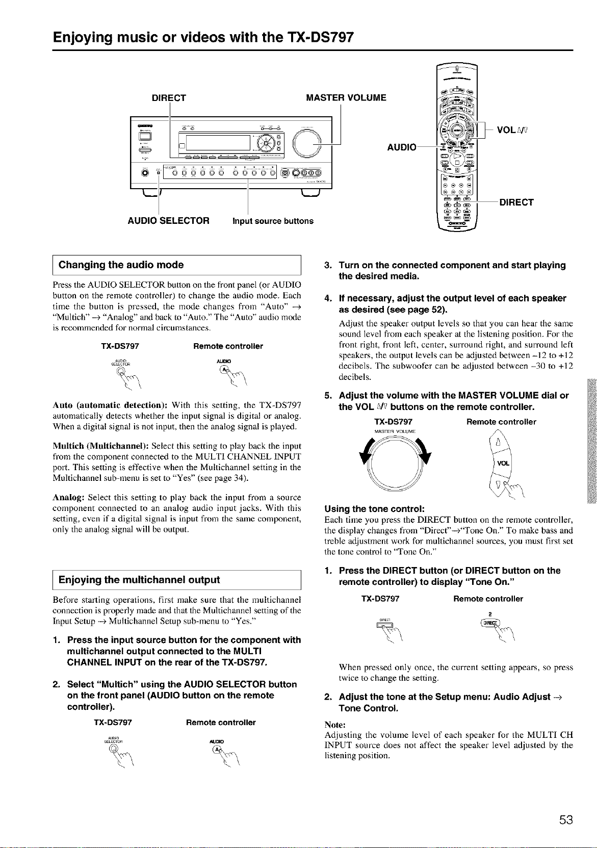
Enjoying music or videos with the TX-DS797
DIRECT MASTER VOLUME
__._/ _'
AUDIO SELECTOR Input source buttons
DIRECT
I Changing the audio mode
Press the AUDIO SELECTOR button on the front panel (or AUDIO
button on the remole controller) to change the audio mode. Each
time the button is pressed, the mode changes from "Auto" --_
"Multich" --> "Analog" and back to "Auto." The "Auto" audio mode
is recommeoded for normal circumstances.
TX-DS797 Remote controller
Auto (automatic detection): With this setting, the TX-DS797
aulomatically delects whether the input signal is digital or analog.
When a digital signal is not input, then the analog signal is played.
Maltich (Maltichannel): Select this setting to play back the input
from the component connected to the MULTI CHANNEL INPUT
port. This se,ing is effective when the Multichannel setting in the
Multichannel sub-menu is set to "Yes" (see page 34).
Analog: Select this setting to play back the input from a source
component connected to an analog audio input jacks. With this
setting, even if a digital signal is input from the same component,
only the analog signal will be output.
I Enjoying the multichannel output
Before starting operations, fix_st make sure that the multichannel
connection is properly made and thai 1he Multichannel setting of the
Input Setup --_ Multichannel Setup sub-menu 1o "Yes."
1. Press the input source button for the component with
multichannel output connected to the MULTI
CHANNEL INPUT on the rear of the TX-DS797.
2. Select "Multich" using the AUDIO SELECTOR button
on the front panel (AUDIO button on the remote
controller).
TX-DS797 Remote controller
AUD_
SELECrC_ AUDIO
3.
4.
5.
Turn on the connected component and start playing
the desired media.
If necessary, adjust the output level of each speaker
as desired (see page 52).
Adjust the speaker oulput levels so that you can hear the same
sound level from each speaker at the lislening position. For the
front right, front lefi, cenler, surround right, and surround left
speakei_s, the oulput levels can be adjusled between -12 to +12
decibels. The subwoofer can be adjusted between -30 to +12
decibels.
Adjust the volume with the MASTER VOLUME dial or
the VOL _/v buttons on the remote controller.
TX-DS797 Remote controller
MASTER VOLUME
Using the tone control:
Each time you press the DIRECT button on the remole controller,
the display changes from "Direct'-->"Tone On." To make bass and
treble adjustment work for multichannel sources, you must first set
the lone control to "Tone On."
1. Press the DIRECT button (or DIRECT button on the
remote controller) to display "Tone On."
TX-DS797 Remote controller
When pressed only once, the current selling appem_s, so press
twice Io change the setting.
2. Adjust the tone at the Setup menu: Audio Adjust -_
Tone Control.
Note:
Adjusting the volume level of each speaker for the MULTI CH
INPUT source does not affect the speaker level adjusted by the
lislening position.
53
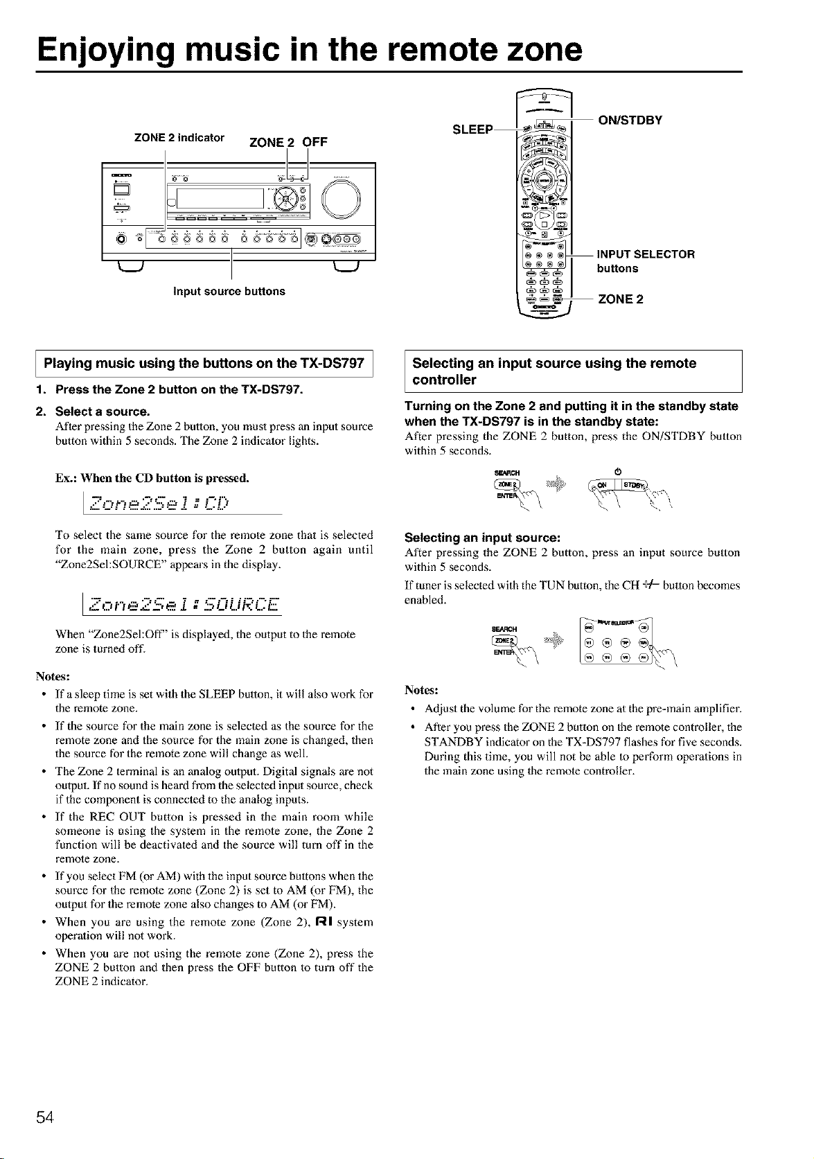
Enjoying music in the remote zone
ZONE 2 indicator ZONE 2 OFF
I 1.....................
t__J t__J
input source buttons
ON/STDBY
buttons
ZONE 2
I Playing music the buttons the TX-DS797 /
]
using
on
1. Press the Zone 2 button on the TX-DS797.
2. Select a source.
After pressing the Zone 2 button, you must press an input source
button within 5 seconds. The Zone 2 indicator lights.
Ex.: When the CD button is pressed.
I =8--::-
To select the same source for the remote zone that is selected
for the main zone, press the Zone 2 button again until
"Zone2SehSOURCE" appears in the display.
l ,._: ....-- .: _ ...-..-... ::-..-.:...
",:5.0 i'3 e.eS--, _' i ;; ".',Li Li i"O.., t::.
When "Zone2Sel:Off" is displayed, the output to the remote
zone is turned oft'.
Notes:
• If a sleep time is set with the SLEEP button, it will also work for
the remote zone.
• If the source for the main zone is selected as the source for the
remote zone and the source for the main zone is changed, then
the source for the remote zone will change as well.
• The Zone 2 terminal is an analog oulput. Digital signals are not
output. If no sound is heard from the selected input source, check
if the component is connected to the analog inputs.
• If the REC OUT button is pressed in the main room while
someone is using the system in the remole zone, the Zone 2
function will be deactivated and the source will turn off in the
remote zone.
• If you select FM (or AM) with the input source bultons when the
source for the remote zone (Zone 2) is set to AM (or FM), the
output for the remote zone also changes to AM (or FM).
• When you are using the remote zone (Zone 2), RI system
operation will not work.
• When you are not using the remole zone (Zone 2), press the
ZONE 2 button and then press the OFF button to turn off the
ZONE 2 indicator.
Selecting an input source using the remote
controller
Turning on the Zone 2 and putting it in the standby state
when the TX-DS797 is in the standby state:
After pressing the ZONE 2 button, press the ON/STDBY button
within 5 seconds.
s_ac, 0_
Selecting an input source:
After pressing the ZONE 2 button, press an input source button
within 5 seconds.
If tuner is selected with the TUN button, the CH ÷/= button becomes
enabled.
SEARCH
Notes:
• Adjust the volume for the remote zone at the pre=main amplifier.
• After you press the ZONE 2 button on the remote controller, the
STANDBY indicator on the TX-DS797 flashes for five seconds.
During this time, you will not be able to perform operations in
the main zone using the remote controller.
54

Recording a source
REC OUT
1. Press the CD input source button.
2. Set 'WIDEO 5" for the Video setting in the Video Setup sub-
menu of the Setup menu: Input Setup -_ Video Setup -_
Video.
3. Insert a CD in the CD player and insert a tape in the video
camera connected to the VIDEO 5 IN.
4. Insert a video tape for recording in the video cassette
recorder connected to VIDEO 1 OUT.
5. From this step on, follow the same procedure as described in
2 and 3 above.
k__J L__J Notes:
Notes:
Input source buttons
• You cannot record the surround effects.
• Digital signals input to the DIGITAL INPUT (COAX) and
DIGITAL INPUT (OlYl ") inputs will be oulput to the DIGITAL
OUTPUT (OPT) output.
• There are some restrictions on recording digital signals. When
making digital recordings, consult the instruction manual that
came with your digital recording equipment (e.g., MD recorder
or DAT deck) to know what reslrictions are imposed.
• You cannot record the source connected to the MULTI
CHANNEL INPUT connector.
To record the input source signal you are
currently watching or listening to
This method outputs Io the audio and video outputs the currently
selected input source signal. This method allows you to a signal
while you are actually listening Io or watching it.
1. Select the input source to record by pressing the
corresponding input source button.
The input source is now selected and you may watch or lislen to
it as desired.
2. Press the REC OUT button repeatedly until "Rec
SehSOURCE" appears in the front display.
The currently selected input source signal to the TAPE OUT,
t--: ..... :-- .. ? = =--:%':" t."-::"'i--
/_ p.,t , ._-fz:_ J. = _D L.I t_l/_ L.,/Z
VIDEO 1 OUT, VIDEO 2 OUT oulputs for recording.
3. Start recording at the recording component as
desired.
To confirm the settings, press the Rec Out button. The current
settings will appear for 3 seconds in the front display.
Recording the video from one source and the audio from
another:
You can add the sound from one source to the video of another
source to make your own video recordings.
Below is an example of recording the sound from a compact disc
player connected to CD IN and the video from a video camera
connected to VIDEO 5 IN to video cassette tape in a video cassette
recorder connected to the VIDEO 1 OUT jack.
• If you change the input source dining recording, you will record
the signals from the newly selected input source.
• Digital input signals are only output to the digital oulputs and
analog input signals are only output from the analog outputs,
There is no conversion from digital to analog or vice versa.
When connecting CD players and other digital components, do
no1 connect only the digital terminals, but the analog ones as
well.
To record an input source signal different from
that you are currently watching or listening to
This method outputs to the audio and video outputs the signal from
the input source that you select here. This allows you to record an
input source signal different from that which you m'e listening to or
watching at the time of recording.
1. Press the Rec Out button.
2. Within 5 seconds, press the input source selector
button of the input source signal that you wish to
record.
The signal from the selected input source will now be output to
the TAPE OUT, VIDEO 1 OUT, and VIDEO 2 OUT outputs for
recording.
I --:.-...... :---..-. " = i " T 1"=_'t" "-i %:22_,,, _: _ d, = ",." ,L _.-"/.,,, :.,,:"..:
3. Start recording at the recording component as
desired.
To confirm the settings, press the Rec Out bulton. The current
settings will appem" for 5 seconds in the front display.
Notes:
• Be aware that the remote (Zone 2) and recording (REC OUT)
outputs use the same circuit and therefore can be used at the
same time.
• If you select FM (or AM) with the input source bultons when the
recording source is set to AM (or FM), the output for the
recording source also changes to AM (or FM).
55
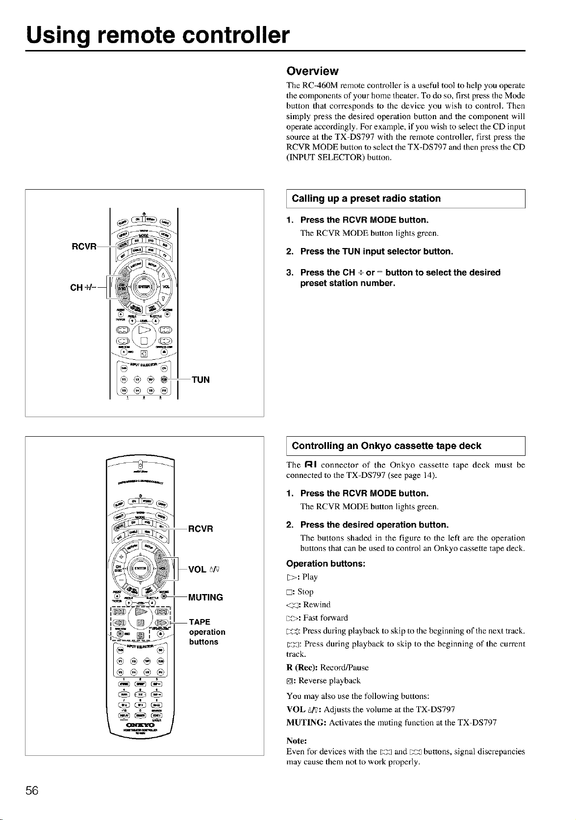
Using remote controller
Overview
The RC=460M remote controller is a useful 1ooi to help you operate
the components of your home theater. "I_ do so, first press the Mode
button that corresponds Io the device you wish to control. Then
simply press the desired operalion button and the component will
operate accordingly. For example, if you wish to select the CD input
source at the TX=DS797 with the remote controller, first press the
RCVR MODE button 1oselect the TX=DS797 and then press the CD
(INPUT SELECTOR) button.
®®®@ TUN
Calling up a preset
radio station
1. Pressthe RCVR MODE button.
The RCVR MODE button lights green.
2. Pressthe TUN input selector button.
3. Press the CH _ or = button to select the desired
preset station number.
RCVR
MUTING
TAPE
operation
buttons
Controlling an Onkyo tape
cassette deck
The RI connector of the Onkyo cassette tape deck must be
connected Io the TX=DS797 (see page 14).
1. Press the RCVR MODE button.
The RCVR MODE button lights green.
2. Press the desired operation button.
The butlons shaded in the figure to the left are the operation
buttons thai can be used Io control an Onkyo cassette tape deck.
Operation buttons:
[_,: Play
[2: Stop
<_: Rewind
[Z>: Fast forward
C:_: Press during playback to skip to the beginning of the next 1rack.
Z_:a:Press during playback Io skip to the beginning of the current
track.
R (Re¢): RecoM/Pause
@: Reve_:se playback
You may also use the following buttons:
VOL _/V: Adjusts the volume at the TX-DS797
MUTING: Activates the muting function at the TX-DS797
Note:
Even for devices with the _ and _ butlons, signal discrepancies
may cause them not Io work properly.
56
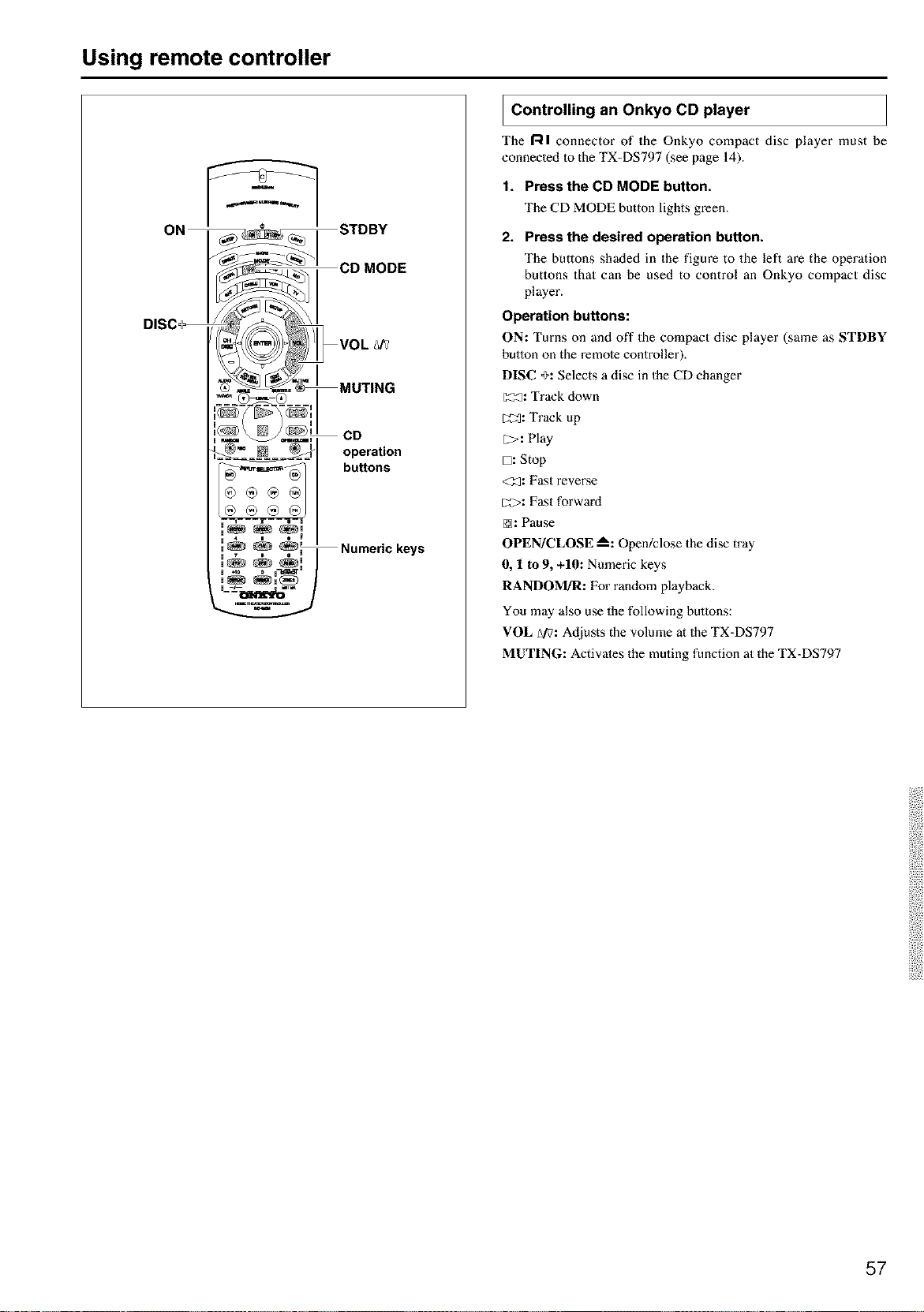
Using remote controller
operation
buttons
U 4 e I
!_ _ _L Numeric keys
u
I Controlling an Onkyo player
CD
The gl connector of the Onkyo compact disc player must be
eonneeled 1othe TX-DS797 (see page 14).
1. Press the CD MODE button.
The CD MODE button lights green.
2. Press the desired operation button.
The buttons shaded in the figure to the left are the operation
buttons that can be used to control an Onkyo compact disc
player.
Operation buttons:
ON: Turns on anti off the compact disc player (same as STDBY
button on the remote controller).
DISC _: Selects a disc in the CD changer
[_: Track down
_3: Track up
l>: Play
D: Stop
<_: Fast revense
c2>: Fast forward
@: Pause
OPEN/CLOSE m_:Open/close the disc tray
0, 1 to 9, +10: Numeric keys
RANDOM!R: For random playback.
You may also use the following buttons:
VOL Ai?:Adjusts the volume at the TX-DS797
MUTING: Activates the muting function at the TX-DS797
57
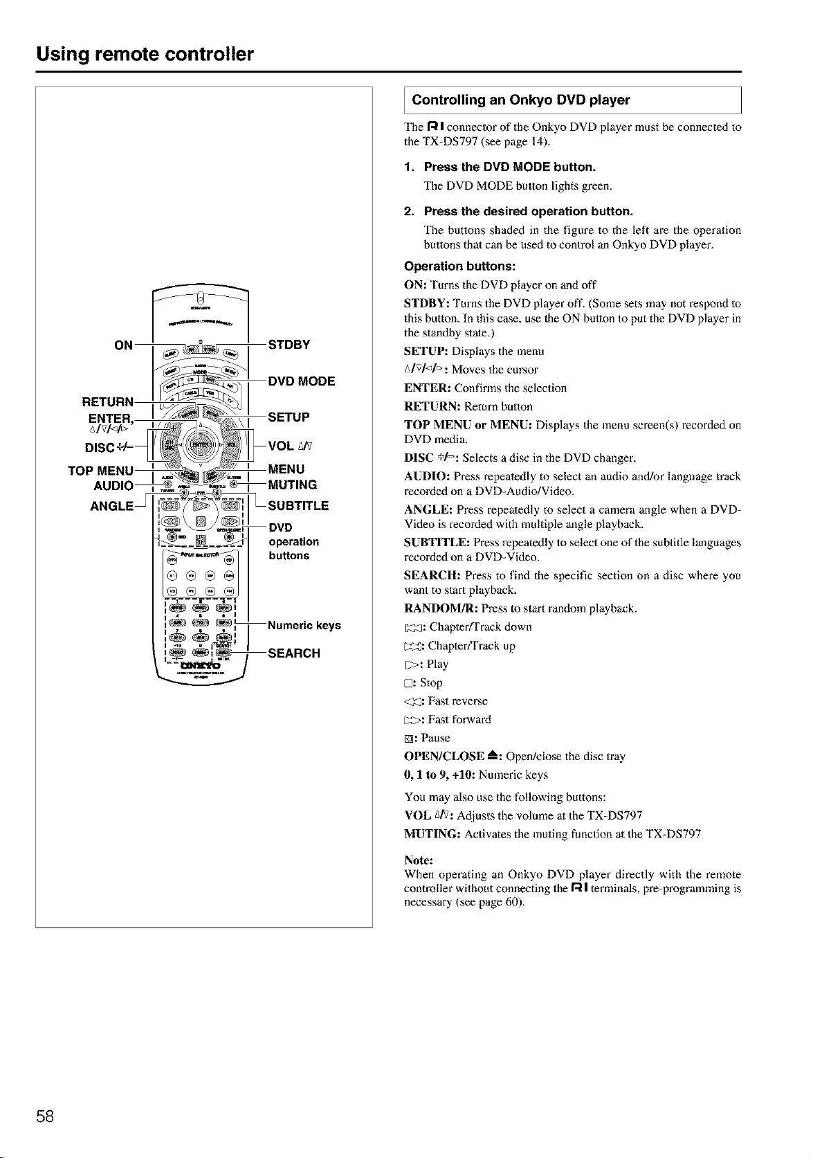
Using remote controller
operation
buttons
Numeric keys
SEARCH
Controlling an Onkyo player
DVD
The R I conneoor of the Oakyo DVD player must be conneoed to
the TX-DS797 (see page 14).
1. Press the DVD MODE button.
The DVD MODE button lights green.
2. Press the desired operation button.
The butlons shaded in the figure to the left are the operation
buttons that can be used to control an Onkyo DVD player.
Operation buttons:
ON: Turns the DVD player on and oft"
STDBY: Turns the DVD player off. (Some sets may not respond 1o
this button. In this case, use 1he ON button Io put the DVD player in
the standby state.)
SETUP: Displays the menu
A/V/</_: Moves the cursor
ENTER: Confirms the selection
RETURN: Return button
TOP MENU or MENU: Displays the menu screen(s) recorded on
DVD media.
DISC +¢=: Selects a disc in the DVD changer.
AUDIO: Press repealedly to select an audio and!or language track
recorded on a DVD=Audio/Video.
ANGLE: Press repeatedly to select a camera angle when a DVD-
Video is recorded with multiple angle playback.
SUBTITLE: Press repeatedly Io select one of the subtitle languages
recorded on a DVD=Video.
SEARCH: Press to find the specific section on a disc where you
want to start playback.
RANDOM/R: Press to start random playback.
[1:_: Chapter/Track down
[_0: Chapter/Track up
[2>: Play
C2:Stop
<_: Fast reverse
[;2>: Fast forward
@: Pause
OPEN/CLOSE ---_:Opediclose the disc tray
0, 1 to 9, +10: Nmneric keys
You may also use the following buttons:
VOL _iV: Adjusts the volume at the TX=DS797
MUTING: Activates the muting function at the TX-DS797
Note:
When operating an Onkyo DVD player directly with the remote
controller without connecting the I-4 | terminals, pre=programming is
necessary (see page 60).
58
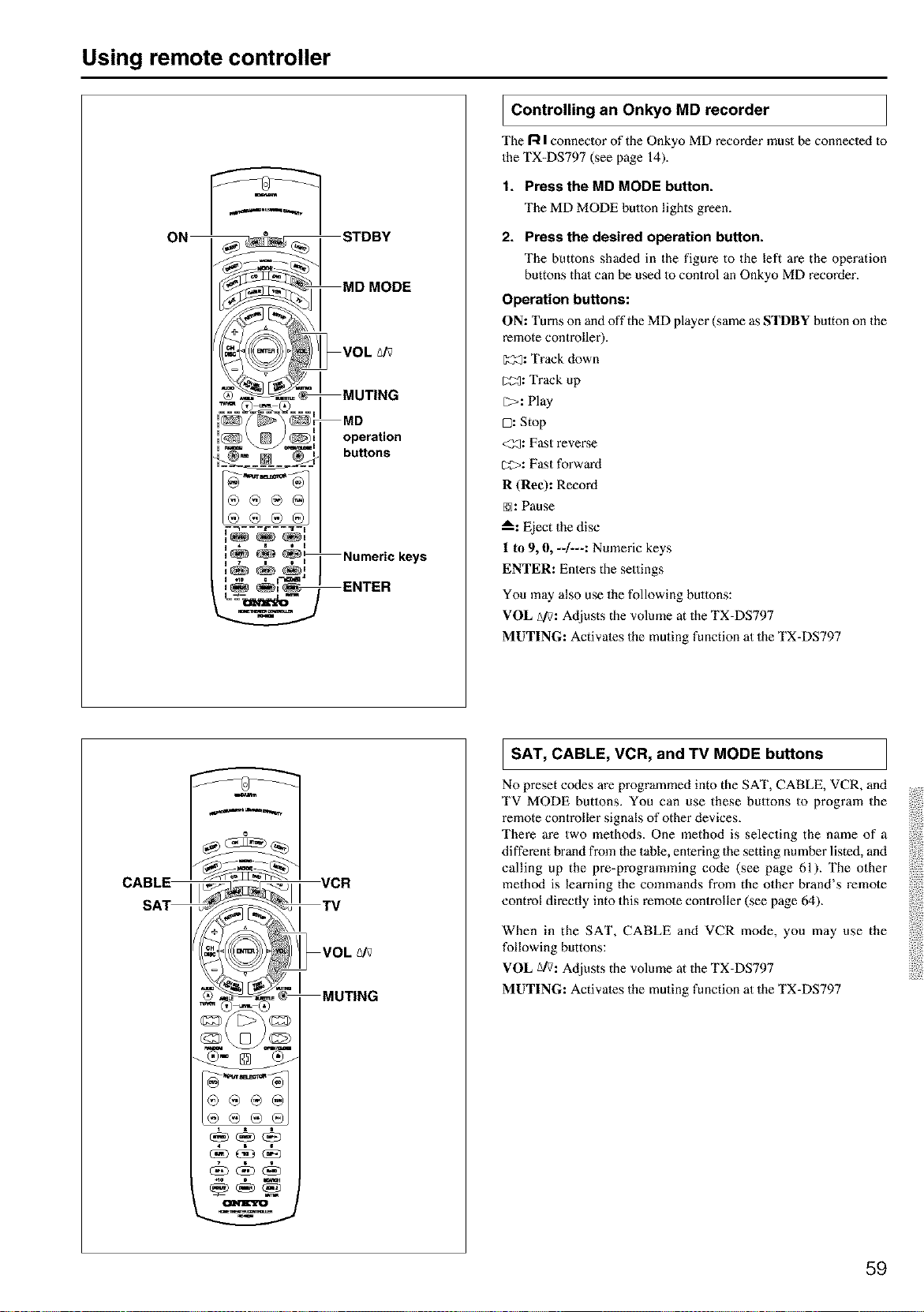
Using remote controller
I Controlling an Onkyo
MD recorder
The R Iconneclor of the Onkyo MD recorder must be connected to
the TX-DS797 (see page 14).
1. Press the MD MODE button.
The MD MODE button lights green.
2. Press the desired operation button.
The buttons shaded in the figure to the left are the operation
buttons thai can be used to control an Onkyo MD recorder.
Operation buttons:
ON: Turns on anti off the MD player (same as STDBY bulton on the
remote controller).
[Z_: Track down
_2_: Track up
E;>: Play
H _ s t H
H 7 i e H
a n0 =
L _-_1_1_ m
mwm
MD
operation
buttons
Numeric keys
ENTER
D: Stop
<33: Fast revez:se
CO>: Fast forward
R (Ree): Record
@: Pause
A: Eject the disc
1 to 9, 0, --/---: Numeric keys
ENTER: Entez:s the settings
You may also use the following buttons:
VOL Ai?: Adjusts the volume at the TX-DS797
MUTING: Activates the muting function at the TX-DS797
CABL_
SA_
I SAT, CABLE, VCR, and TV MODE buttons
No preset codes are programmed into the SAT, CABLE, VCR, and
TV MODE buttons. You can use these buttons to program the
remote controller signals of other devices.
There are two methods. One method is selecting the name of a
different brand from the table, entering the setting number listed, and
calling up the pre-programming code (see page 61). The other
method is learning the commands from the other brand's remote
control directly into this remote controller (see page 64).
When in the SAT, CABLE and VCR mode, you may use the
following buttons:
VOL Ai?: Adjusts the volume at the TX-DS797
MUTING: Activates the muting function at the TX-DS797
59
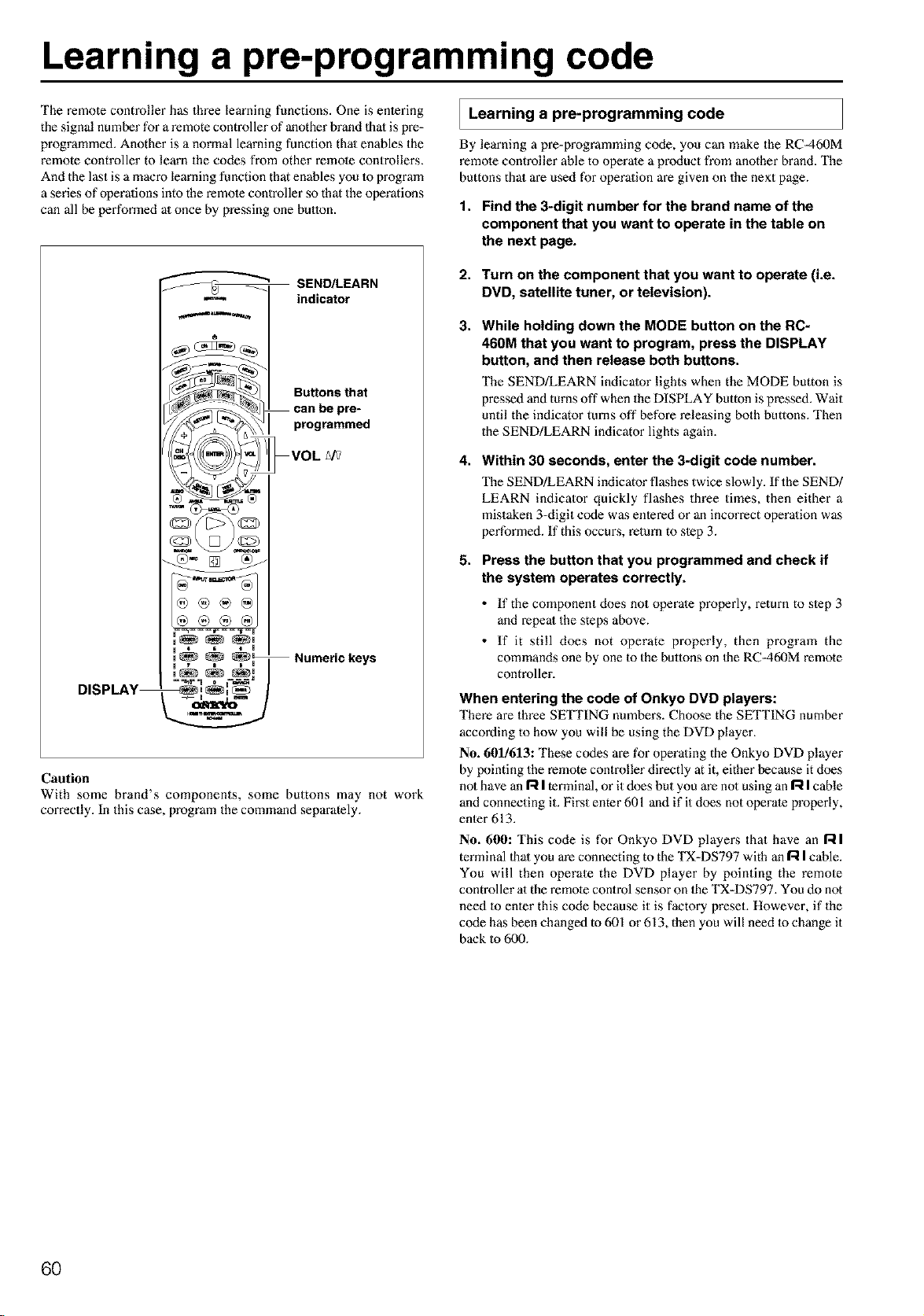
Learning a pre-programming code
The remote controller has three learning functions. One is enlering
the signal number for a remote controller of another brand 1halis pre-
programmed. Another is a normal learning function thai enables the
remote controller to learn the codes from other remote contrNlers.
And the last is a macro learning function that enables you 1oprogram
a series of operalions into the remote controller so that the operations
can all be performed al once by pressing one button.
Learning a pre-programming code
By learning a pre=programming code, you can make the RC=460M
remote controller able to operate a product from another brand. The
buttons thai are used for operalion are given on the next page.
1. Find the 3-digit number for the brand name of the
component that you want to operate in the table on
the next page.
SEND/LEARN
m indicator
Caution
With some brand's components, some buttons may not work
correctly. In this case, program the command separately.
2. Turn on the component that you want to operate (i.e.
DVD, satellite tuner, or television).
3,
While holding down the MODE button on the RC-
460M that you want to program, press the DISPLAY
button, and then release both buttons.
The SEND/LEARN indicator lights when the MODE button is
pressed and turns off when the DISPLAY button is pressed. Wait
until the indicator turns off before releasing both buttons. Then
the SEND!LEARN indicator lights again.
4,
Within 30 seconds, enter the 3-digit code number.
The SEND/LEARN indicator flashes twice slowly. If the SEND/
LEARN indicator quickly flashes three times, then either a
mistaken 3-digit code was entered or an incorrect operalion was
performed. If this occux_s, return to slep 3.
5,
Press the button that you programmed and check if
the system operates correctly.
• If the component does not operate properly, return to slep 3
and repeal the steps above.
• If it still does not operate properly, then program the
commands one by one 1othe buttons on 1he RC=460M remote
controller.
When entering the code of Onkyo DVD players:
There are three SETTING numbers. Choose the SETTING number
according to how you will be using the DVD player.
No. 601/613: These codes are for operating the Onkyo DVD player
by pointing the remote controller directly at it, either because it does
not have an R I terminal, or it does but you are no1using an I"-tIcable
and connecting it. First emer 601 and if it does not operate properly,
enler 613.
No. 600: This code is for Onkyo DVD playei_s that have an I--II
terminal 1hal you are connecting to the TX-DS797 with an [--iIcable.
You will then operate the DVD player by pointing the remote
controller al the remote control sensor on 1he TX-DS797. You do not
need 1o enler this code because it is factory preset. However, if the
code has been changed to 601 or 613, then you will need to change it
back to 600.
6O
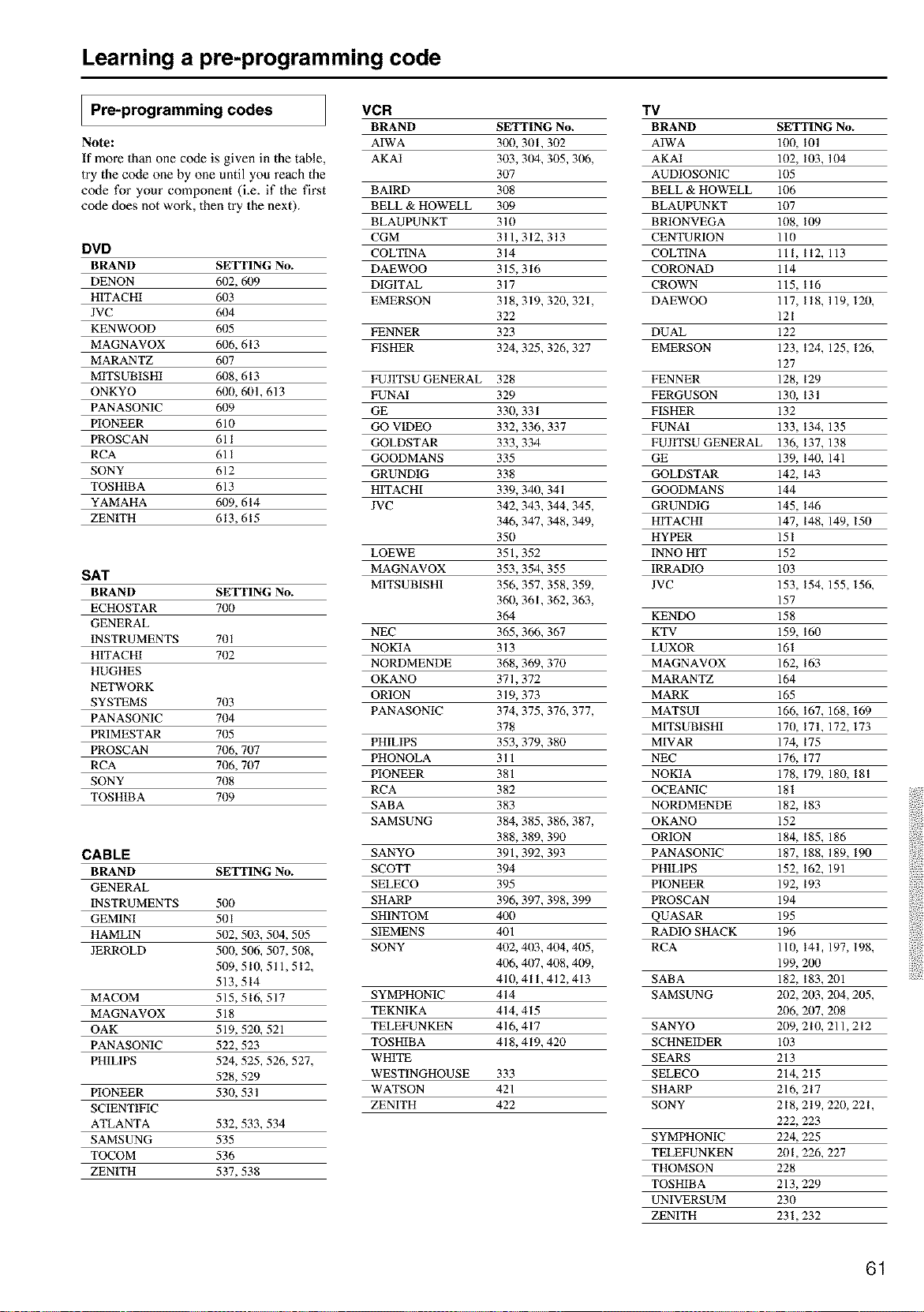
Learning a pre-programming code
Pre-programming codes VCR TV
BRAND SETTING No. BRAND SETTING No.
Note: AIWA 300, 301,302 AIWA 100, 101
If more than one code is given in the table, AKAI 303, 3(14, 305, 306, AKAI 102, 103, 104
try the code one by one until you reach the 307 AUDIOSONIC 105
code for your component (i.e. if the first BAIRD 308 BELL & HOWELL 106
code does not work, then try the next). BELL & HOWELL 309 BLAUPUNKT 107
BLAUPUNKT 310 BRIONVEGA 108, 109
CGM 311, 312, 313 CENTURION 110
DVD COLTINA 314 COLTINA 111, 112, 113
BRAND SETTING No. DAEWOO 315, 316 CORONAD 114
DENON 6(12, 609 DIGITAL 317 CROWN 115, 116
HITACHI 6(13 EMERSON 318, 319, 320, 321, DAEWOO 117, 118, 119, 120,
JVC 6()4 322 121
KENWOOD 6(15 FENNER 323 DUAL 122
MAGNAVOX 6()6, 613 FISHER 324, 325,326, 327 EMERSON 123, 124, 125, 126,
MARANTZ 6(17 127
MITSUBISHI 6()8,613 FUJITSU GENERAL 328 FENNER 128, 129
ONKYO 6(10, 601, 613 FUNAI 329 FERGUSON 130, 13I
PANASONIC 6(19 GE 330, 331 FISHER 132
PIONEER 610 GO VIDEO 332, 336,337 FUNAI 133, 134, 135
PROSCAN 611 GOLDSTAR 333, 334 FUJITSU GENERAL 136, 137, 138
RCA 611 GOODMANS 335 GE 139, 140, 141
SONY 612 GRUNDIG 338 GOLDSTAR 142, 143
TOSHIBA 613 HITACHI 339, 340, 341 GOODMANS 144
YAMAHA 6(19, 614 JVC 342, 343,344, 345, GRUNDIG 145, 146
ZENITH 613, 615 346, 347,348, 349, HITACHI 147, 148, 149, 150
350 HYPER 151
LOEWE 351,352 INNO HIT 152
SAT MAGNAVOX 353, 354, 355 IRRADIO 103
M1TSUBISH1 356, 357,358, 359, JVC 153, 154, 155, 156,
BRAND SETTING No.
3611, 361,362, 363, 157
ECHOSTAR 700
364 KENDO 158
GENERAL
NEC 365, 366, 367 KTV 159, 160
INSTRUMENTS 701
NOKIA 313 LUXOR 161
HITACHI 702
NORDMENDE 368, 369, 370 MAGNAVOX 162, 163
HUGHES
OKANO 371,372 MARANTZ 164
NETWORK
ORION 319, 373 MARK 165
SYSTEMS 703
PANASONIC 374, 375,376, 377, MATSUI 166, 167, 168, 169
PANASONIC 704
378 MITSUBISHI 170, 171, 172, 173
PRIMESTAR 705
PHILIPS 353, 379, 380 MIVAR 174, 175
PROSCAN 706, 707
PHONOLA 311 NEC 176, 177
RCA 706, 707
PIONEER 381 NOKIA 178, 179, 180, 181
SONY 708
RCA 382 OCEANIC 181
TOSHIBA 709
SABA 383 NORDMENDE 182, 183
SAMSUNG 384, 385,386, 387, OKANO 152
388, 389, 390 ORION 184, 185, 186
CABLE SANYO 391,392, 393 PANASONIC 187, 188, 189, 190
BRAND SETTING No. SCOTI" 394 PH1L1PS 152, 162, 191
GENERAL SELECO 395 PIONEER 192, 193
INSTRUMENTS 500 SHARP 396, 397,398, 399 PROSCAN 194
GEMINI 501 SHINTOM 40!1 QUASAR 195
HAMLIN 502, 503, 504, 505 SIEMENS 401 RADIO SHACK 196
JERROLD 500, 506, 507,508, SONY 402, 403,404, 405, RCA 110, 141, 197, 198,
509, 510, 511,512, 406, 4t/7,408, 409, 199, 200
513,514 410,411,412,413 SABA 182, 183,201
MACOM 515,516, 517 SYMPHONIC 414 SAMSUNG 202, 203, 204, 205,
MAGNAVOX 518 TEKNIKA 414, 415 206, 207, 208
OAK 519, 520, 521 TELEFUNKEN 416, 417 SANYO 209, 210, 211,212
PANASONIC 522, 523 TOSHIBA 418, 419, 420 SCHNEIDER 103
PHILIPS 524, 525, 526, 527, WHITE SEARS 213
528,529 WESTINGHOUSE 333 SELECO 214,215
PIONEER 530, 531 WATSON 421 SHARP 216, 217
SCIENTIFIC ZENITH 422 SONY 218, 219, 220, 221,
ATLANTA 532, 533, 534 222, 223
SAMSUNG 535 SYMPHONIC 224, 225
TOCOM 536 TELEFUNKEN 201,226, 227
ZENITH 537,538 THOMSON 228
TOSHIBA 213,229
UNIVERSUM 230
ZENITH 231,232
61
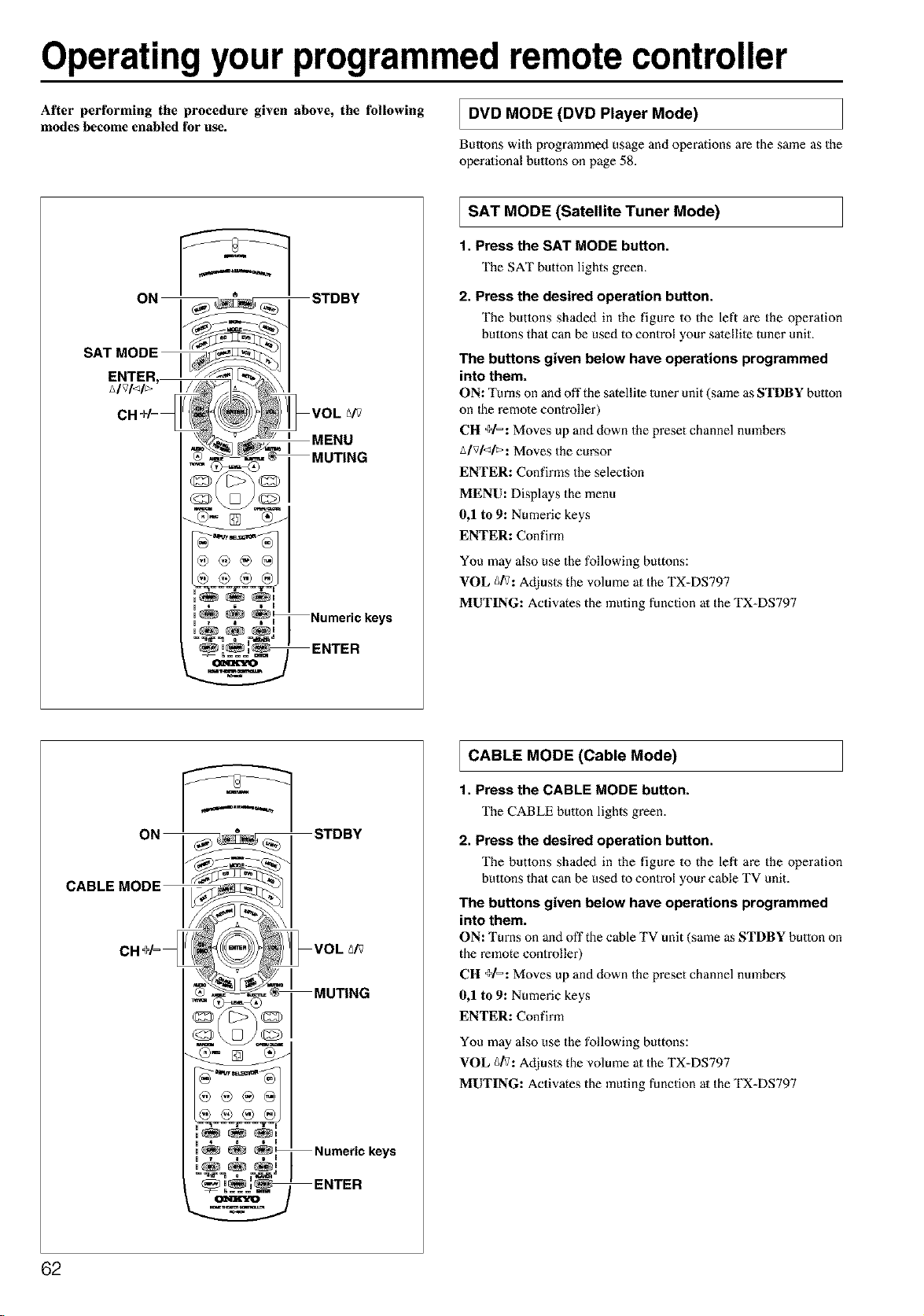
Operatingyour programmedremote controller
After performing the procedure given above, the following
modes become enabled for use.
DVD (DVD Player Mode)
MODE
Buttons with programmed usage and operations are the same as the
operational buttons on page 58.
_, u Numeric keys
SAT (Satellite Mode)
MODE Tuner
1. Press the SAT MODE button.
The SAT button lights green.
2. Press the desired operation button.
The buttons shaded in the figure to the left are the operation
buttons that can be used to control your sate[lile tuner unit.
The buttons given below have operations programmed
into them.
ON: Turns on and off the satellite tuner unit (same as STDBY button
on 1he remote controller)
CH +1=: Moves up and down the preset channel numbers
A/vl<l_: Moves the cursor
ENTER: Confirms the selection
MENU: Displays the menu
0,1 to 9: Numeric keys
ENTER: Confirm
You may also use the following buttons:
VOL g/V: Adjusts the volume at the TX-DS797
MUTING: Activates the muting function at the TX-DS797
u 4 i I
u_ _, , u Numeric keys
ENTER
CABLE (Cable Mode)
MODE
1. Press the CABLE MODE button.
The CABLE button lights green.
2. Press the desired operation button.
The buttons shaded in the figure to the left are the operation
buttons that can be used to control your cable TV unit.
The buttons given below have operations programmed
into them.
ON: Turns on anti off the cable TV unit (same as STDBY button on
the remote controller)
CH +1=: Moves up and down the preset channel nmnbers
0,1 to 9: Numeric keys
ENTER: Confirm
You may also use the following buttons:
VOL _/V: Adjusts the volume at the TX-DS797
MUTING: Activates the muting function at the TX-DS797
62
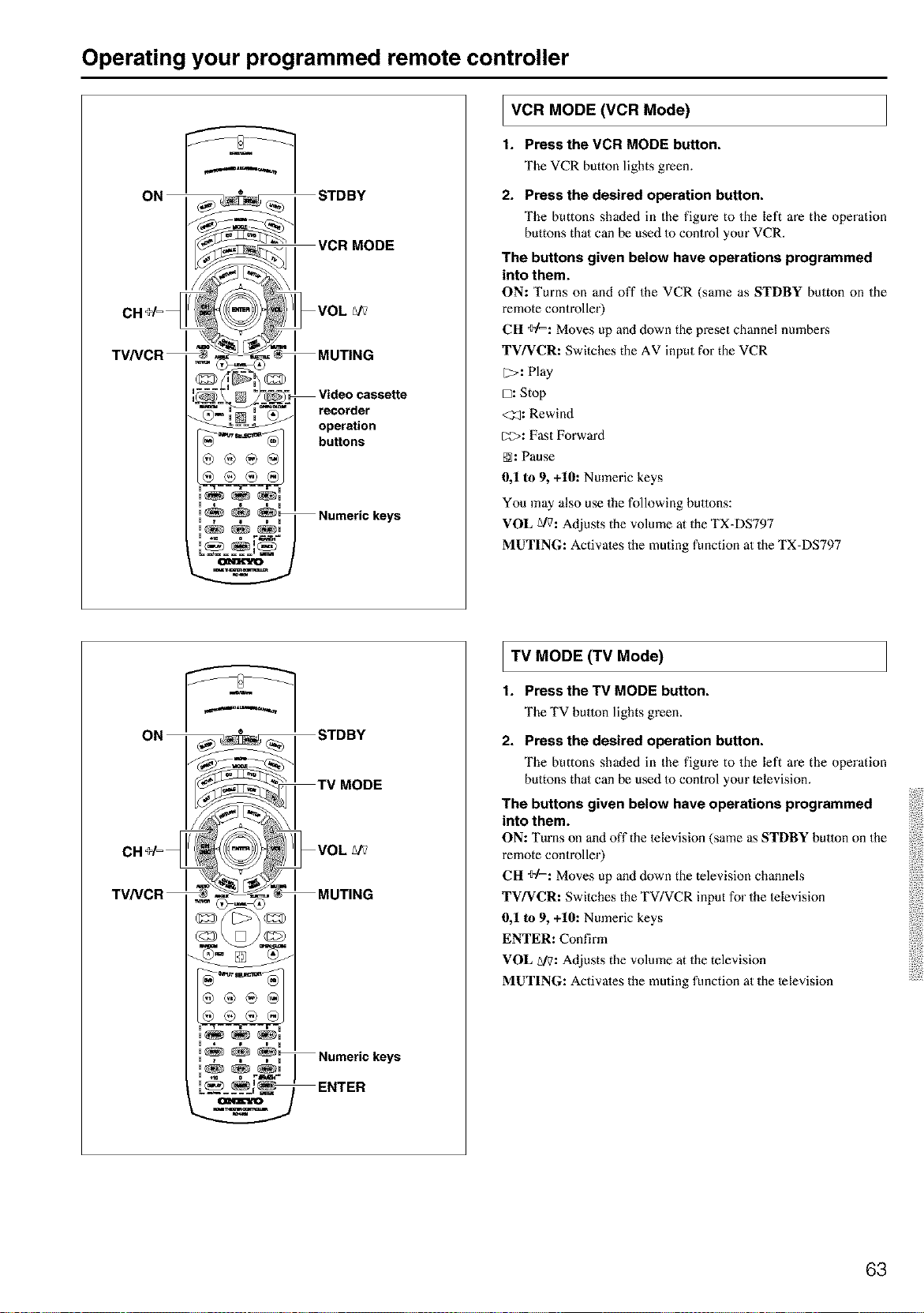
Operating your programmed remote controller
u 4 6 i u
, 7 i D u
_==_==__
operation
buttons
Numeric keys
I VCR (VCR Mode)
MODE
t. Pressthe VCR MODE button.
The VCR button lights green.
2. Press the desired operation button.
The buttons shaded in the figure to the left are the operation
buttons thai can be used Io control your VCR.
The buttons given below have operations programmed
into them.
ON: Turns on and off the VCR (same as STDBY button on the
remote controller)
CH ÷1=: Moves up and down the preset channel numbers
TV/VCR: Switches the AV input for the VCR
[2>: Play
D: Stop
<_: Rewind
_>: Fast Forward
@: Pause
0,1 to 9, +10: Numeric keys
You may also use the following buttons:
VOL g/7: Adjusts the volume at the TX=DS797
MUTING: Activates the muting function at the TX=DS797
u • i i u
,_ _ _
, . . . , Numeric keys
u _t= o Fm*_ ="
.... ENTER
TV (TV Mode)
MODE
1. Press the TV MODE button,
The TV button lights green.
2. Press the desired operation button.
The buttons shaded in the figure to the left are the operation
buttons thai can be used Io control your lelevision.
The buttons given below have operations programmed
into them.
ON: Turns on and off the lelevision (same as STDBY button on the
remote controller)
CH ÷1=: Moves up and down the television channels
TV/VCR: Switches the TV/VCR input for the lelevision
0,1 to 9, +10: Numeric keys
ENTER: Confirm
VOL A/7: Adjusts the volume at the television
MUTING: Activates the muting function at the television
63
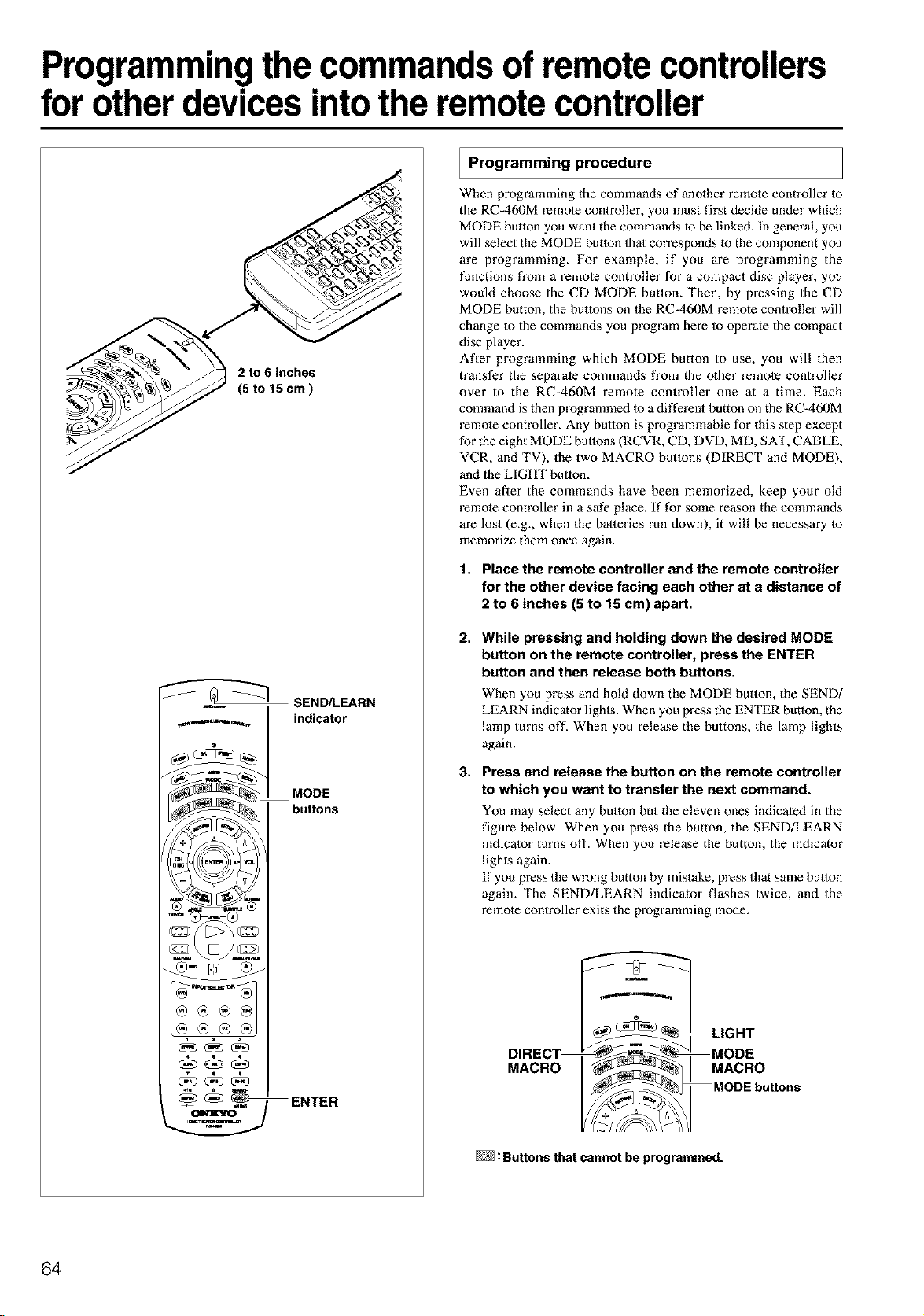
Programmingthe commands of remote controllers
for other devices intothe remote controller
2 to 6 inches
(5 to 15cm)
SEND/LEARN
ENTER
Programming procedure
When programming the commands of anolher remole controller 1o
the RC-460M remote conlroller, you must first decide under which
MODE button you want the commands to be linked. In general, you
will select the MODE button 1halcorresponds 1othe component you
are programming. For example, if you are programming the
functions from a remota controller for a compact disc player, you
would choose the CD MODE butlon. Then, by pressing the CD
MODE button, the buttons on the RC-460M remote controller will
change Io the commands you program here Io operate the compact
disc player.
After programming which MODE button to use, you will then
transfer the separate commands from the o_her remole controller
over to the RC=460M remote controller one at a time. Each
command is then programmed 1oa different button on the RC=460M
remote controller. Any button is programmable for this step except
for the eight MODE buttons (RCVR, CD, DVD, MD, SAT, CABLE,
VCR, and TV), the two MACRO butlons (DIRECT and MODE),
and the LIGHT button.
Even aBer the commands have been memorized, keep your old
remote controller in a safe place. If for some reason the commands
are lost (e.g., when the batteries run down), it will be necessary Io
memorize them once again.
1. Place the remote controller and the remote controller
for the other device facing each other at a distance of
2 to 6 inches (5 to 15 cm) apart.
2.
3.
While pressing and holding down the desired MODE
button on the remote controller, press the ENTER
button and then release both buttons.
When you press and hold down the MODE btalota the SEND/
LEARN indicator lighls. When you press the ENTER button, the
lamp turns oft'. When you release the buttons, the lamp lights
again.
Press and release the button on the remote controller
to which you want to transfer the next command.
You may select any button but the eleven ones indicaled in the
figure below. When you press the button, the SEND/LEARN
indicalor turns off. When you release the button, the indicator
lighls again.
If you press the wrong button by mistake, press that same button
again. The SEND!LEARN indicator flashes twice, and the
remole controller exits the programming mode.
DIRECT
MACRO
m
LIGHT
MODE
MACRO
MODEbu_ons
: Buttons that cannot be programmed.
64
Programming the commands of remote controllers for other devices into the
remote controller
4. Press and hold down the button (that corresponds to
the command you are programming) on the remote
controller of the other device until the SEND/LEARN
lamp on the remote controller flashes twice.
After flashing twice, the SEND/LEARN indicator will light
again.
5. Repeat Steps 3 and 4 to transfer all the commands
you desire from the other remote controller and
program them to buttons on the remote controller
under the same MODE.
Repeat Steps 2 through 4 to program commands Io a different
MODE (e.g., when programming fi'om a different remote
controller).
6. Press the MODE button that you pressed in step 2 to
complete the programming.
7. Operatethe newly programmed buttons to make sure
the learning function was performed properly.
Notes:
• The remote controller codes for Onkyo compact disc players,
cassette tape decks, DVD playel_s, and mini disc recorder have
already been programmed into buttons on the remote controller.
You may, however, use these buttons to program the codes for
olher remote controllers. If you wish to restore the Onkyo preset
codes after you program new codes, you must first erase the new
codes (see page 66).
• The remote controller has 408 memory slots (8 modes x 51
bulmns). Some remote controllers may have more commands
thai can be remembered by the remote controller. In such cases,
it will be necessary for you to determine which commands are
more important than othe_zs.
• If no butlon is pressed for more than 30 seconds dm'ing the
programming, or if you perform an invalid operation during
programming, the SEND!LEARN indicator flashes three times
quickly, and the remote controller exits the programming mode.
Resume fi'om Step 2.
• If a failure occurs dm'ing programming, the SEND!LEARN
indicator flashes three times quickly, and the remote controller
exits the programming mode. Resume from Step 3.
• If a failure occurs five times in row during programming, the
remote controller exits the programming mode. Resume from
Step 3.
• If you try to program beyond the learning capacity of the remote
controller, the SEND/LEARN indicator flashes six times
quickly, and the remote controller exits the programming mode.
Try programming under a different MODE button.
• When you want to program a command to a button to which you
have already programmed a command, simply follow the same
procedure given and programming for that button will be
overwritten.
• The remote controller uses infrared rays to send its commands,
as do most other remote controllers. Though most remote
controller codes can be memorized by the remote controller, be
aware that some remote controllers use a system that is quite
different from the remote controller and therefore may not be
able to be programmed.
• Some remote controllers have a single button that performs
multiple functions (for example, the function may change each
time the button is pressed)_ If this is the case, each function must
be programmed to a separate button on the remote controller.
• Once you have transferred the commands from the other remote
controller, refer to the instruction manual that came with that
product for instructions on how to operate that product.
• Make sure both the remote controller and the other remote
controller have new batteries. If either of them has balteries that
are low, you may not be able to program the commands of the
other remote controller properly into the remote controller.
See page 70 for how to erase the memorized commands from all
buttons.
65
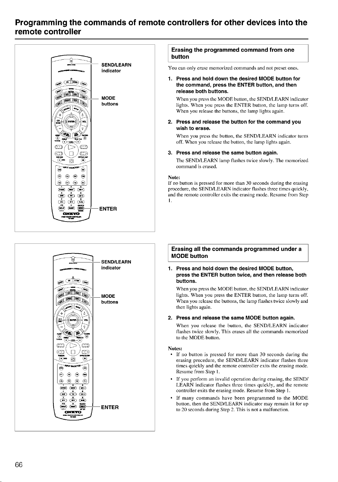
Programming the commands of remote controllers for other devices into the
remote controller
SEND/LEARN
indicator
MODE
bu_ons
ENTER
Erasing the programmed command from one
button
You can only erase memorized commands and not preset ones.
1. Press and hold down the desired MODE button for
the command, press the ENTER button, and then
release both buttons.
When you press the MODE button, the SEND/LEARN indicator
lights. When you press the ENTER button, the lamp turns oft'.
When you release the buttons, the lamp lights again.
2.
Press and release the button for the command you
wish to erase.
When you press the button, the SEND/LEARN indicator turns
off. When you release the button, the lamp lights again.
3. Press and release the same button again.
The SEND/LEARN lamp flashes twice slowly. The memorizod
command is erased.
Note:
If no button is pressed for more than 30 seconds during the erasing
procedure, the SEND/LEARN indicator flashes three times quickly,
and the remote controller exits the erasing mode. Resmne from Step
1.
SEND/LEARN
,,,.,.,._,_,...,_ indicator
MODE
buttons
ENTER
Erasing all the commands programmed under a
MODE button
1. Press and hold down the desired MODE button,
press the ENTER button twice, and then release both
buttons.
2.
When you press the MODE button, the SEND!LEARN indicator
lights. When you press the ENTER button, the lamp turns off.
When you release the buttons, the lamp flashes twice slowly and
then lights again.
Press and release the same MODE button again.
When you release the button, the SEND/LEARN indicator
flashes twice slowly. This erases all the commands memorized
Io the MODE button.
Notes:
• If no button is pressed for more than 30 seconds during the
erasing procedure, the SEND!LEARN indicator flashes three
times quickly and the remote controller exits the erasing mode.
Resume from Step 1.
• If you perform an invalid operation during erasing, the SEND/
LEARN indicator flashes three times quickly, and the remote
controller exits 1he erasing mode. Resume from Step 1.
• If many commands have been programmed to the MODE
button, then the SEND!LEARN indicator may remain lit for up
to 20 seconds during Step 2. This is not a malfunction.
66
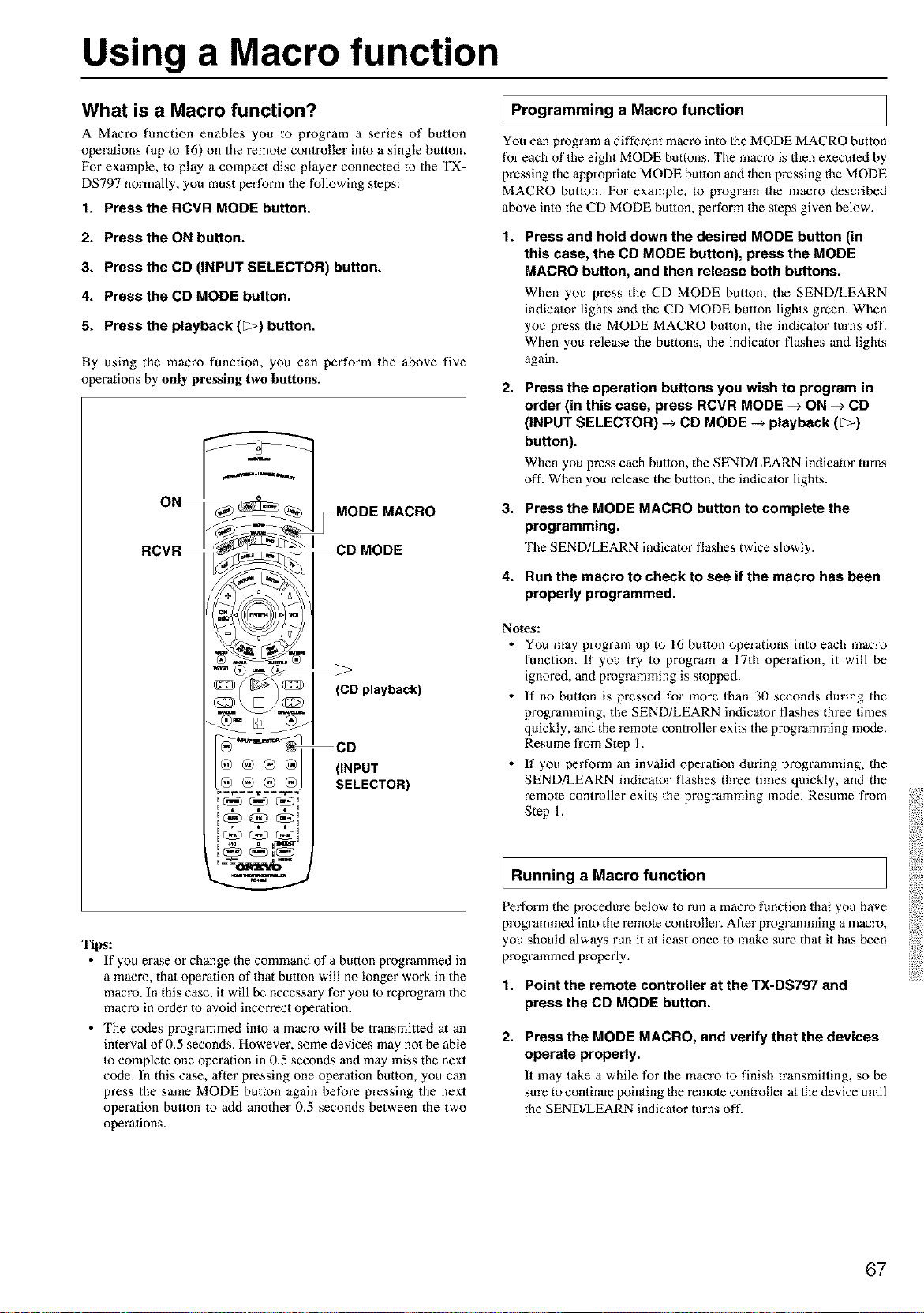
Using a Macro function
What is a Macro function?
A Macro function enables you to program a series of button
operations (up 1o 16) on the remote controller into a single button.
For example, to play a compact disc player connected to the TX-
DS797 normally, you must perform the following steps:
1. Press the RCVR MODE button.
2. Press the ON button.
3. Press the CD (INPUT SELECTOR) button.
4. Press the CD MODE button.
5. Press the playback (_) button.
By using the macro function, you can perform the above five
operations by only pressing two buttons.
RCVR _j I CD MODE
[3>
(CD playback)
®@®81 CD
(iNPUT
SELECTOR)
, H
+10 0
H H
Tips:
• If you erase or change the command of a button programmed in
a macro, that operation of that button will no longer work in the
macro. In this case it will be necessary for you Io reprogram the
macro in order to avoid incorrect operation.
• The codes programmed into a macro will be transmitted at an
interval of 0.5 seconds. However, some devices may no1be able
Io complete one operation in 0.5 seconds and may miss the next
ccxte. In this case, after pressing one operalion button, you can
press the same MODE button again before pressing the next
operation button to add another 0.5 seconds between the two
operations.
I Programming a Macro function
You can program a different macro into 1he MODE MACRO button
for each of the eight MODE buttons. The macro is then execuled by
pressing the appropriate MODE button and then pressing the MODE
MACRO button. For example, to program the macro described
above into the CD MODE button, perform the steps given below.
t.
Press and hold down the desired MODE button (in
this case, the CD MODE button), press the MODE
MACRO button, and then release both buttons.
When you press the CD MODE button, the SEND/LEARN
indicator lights and the CD MODE bulmn lights green. When
you press the MODE MACRO button, the indicator turns off.
When you release the buttons, the indicator flashes and lights
again.
2.
Press the operation buttons you wish to program in
order (in this case, press RCVR MODE -> ON -_ CD
(INPUT SELECTOR) -> CD MODE -> playback ([>)
button).
When you press each button, the SEND/LEARN indicator turns
off. When you release the button, the indicator lights.
3. Press the MODE MACRO button to complete the
programming.
The SEND/LEARN indicator flashes twice slowly.
4. Run the macro to check to see if the macro has been
properly programmed.
Notes:
• You may program up to 16 bulton operations into each macro
function. If you try to program a 17th operation, it will be
ignored, and programming is slopped.
• If no butlon is pressed for more than 30 seconds during the
programming, the SEND/LEARN indicator flashes three times
quickly, and the remote controller exits the programming mode.
Resmne from Step 1.
• If you perform an invalid operation during programming, the
SEND/LEARN indicator flashes three times quickly, and the
remote controller exits the programming mode. Resume from
Step 1.
I Running a Macro function
Perform the procedure below to run a macro function that you have
programmed into the remote controller. After programming a macro,
you should always run it at least once to make sure that it has been
programmed properly.
1. Point the remote controller at the TX-DS797 and
press the CD MODE button.
2. Press the MODE MACRO, and verify that the devices
operate properly.
It may take a while for the macro to finish transmitting, so be
sure to continue pointing the remote controller at the device until
the SEND!LEARN indicator turns off.
67
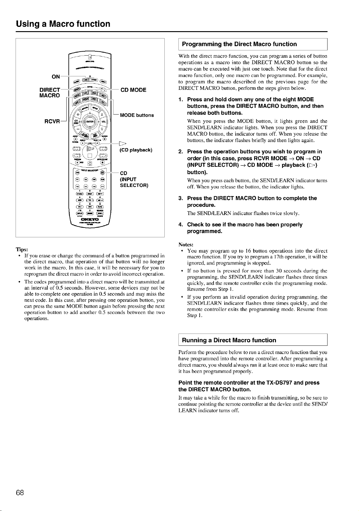
Using a Macro function
ON
DIRECT
MACRO
RCVR
CD MODE
MODE buttons
(CD playback)
(INPUT
SELECTOR)
Tips:
• If you erase or change the command of a button programmed in
the direct macro, that operation of that button will no longer
work in the macro. In this case, it will be necessary for you to
reprogram the direct macro inorder to avoid incorrect operation.
• The codes programmed into a direct macro will be transmitted at
an inlerval of 0.5 seconds. However, some devices may not be
able to complete one operalion in 0.5 seconds and may miss the
next code. In this case, after pressing one operalion button, you
can press the same MODE button again before pressing the next
operation button to add another 0.5 seconds between the two
operalions.
Programming the Direct Macro function
With the direct macro function, you can program a series of button
operations as a macro into the DIRECT MACRO butlon so the
macro can be executed with just one 1ouch. Nole that for the direct
macro function, only one macro can be programmed. For example,
to program the macro described on the previous page for the
DIRECT MACRO button, perform the steps given below.
1,
Press and hold down any one of the eight MODE
buttons, press the DIRECT MACRO button, and then
release both buttons.
When you press the MODE button, it lights green and the
SEND/LEARN indicator lights. When you press the DIRECT
MACRO button, the indicator turns off. When you release the
buttons, the indicator flashes briefly and then lights again.
2,
Press the operation buttons you wish to program in
order (in this case, press RCVR MODE -_ ON -_ CD
(INPUT SELECTOR) -_ CD MODE -_ playback (_)
button).
When you press each button, the SEND/LEARN indicator turns
off. When you release the button, the indicator lights.
3. Press the DIRECT MACRO button to complete the
procedure.
The SEND/LEARN indicator flashes twice slowly.
4. Check to see if the macro has been properly
programmed.
Notes:
• You may program up to 16 butlon operations into the direct
macro function. If you try to program a 17th operation, it will be
ignored, and programming is stopped.
• If no button is pressed for more than 30 seconds during the
programming, the SEND/LEARN indicator flashes three times
quickly, and the remote controller exits the programming mode.
Resume from Step 1.
• If you perform an invalid operation during programming, the
SEND/LEARN indicator flashes three times quickly, and the
remote controller exits the programming mode. Resmne from
Step 1.
Running a Direct Macro function
Perform the procedure below to run a direct macro function that you
have programmed inlo the remote controller. After programming a
direct macro, you should always run it al least once to make sure that
it has been programmed properly.
Point the remote controller at the TX-DS797 and press
the DIRECT MACRO button.
It may take a while for the macro to finish lransmitting, so be sure to
continue pointing the remote controller at 1he device until the SEND/
LEARN indicator turns off.
68
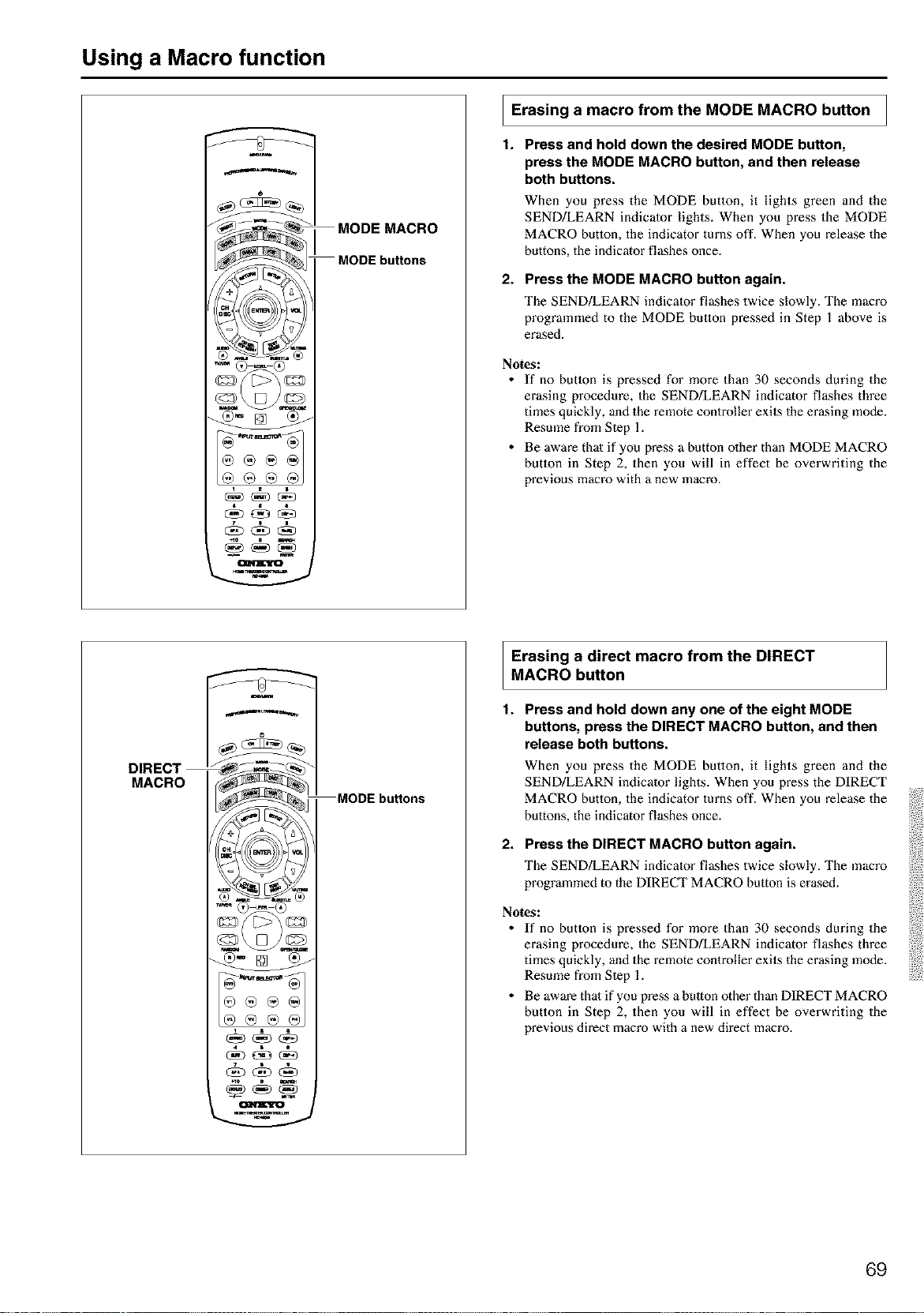
Using a Macro function
MODE MACRO
MODE buttons
n
I Erasing a macro from the MODE MACRO button I
1. Press and hold down the desired MODE button,
press the MODE MACRO button, and then release
both buttons.
When you press the MODE button, it lights green and the
SEND/LEARN indicator lights. When you press the MODE
MACRO button, the indicator turns off. When you release the
buttons, the indicator flashes once.
2. Press the MODE MACRO button again.
The SEND/LEARN indicator flashes twice slowly. The macro
programmed to the MODE button pressed in Step 1 above is
erased.
Notes:
• If no butlon is pressed for more than 30 seconds during the
erasing procedure, the SEND!LEARN indicator flashes three
times quickly, and the remote controller exits the erasing mode.
Resmne from Slep 1.
• Be aware thai if you press a button olher than MODE MACRO
button in Step 2, then you will in effect be overwriting the
previous macro with a new macro.
DIRECT
MACRO
u
®®@
MODE buttons
Erasing a direct macro from the DIRECT
MACRO button
1.
Press and hold down any one of the eight MODE
buttons, press the DIRECT MACRO button, and then
release both buttons.
When you press the MODE button, it lights green and the
SEND/LEARN indicator lights. When you press the DIRECT
MACRO button, the indicator turns off. When you release the
buttons, the indicator flashes once.
2. Press the DIRECT MACRO button again.
The SEND/LEARN indicator flashes twice slowly. The macro
programmed to the DIRECT MACRO button is erased.
Notes:
• If no butlon is pressed for more than 30 seconds during the
erasing procedure, the SEND!LEARN indicator flashes three
times quickly, and the remote controller exits the erasing mode.
Resume from Slep 1.
• Be aware thai if you press a bulton other than DIRECT MACRO
button in Step 2, then you will in effect be overwriting the
previous direct macro with a new direct macro.
69
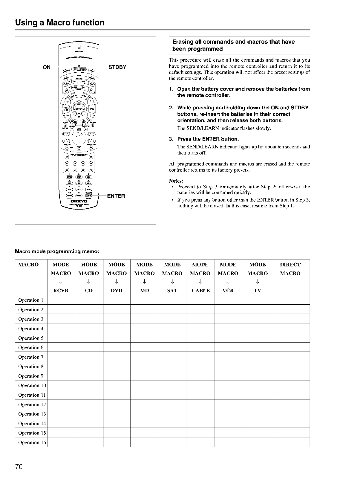
Using a Macro function
STDBY
Erasing all commands and macros that have
been programmed
This procedure will erase all the commands and macros that you
have programmed into the remote controller and return it 1o its
default settings. This operation will not affect the preset settings of
the remote controller.
1,
2.
3,
Open the battery cover and remove the batteries from
the remote controller.
While pressing and holding down the ON and STDBY
buttons, re-insert the batteries in their correct
orientation, and then release both buttons.
The SEND/LEARN indicator flashes slowly.
Press the ENTER button.
The SEND!LEARN indicator lights up for about ten seconds and
then turns off.
_) L',_r 0sta_i_a_
4o ckDc_o
ENTER
All programmed commands and macros are erased and the remote
controller returns to its faclory presets.
Notes:
• Proceed to Step 3 immediately after Slep 2; otherwise, the
batteries will be consumed quickly.
• If you press any button other than the ENTER button in Step 3,
nothing will be erased. In this case, resmne from Slep 1.
Macro mode programming memo:
MACRO MODE MODE MODE MODE MODE MODE MODE MODE DIRECT
MACRO MACRO MACRO MACRO MACRO MACRO MACRO MACRO MACRO
$ $ $ $ ,t ,t $ $
RCYR CD DVD MD SAT CABLE VCR T¥
Operation 1
Operation 2
Operation 3
Operation 4
Operation 5
Operation 6
Operation 7
Operation 8
Operation 9
Operation 10
Operation 11
Operation 12
Operation 13
Operation 14
Operation 15
Operation 16
7O
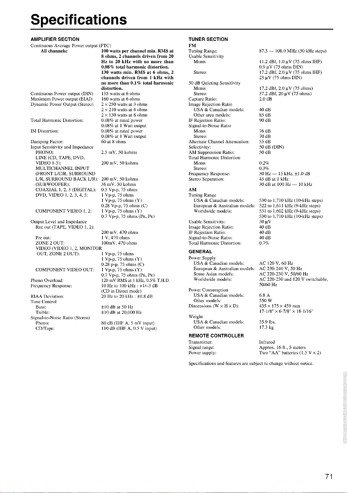
Specifications
AMPLIFIER SECTION
Continuous Average Power output (FTC)
All channels: 100 watts per channel mira RMS at
8 ohms, 2 channels driven from 20
Hz to 20 kHz with no more than
0.08% total harmonic distortion.
130 watts min. RMS at 6 ohms, 2
channels driven from 1 kHz with
no more than 0.1% total harmonic
Continuous Power output (DIN)
Maximum Power output (E1AJ)
Dynamic Power Output (Stereo)
Total Harmonic Distortion:
1M Distortion:
Damping Factor:
Input Sensitivity and Impedance
PHONO:
LINE (CD, TAPE, DVD,
VIDEO 1-5):
MULT1CHANNEL INPUT
(FRONT L/C/R, SURROUND
L/R, SURROUND BACK L/R):
(SUBWOOFER):
COAXIAL 1,2, 3 (DIGITAL):
DVD, VIDEO 1,2, 3, 4, 5:
COMPONENT VIDEO 1, 2:
Output Level and Impedance
Rec out (TAPE, VIDEO 1,2):
TUNER SECTION
FM
Tuning Range:
Usable Sensitivity
Mono:
Stereo:
50 dB Quieting Sensitivity
distortion.
135 watts at 6 ohms
160 watts at 6 ohms
2 x 250 watts at 3 ohms
2 × 210 watts at 4 ohms
2× 130 watts at 8 ohms
0.08% at ra_ed power
0.08% at 1 Watt output
0.08% at rated power
0.08% at 1 Watt output
60 at 8 ohms
2.5 mV, 50 kohms
200 mV, 50 kohms
200 mV, 50 kohms
36 mY, 50 kohms
0.5 Vp-p, 75 ohms
1 Vp-p, 75 ohms
1 Vp-p, 75 ohms (Y)
0.28 Vp-p, 75 ohms (C)
1 Vp-p, 75 ohms (Y)
0.7 Vp-p, 75 ohms (PB, PR)
200 mV, 470 ohms
Pre out: 1 V, 470 ohms
ZONE 2 OUT: 100mV, 470 ohms
VIDEO (VIDEO 1, 2, MONITOR
OUT, ZONE 2 OUT): I Vp-p, 75 ohms
1 Vp-p, 75 ohms (Y)
0.28 p-p, 75 ohms (C)
COMPONENT VIDEO OUT: 1 Vp-p, 75 ohms (Y)
0.7 Vp-p, 75 ohms (PB, PR)
Mono:
Stereo:
Captm-e Ratio:
Image Rejection Ratio
USA & Canadian models:
Other area models:
IF Rejection Ratio:
Signal-to-Noise Ratio
Mono:
Stereo:
Alternate Channel Attenuation:
Selectivity:
AM Suppression Ratio:
Total Harnmnic Distortion
Mono:
Stereo:
Frequency Response:
Stereo Separation:
AM
Tuning Range
USA & Canadian models:
European & Australian models:
Worldwide models:
Usable Sensitivity:
Image Rejection Ratio:
IF Rejection Ratio:
Signal-to-Noise Ratio:
Total Harnmnic Distortion:
GENERAL
Power Supply
USA & Canadian models:
European & Australian models:
Some Asian nmdels:
Phono Overload:
Frequency Response:
R1AA Deviation:
Tone Control
Bass:
Treble:
Signal-m-Noise Ratio (Stereo)
Phono:
CD/Tape:
120 mV RMS at 1 kHz, 0.5% T.H.D.
I0 Hz to 100 kHz : +1/-3 dB
(CD in Direct mode)
20 Hz to 20 kHz : ±0.8 dB
±10dB at 50 Hz
±10 dB at 20,0!)0 Hz
80 dB (IHF A, 5 mV input)
110 dB (IHF A, 0.5 V input)
Worldwide models:
Power Consumption
USA & Canadian models:
Other models:
Dimensions (W × H x D):
87.5 -- 108.0 MHz (50 kHz steps)
I 1.2 dBL 1.0 pV (75 ohms IHF)
0.9 pV (75 ohms DIN)
17.2 dBf, 2.0 BV (75 ohms IHF)
23 gV (75 ohms DIN)
17.2 dBL 2.0 gV (75 ohms)
37.2 dBL 20 gV (75 ohms)
2.0 dB
40 dB
85 dB
90 dB
76 dB
70 dB
55 dB
50 dB (DIN)
50 dB
0.2%
0.3%
30 Hz ---- 15 kHz, ±1.0 dB
45dBatlkHz
30dB at 100Hz -- 10 kHz
530 to 1,7 I0 kHz (10-kHz steps)
522 to 1,611 kHz (9-kHz steps)
531 to 1,602 kHz (9-kHz steps)
530 m 1,7 I0 kHz ( 10-kHz steps)
3o_v"
40 dB
40 dB
40 dB
0.7%
AC 120 V, 00 Hz
AC 230-240 V, 50 Hz
AC 220-230 V, 50/60 Hz
AC 220-230 and 120 V switchable,
50/60 Hz
6.8A
550W
435 x 175 x 459mm
17-1/8"x 6-7/8"x 18-1/16"
Weight
USA & Canadian models: 35.9 Ibs.
Other models: 17.3 kg
REMOTE CONTROLLER
Transmitter: Infrared
Signal range: Approx. 16 fl, 5 meters
Power supply: Two "AA" batteries (1.5 V x 2)
Specifications and l_atures are subject to change without notice.
71
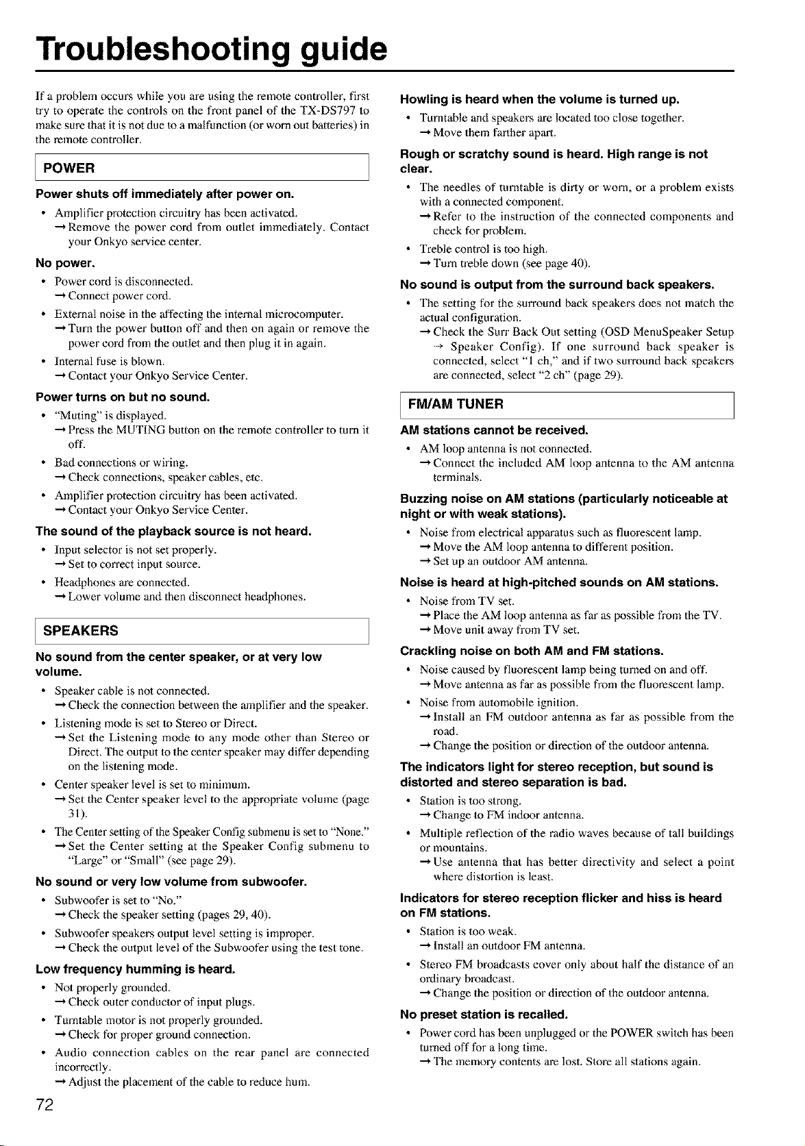
Troubleshooting guide
If a problem occurs while you are using the remote controller, first
try to operale the controls on the front panel of the TX=DS797 Io
make sure that it is not due Io a malfunction (or worn out batteries) in
the remote controller.
POWER
Power shuts off immediately after power on.
• Amplifier protection circuitry has been activated.
-"*Remove the power cord from outlet immedialely. Contact
your Onkyo service center.
NO power.
• Power cord is disconnecled.
-'* Connect power cord.
• External noise in the affecting the internal microoomputer.
-"*Turn the power button off and then on again or remove the
power cord from the outlet and then plug it in again.
• Internal fuse is blown.
-'* Contact your Onkyo Service Cenler.
Power turns on but no sound.
• "Muting" is displayed.
-'* Press the MUTING button on the remote controller to turn it
oft'.
• Bad connections or wiring.
-"*Check connections, speaker cables, ete.
• Amplifier protection circuitry has been activated.
-'* Contact your Onkyo Service Center.
The sound of the playback source is not heard.
• Input selector is not set properly.
-'* Set to correct input source.
• Headphones are connected.
-"*Lower volume and then disconnect heaflphones.
SPEAKERS
No sound from the center speaker, or at very low
volume.
• Speaker cable is no1 connected.
--* Check the connection between the amplifier and the speaker.
• Listening mode is set 1o Stereo or Direct.
--* Set the Listening mode to any mode other than Stereo or
Direct. The output 1o the center speaker may differ depending
on the listening mode.
• Center speaker level is set 1o minimum.
--* Set the Center speaker level to the appropriate volume (page
31).
• Tbe Center setdng of 1heSpeaker Config submenu is set to "None?'
-'* Set the Center setting at the Speaker Config submenu to
"Large" or "Small" (see page 29).
No sound or very low volume from subwoofer.
• Subwoofer is setto "No."
-'* Check the speaker setting (pages 29, 40).
• Subwoofer speakers oulpet level setting is improper.
--* Check the oulput level of the Subwoofer using the test tone.
Low frequency humming is heard.
• Not properly grounded.
-"* Check outer conductor of input plugs.
• Turntable motor is no1 properly grouoded.
-"* Check for proper ground connection.
• Audio connection cables on the rear panel are connected
inoorrectly.
-"* Adjust the placement of the cable 1o reduce hmn.
72
Howling is heard when the volume is turned up.
• Turntable and speakers are located 1oo close together.
--* Move them farther apart.
Rough or scratchy sound is heard. High range is not
clear.
• The needles of turntable is dirty or worn, or a problem exists
with a connected component.
--* Refer to the instruction of the connected components and
check for problem.
• Treble control is too high.
--* Turn treble down (see page 40).
No sound is output from the surround back speakers.
• The setting for the surround back speakers does not mateh the
actual configuration.
--* Check the Sun" Back Out setting (OSD MenuSpeaker Setup
Speaker Config). If one surround back speaker is
connected, select "1 ch," and if two surround back speakers
are connected, select "2 ch" (page 29).
FM/AM TUNER
AM stations cannot bereceived.
• AM loop antenna is no1 connected.
--* Connect the included AM loop antenna to the AM antenna
terminals.
Buzzing noise on AM stations (particularly noticeable at
night or with weak stations).
• Noise from electrical apparatus such as fluorescent lamp.
--* Move the AM loop antenna to different position.
--* Set up an outdoor AM antenna.
Noise is heard at high-pitched sounds on AM stations.
• Noise from TV set.
-"* Place the AM loop antenna as far as possible fi'om the TV.
-"* Move unit away from TV set.
Crackling noise on both AM and FM stations.
• Noise caused by fluorescent lamp being turned on and off.
--* Move antenna as far as possible from the fluorescent lamp.
• Noise from aulomobile ignition.
--* Install an FM outdoor antenna as far as possible from the
road.
--* Change the position or direction of the outdoor antenna.
The indicators light for stereo reception, but sound is
distorted and stereo separation is bad.
• Station is too strong.
--* Change to FM indoor antenna.
• Multiple reflection of the radio waves because of tall buildings
or mountains.
--* Use antenna that has better directivity and select a point
where distortion is least.
Indicators for stereo reception flicker and hiss is heard
on FM stations.
• Station is 1oo weak.
--*Install an outdoor FM antenna.
• Stereo FM broadcasts cover only about half the distance of an
ordinary broadcast.
--* Change the position or direction of the ouldoor antenna.
No preset station is recalled.
• Power cord has been unplugged or the POWER switeh has been
turned off for a long time.
--*The memory contents are lost. Slore all stations again.
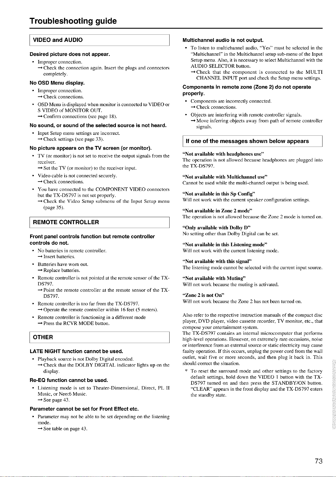
Troubleshooting guide
I VIDEO and AUDIO
Desired picture does not appear.
• Improper connection.
-"*Check the connection again. Insert the plugs and connectons
completely.
No OSD Menu display.
• Improper connection.
-"*Check connections.
• OSD Menu is displayed when monitor is connected to VIDEO or
S VIDEO of MONITOR OUT.
-"*Confirm connections (see page 18).
No sound, or sound of the selected source is not heard.
• Input Setup menu settings are incorrect.
•"* Check settings (see page 33).
No picture appears on the TV screen (or monitor).
• TV (or monitor) is not set Io receive the output signals from the
receiver.
-"*Set the TV (or monitor) to the receiver input.
• Video cable is not connected seem'ely.
-"*Check connections.
• You have connected to the COMPONENT VIDEO connectons
hut the TX-DS797 is not set properly.
-"*Check the Video Setup submenu of the Input Setup menu
(page 35).
IREMOTECONTROLLER
Front panel controls function but remote controller
controls do not.
• No batteries in remote controller.
•"* Insert batteries.
• Batteries have worn out.
-"*Replace batteries.
• Remote controller is not pointed at the remote sensor of the TX-
DS797.
-"*Point the remote controller at the remote sensor of the TX-
DS797.
• Remote controller is too far from the TX-DS797.
-"*Operate the remote controller within 16 feet (5 metens).
• Remote controller is functioning in a different mode
-"*Press the RCVR MODE button.
I OTHER
LATE NIGHT function cannot be used.
• Playback source is not Dolby Digital encoded.
-"*Check that the DOLBY DIGITAL indicator lights up on the
display.
Re-EQ function cannot be used.
• Listening mode is set to Theater-Dimensional, Direct, PL II
Music, or Neo:6 Music.
-"*See page 43.
Parameter cannot be set for Front Effect etc.
• Parameter may not be able Io be set depending on the listening
m_xte,
--*See table on page 43.
Multichannel audio is not output.
• To listen to multichannel audio, "Yes" must be selected in the
"Multichannel" in the Multichannel setup sub=menu of the Input
Setup menu. Also, it is necessary Io select Multichannel with the
AUDIO SELECTOR button.
-"+Check that the component is connected to the MULTI
CHANNEL INPUT port and check the Setup menu seuings.
Components in remote zone (Zone 2) do not operate
properly.
• Components are incorrectly connected.
-"+Check connections.
• Objects are interfering with remote controller signals.
-"+Move inferring objects away from path of remote controller
signals.
If one of the messages shown below appears
"Not available with headphones use"
The operation is not allowed because headphones are plugged into
the TX-DS797.
"Not available with Multiehannel use"
Cannot be used while the multi-channel output is being used.
"Not available in this Sp Config"
Will not work wilh the cm-rent speaker configuration settings.
"Not available in Zone 2 mode"
The operation is not allowed because the Zone 2 mode is turned on.
"Only available with Dolby D"
No setting other than Dolby Digital can be set.
"Not available in this Listening mode"
Will not work wilh the cm-rent listening mode.
"Not available with this signal"
The listening mode cannot be selected with the current input source.
"Not available with Muting"
Will not work because the muting is activated.
"Zone 2 is not On"
Will not work because the Zone 2 has not been turned on.
Also refer to the respective instruction manuals of the compact disc
player, DVD player, video cassette recorder, TV monitor, etc., that
compose your entertainment system.
The TX=DS797 contains an internal microcomputer that performs
highdevel operations. However, on extremely rare occasions, noise
or interference from an external source or static electricity may cause
faulty operation. If this occurs, unplug the power cord from the wall
outlet, wait five or more seconds, and then plug it back in. This
should correct the situation.
* To reset the sm'round mode and other settings to the factory
default settings, hold down the VIDEO 1 button with the TX=
DS797 turned on and then press the STANDBY/ON button.
"CLEAR" appeans in the front display and the TX=DS797 enters
the standby state.
73

Memo
74

Memo
75

ONI_YO CORPORATION
Sales & Product Planning Div. : 2-1, Nisshin-cho, Neyagawe-shi, OSAKA 572-8540, JAPAN
Tel: 072-831-8111 Fax: 072-833-5222
ONKYO U.S.A, CORPORATION
18 Park Way, Upper Saddle River, N.J. 07458, U.S.A.
Tel: 201-785-2600 Fax:201-785-2650 http://www.onkyousa.com
ONKYO EUROPE ELECTRONICS GmbH
Industriestrasse 20, 82110 Germering, GERMANY
ONKYO CHINA LIMITED
Units 2102-2107, Metropleza Tower I, 223 Hing Fong Road, Kwai Chung,
N.T., HONG KONG Tel: 852-2429-3118 Fax: 852-2428-9039 http:/h_vww.onkyo.co.jp/
SN 29343204A D0109-2 [_