0
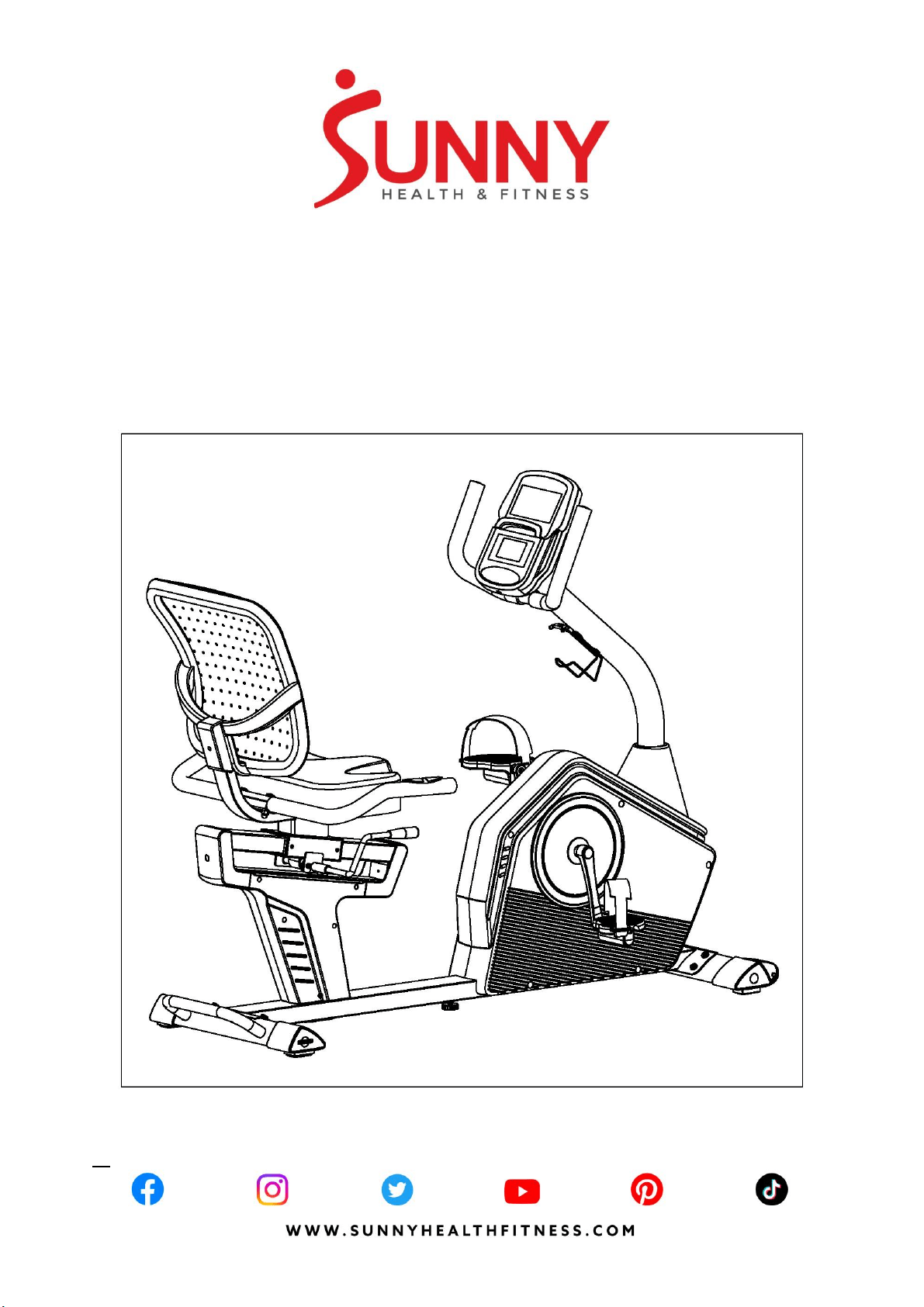
SMART PROGRAMMABLE
RECUMBENT BIKE
SF-RB4850 SMART
USER MANUAL
IMPORTANT! Please retain owner’s manual for maintenance and adjustment instructions. Your
satisfaction is very important to us, PLEASE DO NOT RETURN UNTIL YOU HAVE CONTACTED
US: [email protected] or 1-877-90SUNNY (877-907-8669).

1
IMPORTANT SAFETY INFORMATION
We thank you for choosing our product. To ensure your safety and health, please use this
equipment correctly. It is important to read this entire manual before assembling and using the
equipment. Safe and effective use can only be achieved if the equipment is assembled, maintained,
and used properly. It is your responsibility to ensure that all users of the equipment are informed of
all warnings and precautions.
1. Before starting any exercise program, you should consult your physician to determine if you
have any medical or physical conditions that could put your health and safety at risk or prevent
you from using the equipment properly. Your physician’s advice is essential if you are taking
medication that affects your heart rate, blood pressure, or cholesterol level.
2. Be aware of your body’s signals. Incorrect or excessive exercise can damage your health. Stop
exercising if you experience any of the following symptoms: pain, tightness in your chest,
irregular heartbeat, shortness of breath, lightheadedness, dizziness, or feelings of nausea. If
you do experience any of these conditions, you should consult your physician before continuing
with your exercise program.
3. Keep children and pets away from the equipment. The equipment is designed for adult use only.
4. Use the equipment on a solid, flat level surface with a protective cover for your floor or carpet.
To ensure safety, the equipment should have at least 4 feet (120 CM) of free space all around it.
5. Ensure that all nuts and bolts are securely tightened before using the equipment. The safety of
the equipment can only be maintained if it is regularly examined for damage and/or wear and
tear.
6. Always use the equipment as indicated. If you find any defective components while assembling
or checking the equipment, or if you hear any unusual noises coming from the equipment during
exercise, discontinue use of the equipment immediately and do not use until the problem has
been rectified.
7. Wear suitable clothing while using the equipment. Avoid wearing loose clothing that may
become entangled in the equipment.
8. Do not place fingers or objects into the moving parts of the equipment.
9. The maximum weight capacity of this unit is 300 pounds (135 KG).
10. The equipment is not suitable for therapeutic use.
11. To avoid bodily injury and/or damage to the product or property, proper lifting and moving are
required.
12. Your product is intended for use in cool and dry conditions. You should avoid storage in extreme
cold, hot or damp areas as this may lead to corrosion and other related problems.
13. This equipment is designed for indoor and home use only; it is not intended for commercial use.
2
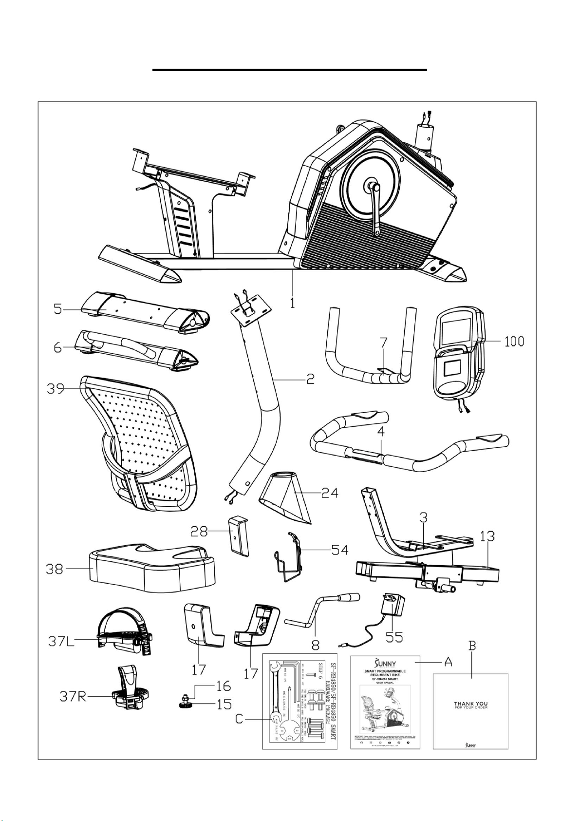
PRE-ASSEMBLY CHECK LIST
.Before you start to assemble, please make sure all parts are included.
3
No.
Description
Spec.
Qty.
No.
Description
Spec.
Qty.
1
Main Frame
1
24
Upright Tube Cover
1
2
Handlebar Post
1
28
Backrest Cover
1
3
Seat Tube
1
37L/R
Pedal
1 pr.
4
Handlebar
1
38
Seat
1
5
Front Stabilizer
1
39
Backrest
1
6
Rear Stabilizer
1
100
Meter
1
7
Armrest
1
54
Bottle Holder
1
8
Adjustment Handle
1
55
Adaptor
1
13
Rail
1
A
Manual
1
15
Adjustable Pad
1
B
Thank You Card
1
16
Hex Nut
M10
1
C
Hardware Package
1
17
Rail Cover
2
4
HARDWARE PACKAGE
Ordering Replacement Parts (U.S. and Canadian Customers only)
Please provide the following information in order for us to accurately identify the part(s) needed:
✓ The model number (found on cover of manual)
✓ The product name (found on cover of manual)
✓ The part number found on the “EXPLODED DIAGRAM” and “PARTS LIST” (found near the front
of the manual)
Please contact us at [email protected] or 1-877-90SUNNY (877-907-8669).
5
ASSEMBLY INSTRUCTIONS
We value your experience using Sunny Health and Fitness products. For assistance with parts or
(877-907-8669).
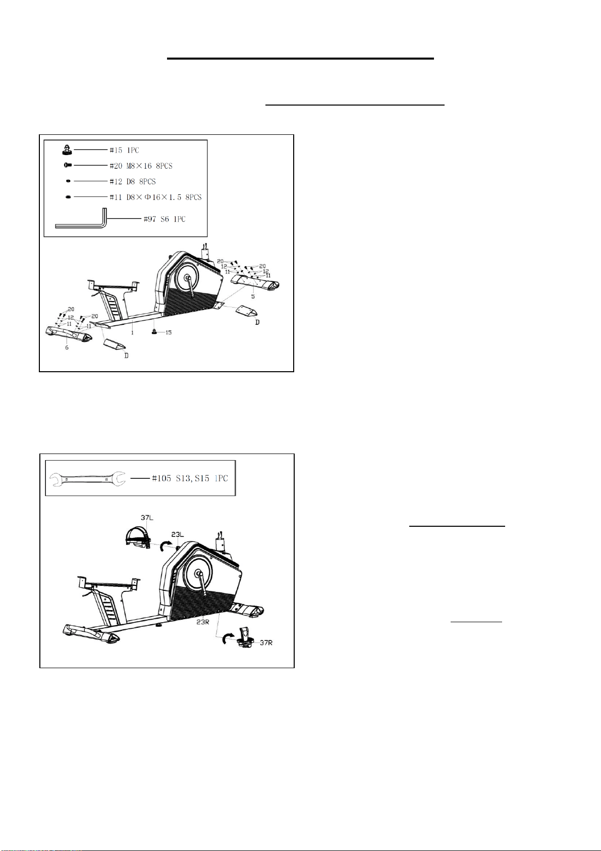
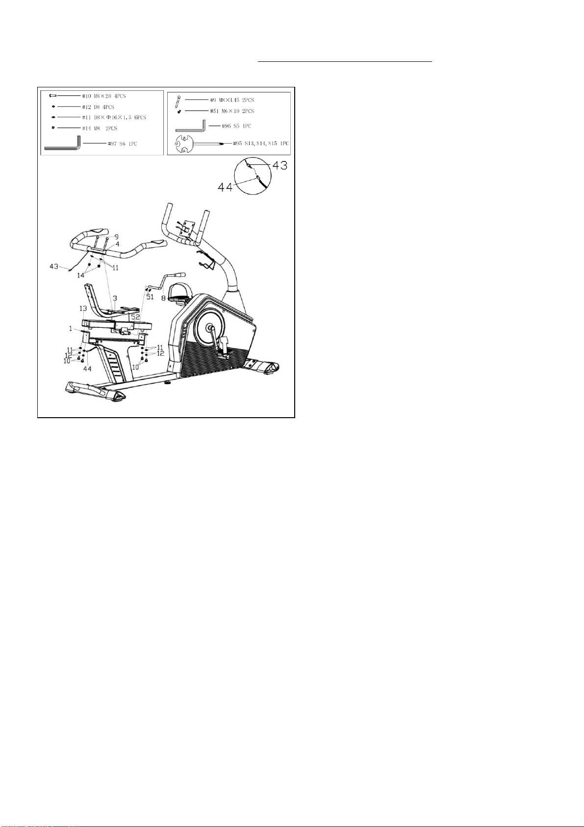
STEP 1:
Remove 2 Shipping Tubes (No. D), 8
Screws (No. 20), 8 Spring Washers (No.
12) and 8 Flat Washers (No. 11) from the
Main Frame (No. 1) using Allen Wrench
(No. 97).
NOTE: You may discard the Shipping
Tubes (No. D) or save them to repackage
the item in the future.
Attach the Front Stabilizer (No. 5) and Rear
Stabilizer (No. 6) to the Main Frame (No. 1)
with 8 Screws (No. 20), 8 Spring Washers
(No. 12) and 8 Flat Washers (No. 11) that
were just removed. Tighten and secure with
the Allen Wrench (No. 97).
Attach the Adjustable Pad (No. 15) to the
Main Frame (No. 1).
STEP 2:
Align the Left Pedal (No. 37L) with the Left
Crank (No. 23L) at 90° and gently insert the
pedal into the crank arm. Turn the Left
Pedal (No. 37L) counter-clockwise as tightly
as you can with your hands, then use
Spanner (No. 105) to tighten securely.
Align the Right Pedal (No. 37R) with the
Right Crank (No. 23R) at 90° and gently
insert the pedal into the crank arm. Turn the
Right Pedal (No. 37R) clockwise as tightly
as you can with your hands, then use
Spanner (No. 105) to tighten securely.
NOTE: Left Pedal (No. 37L) is marked with
“L” on the pedal, while Right Pedal (No.
37R) is marked with “R” on the pedal.
Attaching the Pedals (No. 37L/R) to the
Cranks (No. 23L/R) or turning them with the
wrong direction will damage the Cranks (No.
23L/R).
6
We value your experience using Sunny Health and Fitness products. For assistance with parts or
(877-907-8669).
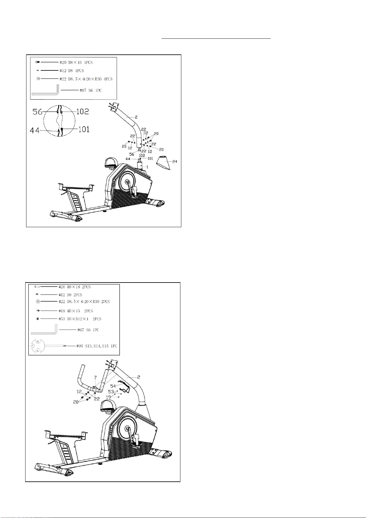
STEP 3:
Remove 4 Screws (No. 20), 4 Spring
Washers (No. 12) and 4 Arc Washers (No.
22) from the Main Frame (No. 1) using Allen
Wrench (No. 97).
Insert the Handlebar Post (No. 2) into the
Upright Tube Cover (No. 24) and move the
Upright Tube Cover (No. 24) higher.
Connect the Sensor Extension Wire 1 (No.
102) with Sensor Extension Wire 2 (No.
101), and connect Extension Wire 2 (No.
56) with Extension Wire 1 (No. 44).
Attach the Handlebar Post (No. 2) to the
Main Frame (No. 1) with 4 Screws (No. 20),
4 Spring Washers (No. 12) and 4 Arc
Washers (No. 22) that were just removed.
Tighten and secure with the Allen Wrench
(No. 97).
Move the Upright Tube Cover (No. 24)
lower so it snaps into the Main Frame (No.
1).
STEP 4:
Remove 2 Screws (No. 20), 2 Spring
Washers (No. 12) and 2 Arc Washers (No.
22) from the Handlebar Post (No. 2) using
Allen Wrench (No. 97). Then attach the
Armrest (No. 7) to the Handlebar Post (No.
2) with 2 Screws (No. 20), 2 Spring
Washers (No. 12) and 2 Arc Washers (No.
22) that were just removed. Tighten and
secure with the Allen Wrench (No. 97).
Remove 2 Screws (No. 19) and 2 Flat
Washers (No. 53) from the Handlebar Post
(No. 2) using Spanner (No. 95). Then attach
the Bottle Holder (No. 54) to the Handlebar
Post (No. 2) with 2 Screws (No. 19) and 2
Flat Washers (No. 53) that were just
removed. Tighten and secure with the
Spanner (No. 95).
7
We value your experience using Sunny Health and Fitness products. For assistance with parts or
(877-907-8669).
STEP 5:
Remove 4 Screws (No. 10), 4 Spring
Washers (No. 12) and 4 Flat Washers (No.
11) from the Rail (No. 13) with Allen
Wrench (No. 97). Then attach the Rail (No.
13) to the Main Frame (No. 1) with 4
Screws (No.10), 4 Spring Washers (No.
12) and 4 Flat Washers (No. 11) that were
just removed using Allen Wrench (No. 97).
Remove the 2 Screws (No. 51) from the
Adjustment Handle (No. 8) using Allen
Wrench (No. 96). Then attach the
Adjustment Handle (No. 8) to the Axle (No.
52) with 2 Screws (No. 51) that were just
removed using Allen Wrench (No. 96).
Remove 2 Carriage Bolts (No. 9), 2 Flat
Washers (No. 11) and 2 Cap Nuts (No. 14)
from the Handlebar (No. 4) using Spanner
(No. 95). Then attach the Handlebar (No. 4)
to the Seat Tube (No. 3) with 2 Carriage
Bolts (No. 9), 2 Flat Washers (No. 11) and
2 Cap Nuts (No. 14) that were just removed
using Spanner (No. 95).
Connect the Pulse Wire (No. 43) with the
Extension Wire 1 (No. 44).
8
We value your experience using Sunny Health and Fitness products. For assistance with parts or
(877-907-8669).
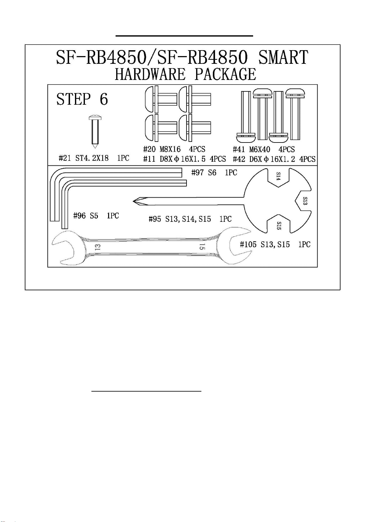
STEP 6:
Remove 2 Screws (No. 19) from the Main
Frame (No. 1) using Spanner (No. 95).
Then attach 2 Rail Covers (No. 17) to the
Main Frame (No. 1) with 2 Screws (No. 19)
that were just removed using Spanner (No.
95).
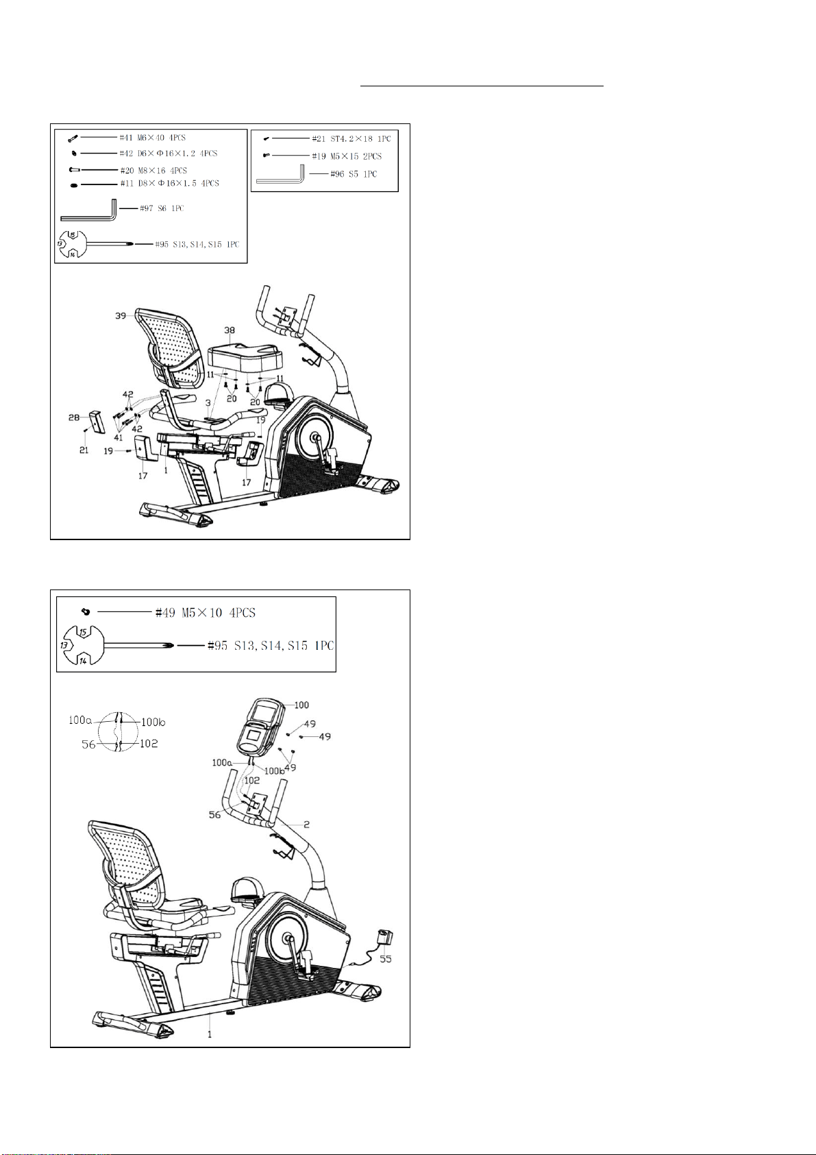
Attach the Seat (No. 38) to the Seat Tube
(No. 3) with 4 Screws (No. 20) and 4 Flat
Washers (No. 11) using Allen Wrench (No.
97).
Attach the Backrest (No. 39) to the Seat
Tube (No. 3) with 4 Bolts (No. 41) and 4
Flat Washers (No. 42). Tighten and secure
with Allen Wrench (No. 96).
Attach the Backrest Cover (No. 28) to the
Seat Tube (No. 3) with the Screw (No. 21)
using the Spanner (No. 95) to secure.
STEP 7:
Remove 4 Screws (No. 49) from the Meter
(No. 100) with Spanner (No. 95).
Connect the Extension Wire 2 (No. 56) with
Meter Wire A (No. 100a), and connect the
Sensor Extension Wire 1 (No. 102) with
Meter Wire B (No. 100b). Then attach the
Meter (No. 100) to the bracket of Handlebar
Post (No. 2) with 4 Screws (No. 49) that
were just removed. Tighten and secure with
the Spanner (No. 95).
NOTE: Insert all wires to the tube of
Handlebar Post (No. 2). Do not cut or pinch
any wires when attaching the Meter (No.
100)
Insert the jack from Adapter (No. 55) to
adapter input on the back of Main Frame
(No. 1), then plug the Adapter (No. 55) into
an outlet.
The assembly is now complete!
9
ADJUSTMENT GUIDE
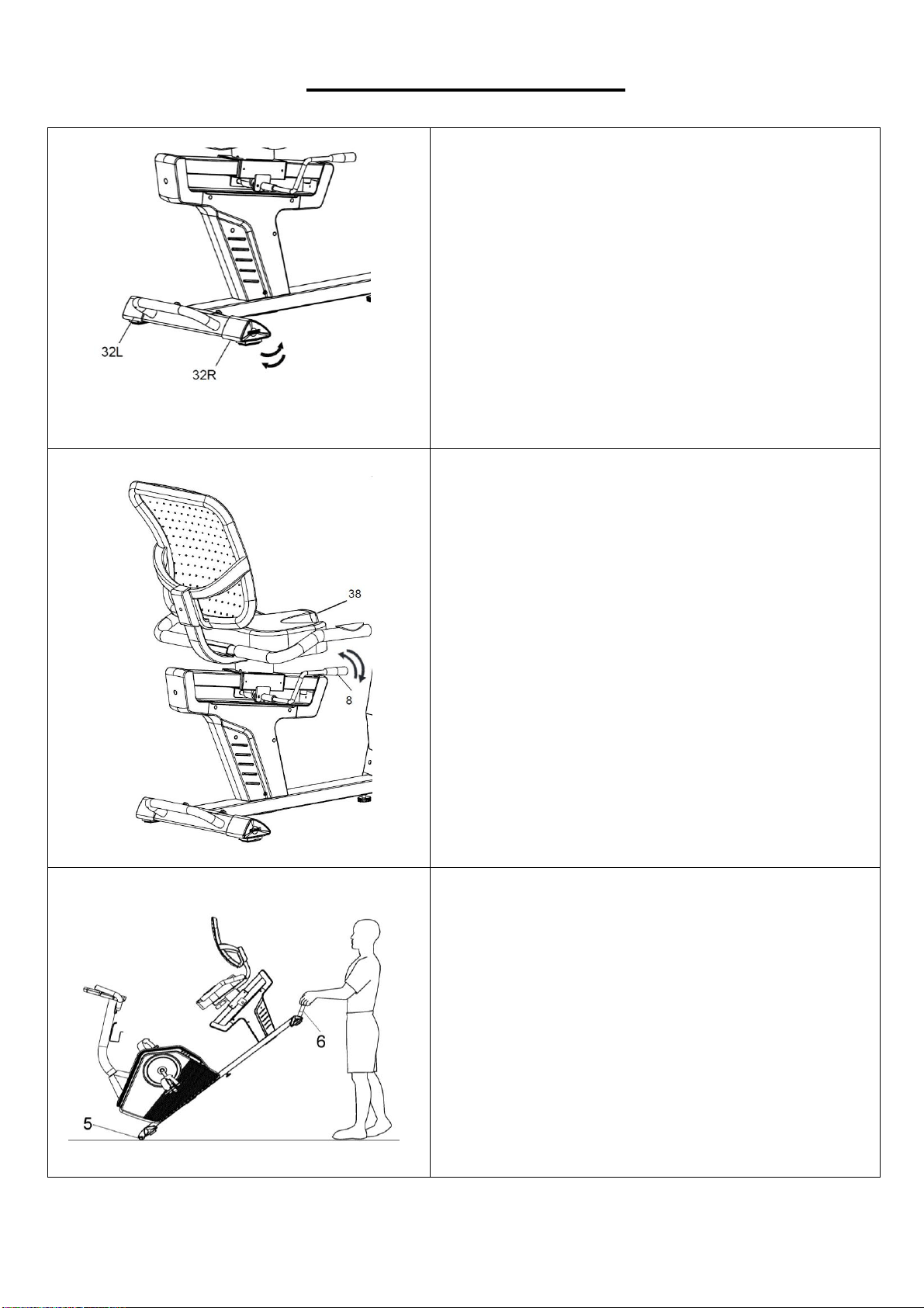
ADJUSTING THE BALANCE
In order to achieve a smooth and comfortable ride,
you must ensure that the bike is stabled and
secured. If you notice that the bike is unbalanced
during use, you should adjust the Rear End Caps
(No. 32L/R) located beneath the rear stabilizer. To
do so, simply turn the dials on the Rear End Caps
(No. 32L/R) until the bike becomes levelled with the
floor surface. Turn counter-clockwise to raise and
turn clockwise to lower.
ADJUSTING THE SEAT
To move the Seat (No. 38) forward or backward,
while seated on the bike, put your feet on the floor.
Shift the Adjustment Handle (No. 8) down to
loosen. Move the Seat (No. 38). Shift the
Adjustment Handle (No. 8) up to secure.
MOVING THE BIKE
There are wheels located on the Front Stabilizer
(No. 5). Hold the handlebar on the Rear Stabilizer
(No. 6) and pull forward to lift the rear of the
recumbent bike off the floor. Now you can move the
recumbent bike.
10
IMPORTANT RECUMBENT BIKE INFORMATION
WARNING: This recumbent bike requires a power source of 1 amp (100-240V) in order to
properly operate. For your safety, as well as the safety of others, please verify that the power
source is correct before plugging in the equipment. Any power source above or below this level
could cause significant damage to the equipment and or user.
OPERATING INSTRUCTIONS
Plug the adaptor into the recumbent bike and into the outlet.
The meter will turn on.
The meter will turn off if there is no activity for 4 minutes. Press any
button on the meter to turn it on again.
NOTE: You can still use the recumbent bike when it is not plugged in.
However, the meter will not be working and you cannot adjust the
resistance level or use any of the functions.
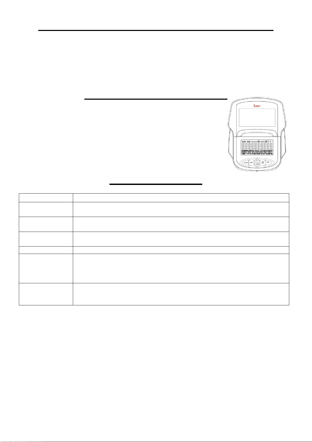
EXERCISE METER
KEY FUNCTIONS:
BUTTON
FUNCTION
START/STOP
Start and pause workouts
Start body fat measurement
DOWN
Lower the resistance level during workout.
Decrease value of selected parameter
UP
Increase the resistance level during workout.
Increase value of selected parameter
ENTER
Input the value or mode
RECOVERY
Enter Recovery function when the meter displays the heart rate value.
Recovery displays F1-F6
F1 is excellent recovery heart rate
F6 is poor recovery heart rate
MODE
During workout, switch display from RPM to SPEED, ODO to DIST and
WATT to CALORIES
Hold for 3 seconds to reset all function values to zero, except ODO.
WORKOUT SELECTION:
After turning the meter on by plugging in the adaptor or if already plugged in, pressing any button
on the meter, use the UP or DOWN button to make a selection. Then press ENTER button to
choose the desired mode.
There are 7 basic workout modes:
Manual, Pre-set Programs, Watt Program, Body Fat Program, Target Heart Rate Program, Heart
Rate Control Programs, and User Programs.
FUNCTIONS:
SPEED: Displays current training speed. Maximum speed is 99.9 MPH.
RPM: Displays current rotation per minute.

11
TIME: Accumulates the workout time from 0:00 to 99:59. Users can preset the target time they
want.
DIST (DISTANCE): Accumulates the workout distance from 0.00 to 999.9 Miles. Users can preset
the target distance they want to reach.
ODO (ODOMETER): Displays the total accumulated distance from 0 to 9999 Miles.
CAL (CALORIES): Accumulates the calories burned from 0 to 9999. Users can preset the target
calories they want to burn.
WATT: Displays current watt.
HEART RATE: Displays the current heart rate in beats per minute.
TARGET HR. (TARGET HEART RATE): Users can preset their Target Heart Rate.
PROGRAM: There are 24 different programs to choose for training.
LEVEL: The program has 10 columns of bars and 8 bars in each column. Each column
represents a 1-minute workout and each bar represents 2 resistance levels.
WORKOUT PARAMETERS:
TIME / DISTANCE / CALORIES / AGE / WATT / TARGET HEART RATE
Setting Workout Parameters
After selecting the desired workout mode: Manual Programs, Pre-set Programs, Watt Control
Program, Body Fat Program, Target Heart Rate Program, Heart Rate Control Programs, and User
Programs. You may pre-set several workout parameters for desired results.
NOTE: Some parameters are not adjustable in certain programs. Time and Distance cannot
be set up at the same time.
Once a program has been selected, press ENTER button and TIME will flash.
Using the UP or DOWN button, you may select the desired time value. Press ENTER button to
input the values. The flashing prompt will move to the next parameter. Continue using the UP or
DOWN button. Press the START/STOP button to begin the workout.
More About Setting Workout Parameters
Field
Setting Range
Default
Value
Increment/
Decrement
Description
TIME
0:00~99:00
0:00
±1:00
1..When display is set as 0:00,
TIME will count up.
2..When TIME is set as 1:00-99:00,
it will count down to 0.00.
DIST
(DISTANC
E)
0.00~999.0
0.00
±1.00
1..When display is set as 0.00,
DISTANCE will count up.
2..When DISTANCE is set as
1.00~999.0, it will count down
to 0.00.
12
CAL
(CALORIE
S)
0.00~9995
0.00
±5 .00
1..When display is set as 0.00,
CALORIES will count up.
2. When CALORIES is set as
5.00~9995, it will count down to
0.00.
WATT
50~250
100
±5
User can set watt value only in
the Watt Control Program.
AGE
10~99
30
±1
Target HR will be based on Age.
When Heart Rate exceeds Target
HR, the Heart Rate number will
flash.
TARGET
HEART
RATE
60~220
90
±1
Setting Parameters for Target
Heart Rate.
PROGRAM OPERATION:
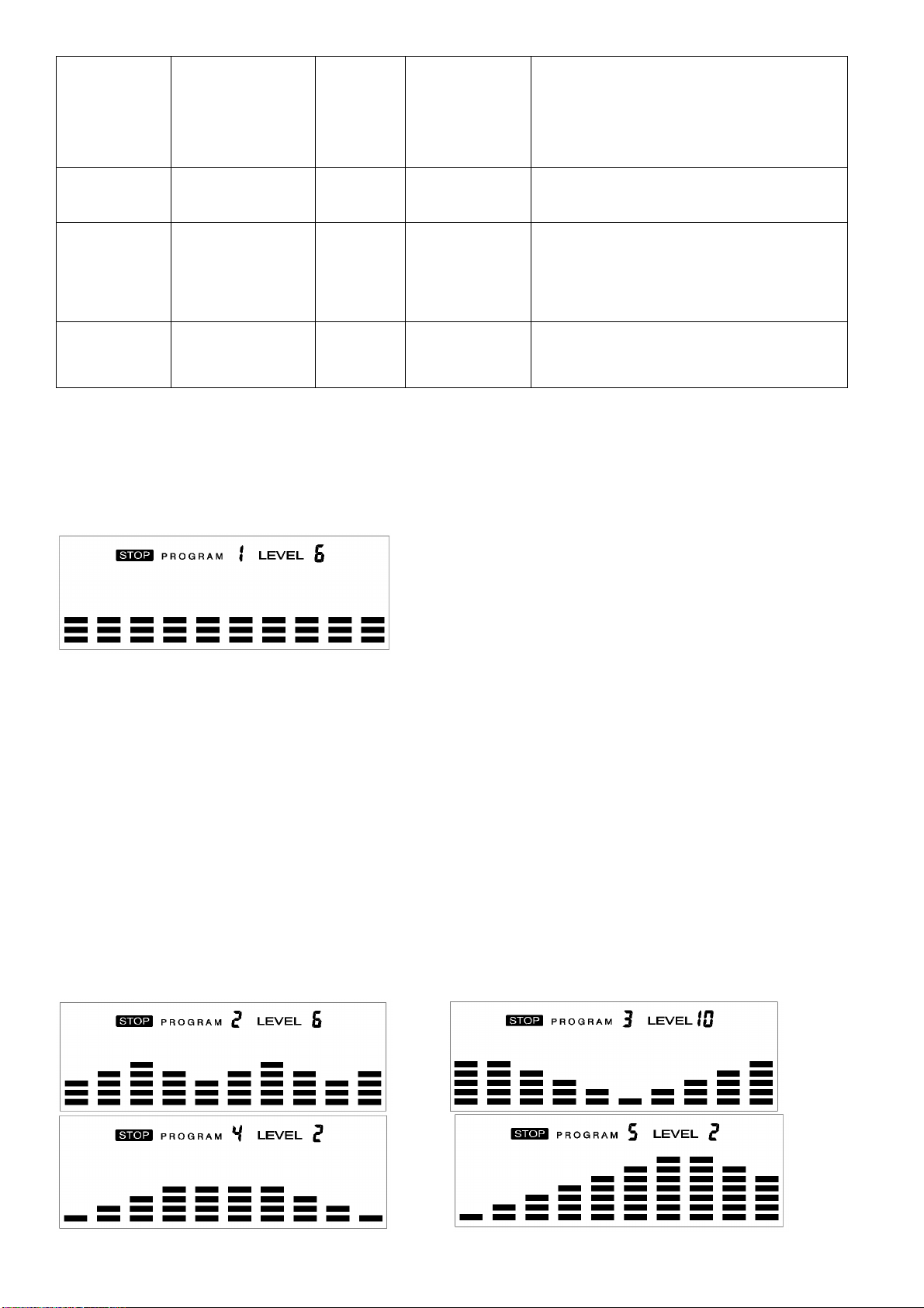
MANUAL PROGRAM (P1)
Program profile
SETTING PARAMETERS FOR MANUAL PROGRAM
1. Select Manual Program (P1) using the UP or DOWN button, then press ENTER button.
2. TIME will flash so the value can be adjusted using the UP or DOWN button.
3. Press the ENTER button to save the value and move to the next parameter to be adjusted.
NOTE: If you set up the target time for workout, then the next parameter of DISTANCE
cannot be adjusted.
4. Continue through all desired parameters and press the START/STOP button to begin the
workout.
NOTE: Once the workout parameter counts down to zero, it will beep and stop the
workout automatically. Press the START button to continue the workout to reach the
unfinished workout parameter.
PRE-SET PROGRAMS (P2~P13)
Program profile
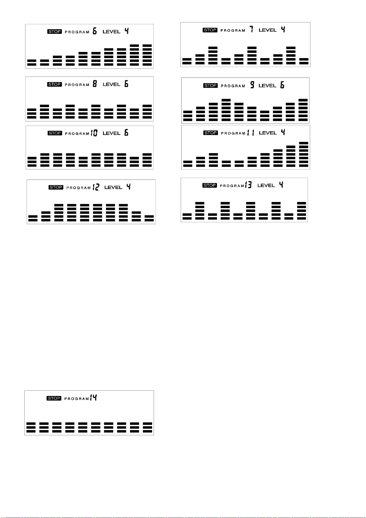
13
There are 12 pre-set programs ready for use. All program profiles have 16 levels of
resistance.
SETTING PARAMETERS FOR PRE- SET PROGRAMS
1. Select one of the Pre-set Programs using the UP or DOWN button, then press ENTER button.
TIME will flash so the value can be adjusted using the UP or DOWN key.
2. Press the ENTER button to save value and move to the next parameter to be adjusted. Continue
through all desired parameters, pressing the START/STOP button to begin the workout.
Workout in any pre-set program
You can adjust the level of resistance by pressing the UP or DOWN button during the workout.
NOTE: If you set up the target time for workout, then the next parameter of DISTANCE
cannot be adjusted. Once the workout parameter counts down to zero, it will beep and stop
the workout automatically. Press the START button to continue the unfinished parameter.
WATT CONTROL PROGRAM (P14)
Program profile
SETTING PARAMETERS FOR THE WATT CONTROL PROGRAM
1. Select Watt Control Program (P14) using the UP or DOWN button, then press ENTER button.
2. TIME will flash so the value can be adjusted using the UP or DOWN button.
14
3. Press ENTER button to save the value and move to the next parameter to be adjusted.
NOTE: If you set up the target time for workout, then the next parameter of DISTANCE
cannot be adjusted.
4. Continue through all desired parameters, pressing the START/STOP button to start the workout.
NOTE: Once the workout parameters count down to zero, it will beep and stop the
workout automatically.
5. Press the START button to continue the workout to reach the unfinished workout parameter.
The meter will adjust the resistance load automatically depending on the speed to
maintain the constant watt value. You can use the UP or DOWN button to adjust the watt
value during the workout.
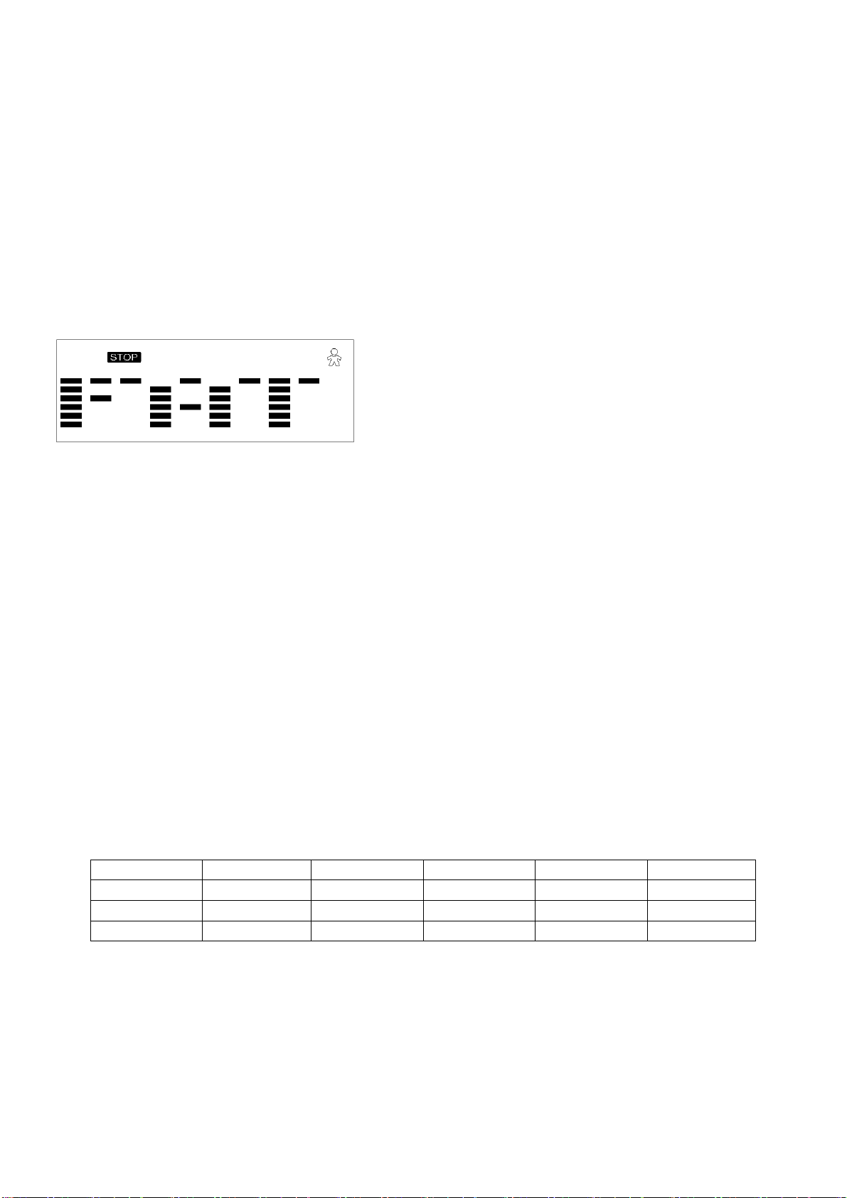
BODY FAT PROGRAM (P15)
Program profile
SETTING DATA FOR BODY FAT
Select BODY FAT Program (P15) using the UP or DOWN button, then press ENTER button.
“MALE” will flash so Gender can be adjusted using the UP or DOWN button. Press the ENTER
button to save gender and move to the next data.
“5’8 (inches)” of Height will flash so Height can be adjusted using the UP or DOWN button. Press
ENTER button to save the value and move to the next data.
“154 (lbs)” of Weight will flash so Weight can be adjusted using the UP or DOWN button. Press
ENTER button to save the value and move to the next data.
“30” of Age will flash so Age can be adjusted using the UP or DOWN button. Press ENTER button
to save the value.
Press the START/STOP button to start the measurement. Please also remember to grasp the hand
pulse sensors. After 15 seconds the display will show Body Fat %, BMR, BMI, & BODY TYPE.
Body Types:
There are 9 body types divided according to the FAT % calculated.
Body Type
FAT %
Body Type
FAT %
Body Type
FAT %
Type 1
5% - 9%
Type 4
20% - 24%
Type 7
35% - 39%
Type 2
10% - 14%
Type 5
25% - 29%
Type 8
40% - 44%
Type 3
15% - 19%
Type 6
30% - 34%
Type 9
45% - 50%
BMR: Basal Metabolism Ratio
BMI: Body Mass Index
Press START/STOP button to return the main display.
15
TARGET HEART RATE PROGRAM (P16)
Program profile
SETTING PARAMETERS FOR TARGET HEART RATE PROGRAM
1. Select TARGET HR (P16) using the UP or DOWN button, then press ENTER button.
2. TIME will flash. The value can be adjusted using the UP or DOWN button.
3. Press the ENTER button to save the value and move to the next parameter to be adjusted.
NOTE: If you set up the target time to workout, then the next parameter of DISTANCE
cannot be adjusted.
4. Continue through all desired parameters, pressing START/STOP button to start workout.
NOTE: If heart rate is above the set TARGET HR, the Pulse value will flash to remind the
user.
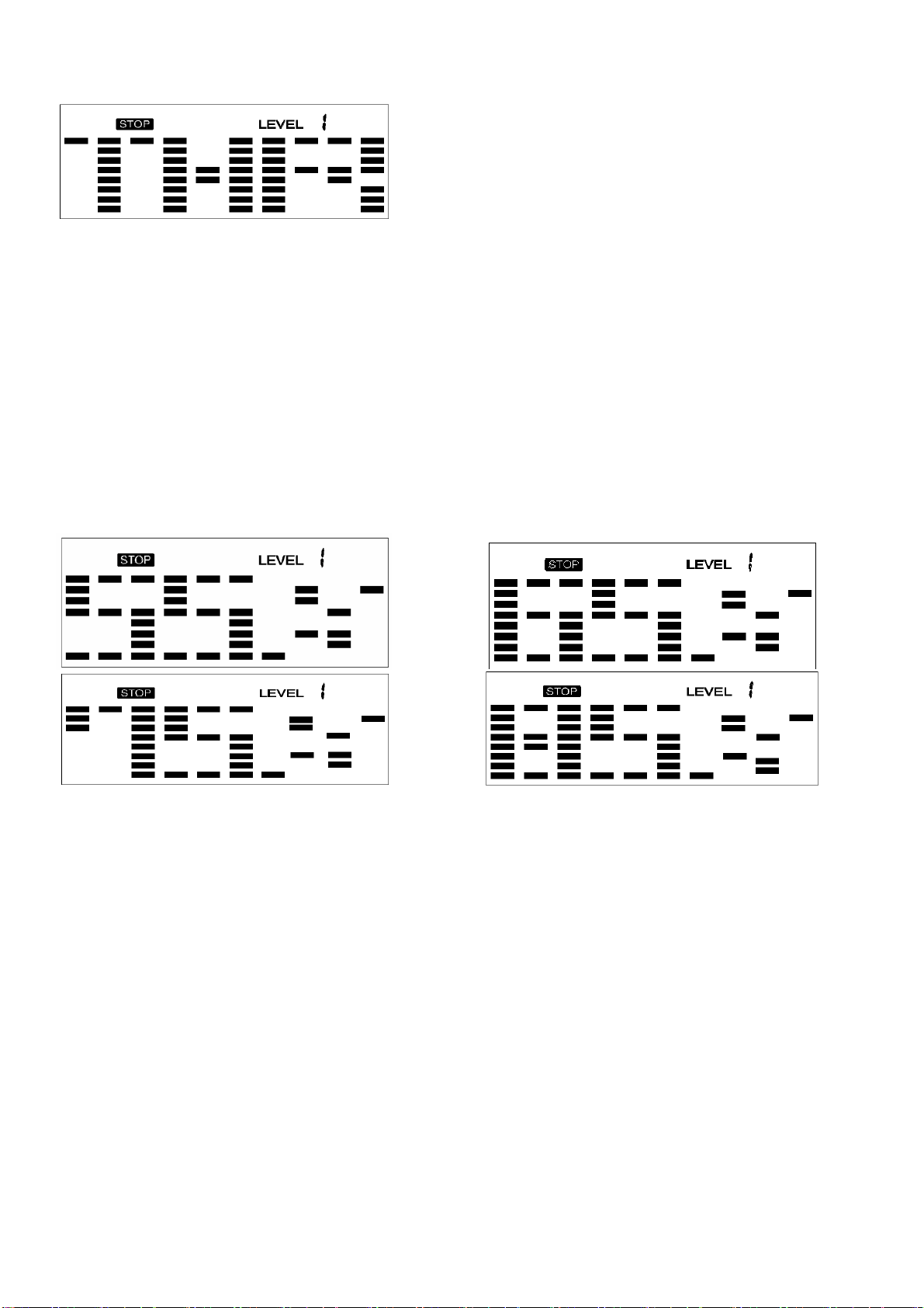
HEART RATE CONTROL PROGRAM (P17-P20)
Program profile
There are 4 selections for target pulse (HR):
HRC - 55% TARGET HR= 55% of (220-AGE)
HRC - 65% TARGET HR= 65% of (220-AGE)
HRC - 75% TARGET HR= 75% of (220-AGE)
HRC - 85% TARGET HR= 85% of (220-AGE)
SETTING PARAMETERS FOR HEART RATE CONTROL
1. Select one of the Heart Rate Control Programs using the UP or DOWN button, then press
ENTER button.
2. TIME will flash. The value can be adjusted using the UP or DOWN button.
3. Press the ENTER button to save the value and move to the next parameter to be adjusted.
NOTE: If you set up the target time to work out, then the next parameter of DISTANCE
cannot be adjusted.
4. Continue through all desired parameters, pressing the START/STOP button to start the workout.
NOTE: If heart rate is above or below (± 5) the TARGET HR, the meter will adjust the
resistance load automatically. It will check every 20 seconds approx. 1 resistance load
will increase or decrease (NOTE: each resistance load represents 2 levels of loading).
If one of the workout parameters counts down to zero, it will beep and stop the workout
automatically. Press the START/STOP button to continue the workout to reach unfinished
workout parameter.
16
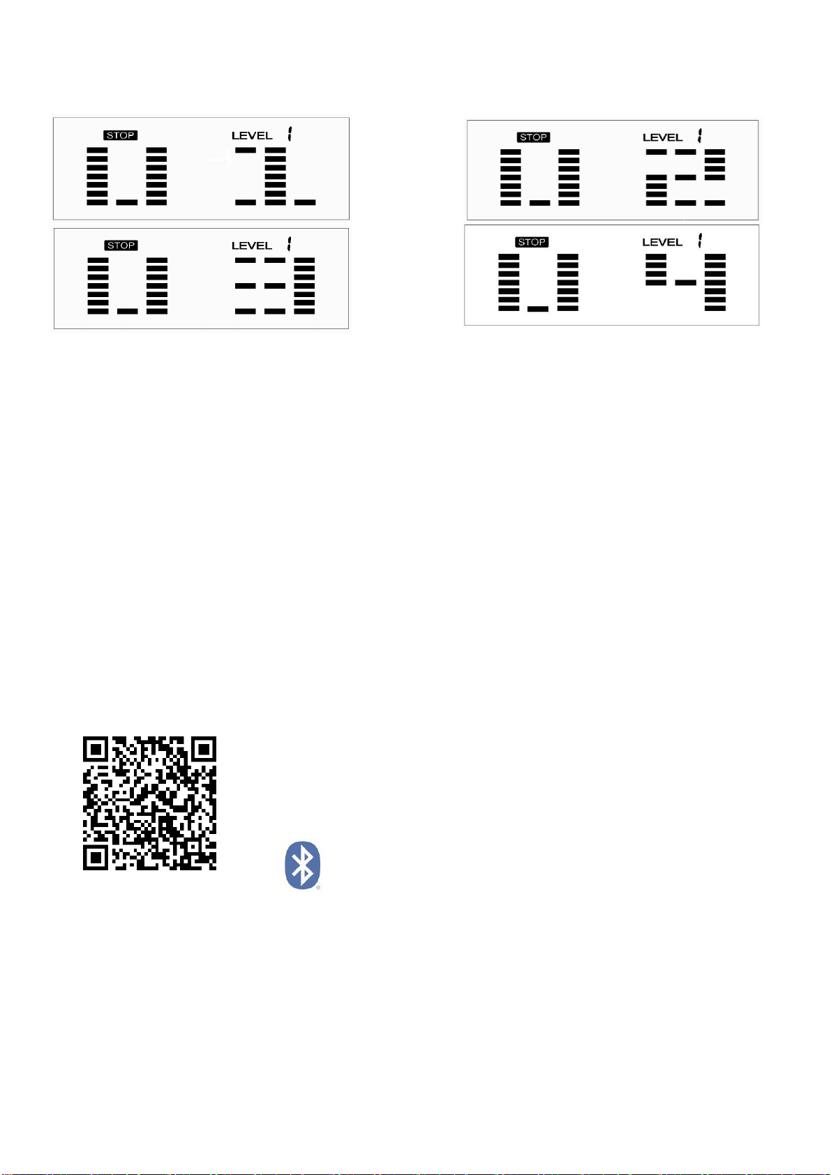
USER PROGRAM
Program profile (P21-P24)
The 4 user programs allow the user to set their own program that can be used immediately.
SETTING PARAMETERS FOR USER PROGRAM
1. Select the User Program using the UP or DOWN button then press ENTER button.
2. TIME will flash so the value can be adjusted using the UP or DOWN button.
3. Press the ENTER button to save the values and move to the next parameter to be adjusted.
NOTE: If you set up the target time to work out, then the next parameter of DISTANCE
cannot be adjusted.
4. Continue through all desired parameters.
5. After finishing the setup of the desired parameters, level 1 will flash. Use the UP or DOWN
button to adjust, then press the ENTER button until finished. (There are 10 times total). Press
the START/STOP button to begin the workout.
NOTE: Once the workout parameter counts down to zero, it will beep and stop the
workout automatically. Press the START/STOP button to continue the workout to reach
the unfinished workout parameter.
APP CONNECTION:
1. Scan the QR code below to enter the app store and download the SunnyFit app to your
mobile phone.
2. Ensure that the Bluetooth function is turned on from your phone.
3. If this is your first time using the SunnyFit app, follow the in-app instructions to register for your
free SunnyFit account and log in.
4. To connect the equipment to the SunnyFit app:
a. From the “Workout” tab, press on the “Search” button to search for your equipment.
b. Once your equipment appears on the list, tab on the “Select” button.
c. NOTE: If your equipment does not appear on the "Searching for Equipment" list, check the
EXERCISE METER on your equipment to ensure that it is not in sleep mode and your
phone's Bluetooth function is on, then tap "Retry" to search again.
d. Once your equipment shows up on the “Workout” tab as “Currently Selected”, your
equipment is now ready to display, track, and record your equipment’s workout stats on the
app!

17
TROUBLESHOOTING
PROBLEM
POSSIBLE CAUSE
CHECK
SOLUTION
E1-1
The motor couldn’t find
its start point.
Check if all the cables are
well plugged in, or check if
the pins on the cables are
improperly inserted, or check
if the motor is well
connected.
Plug in the cables again
and power on, then
press MODE and
ENTER buttons at the
same time to enter the
correction mode to
correct errors.
E1-2
The motor signal has no
induction.
Check if all the cables are
well plugged in, or check if
the pins on the cables are
improperly inserted, or check
if the motor is stuck.
Plug in the cables again
or change a new motor.
E1-3
The motor has exceed
the maximum
resistance level.
Check if all the cables are
well plugged in, or check if
the pins on the cables are
improperly inserted.
Plug in the cables again
and power on, 1 second
later disconnect the
cables then re-plug in
the cables and power on
again, wait about 6
seconds let the motor
come back to its start
point, then press MODE
and ENTER buttons at
the same time to enter
the correction mode to
correct errors.
E2
No EEPROM data was
read.
Re-connect the meter.
The EEPROM data
reading error.
Power on the meter
again to re-read the
data.
E4
Hands aren’t put on the
two handle pulses
immediately after
pressing START button.
Put the hands on the
two handle pulses
immediately after
pressing START button.
Body Fat Function
cannot receive the
signal for pulse.
Check if the handle pulse
wires are well connected.
Plug in the handle pulse
wires again or change
the handle pulse wires.
Check if the pulse is working
when not in Body Fat
Program.
Change the meter.
NOTE: If you are unable to resolve an issue using the troubleshooting guide above, please
contact Customer Service at [email protected].
18
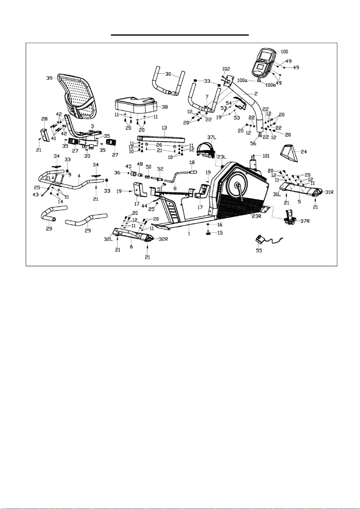
EXPLODED DIAGRAM 1
19
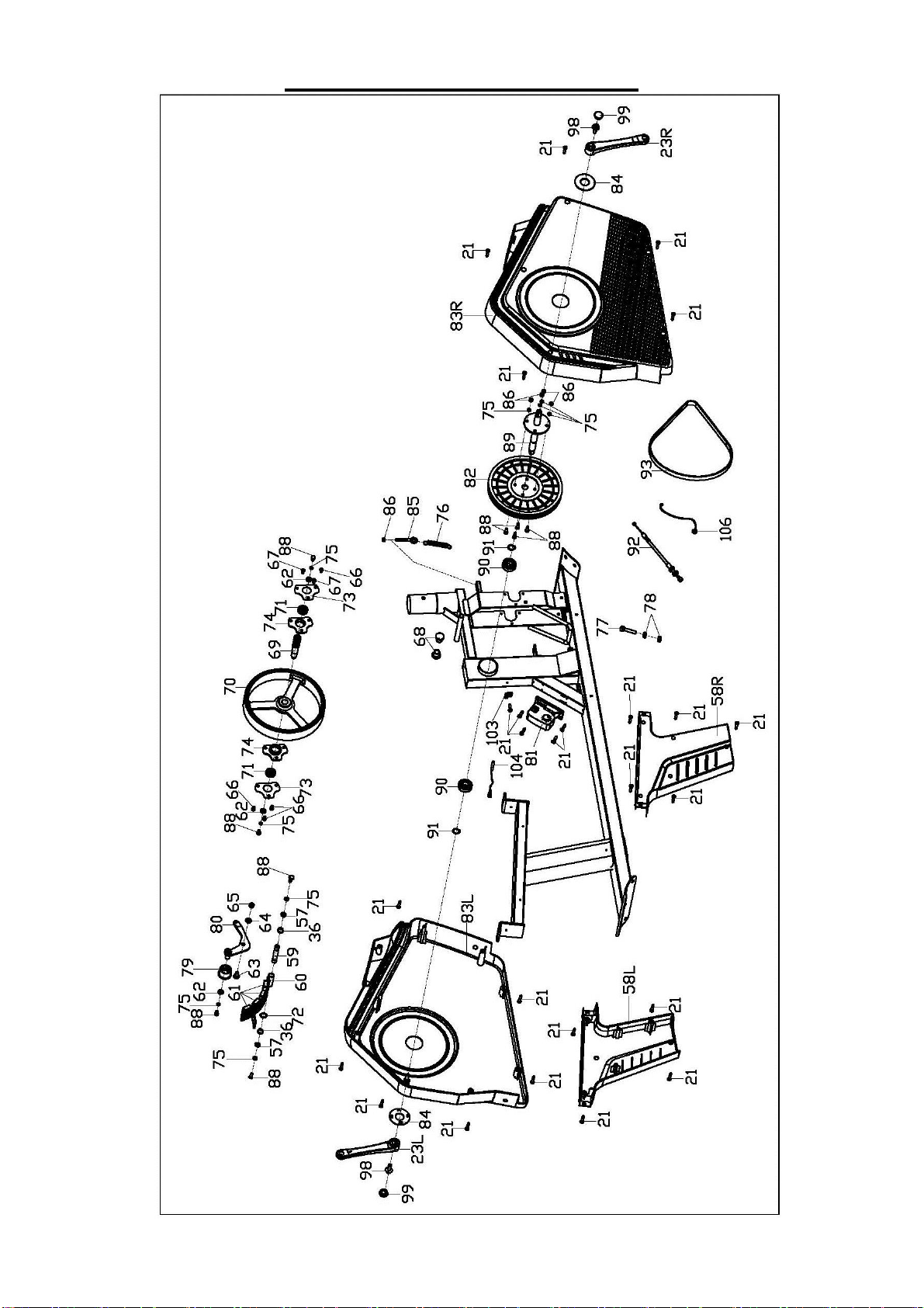
EXPLODED DIAGRAM 2
20
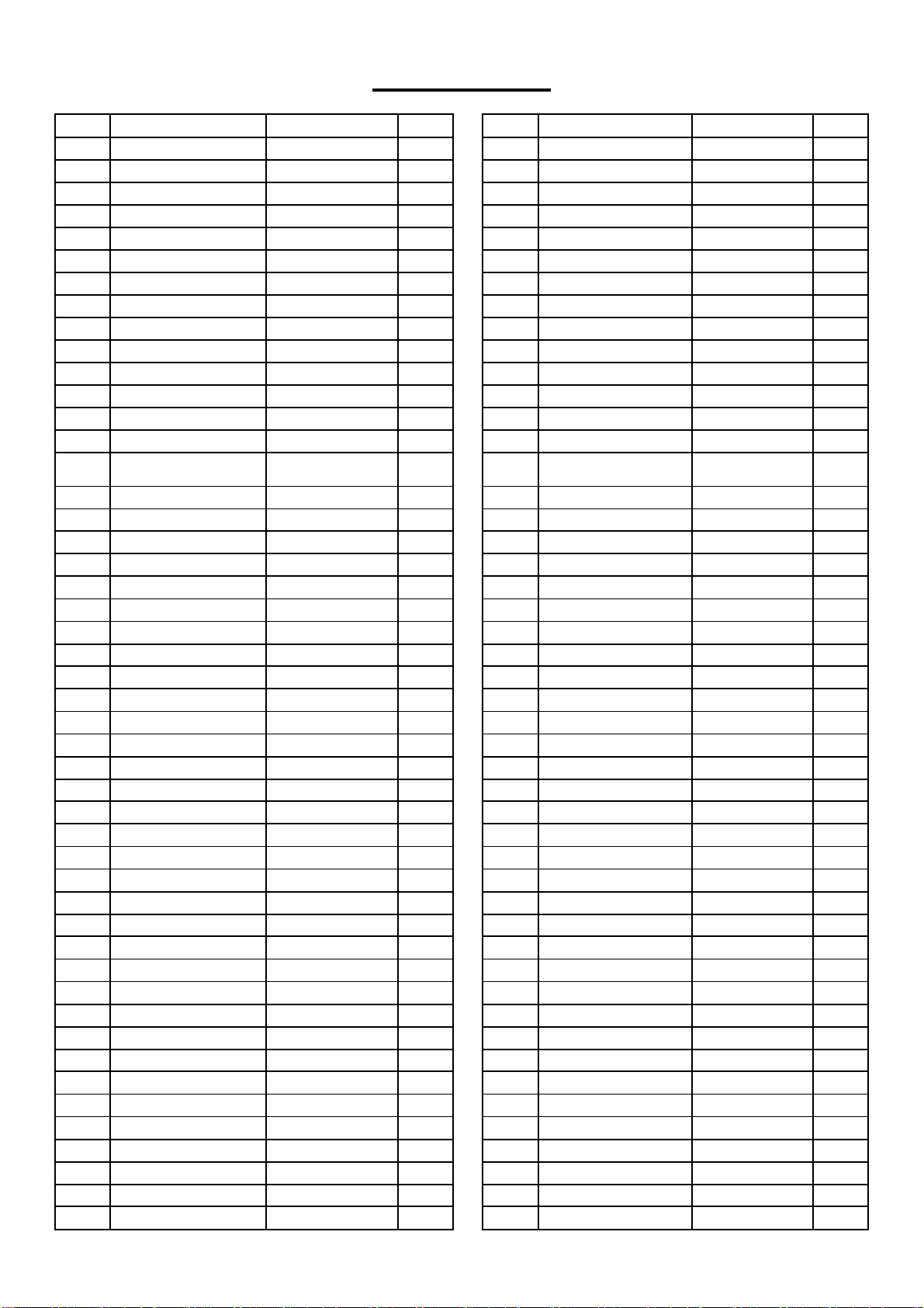
PARTS LIST
No.
Description
Spec.
Qty.
No.
Description
Spec.
Qty.
1
Main Frame
1
49
Screw
M5X10
4
2
Handlebar Post
1
50
Plate
1
3
Seat Tube
1
51
Allen Screw
M6X10
2
4
Handlebar
1
52
Axle
1
5
Front Stabilizer
1
53
Flat Washer
D5XD12X1
2
6
Rear Stabilizer
1
54
Bottle Holder
1
7
Armrest
1
55
Adaptor
1
8
Adjustment Handle
1
56
Extension Wire 2
1
9
Carriage Bolt
M8XL45
2
57
Flat Washer
D6XФ12X1
2
10
Screw
M8X20
4
58L/R
Seat Bracket Cover
1 pr.
11
Flat Washer
D8XФ16X1.5
18
59
Magnetic Board Axle
1
12
Spring Washer
D8
18
60
Magnetic Board
1
13
Rail
1
61
Square Magnet
4
14
Cap Nut
M8
2
62
Flat Washer
D6XФ16X1.5
3
15
Adjustable Pad
1
63
Bolt
Ф14XФ10XM8X
20.5
1
16
Hex Nut
M10
1
64
Flat Washer
D10XФ14X1
1
17
Rail Cover
2
65
Nylon Nut
M8
1
18
Foam Grip
1
66
Screw
M6X10
4
19
Screw
M5X15
4
67
Screw
M6X8
2
20
Screw
M8X16
18
68
Plug
Ф25X22
2
21
Screw
ST4.2X18
34
69
Flywheel Axle
1
22
Arc Washer
D8.5XФ20XR30
6
70
Flywheel
1
23L/R
Crank
1 pr.
71
Bearing
2
24
Upright Tube Cover
1
72
Wave Washer
Ф12XФ15.5X0.3
1
25
Plug
2
73
Fixed Plate
2
26
Cushion
2
74
Bearing Block
2
27
Bushing
2
75
Spring Washer
D6
5
28
Backrest Cover
1
76
Tension Spring
Ф3.0XФ18.5X79
1
29
Foam Grip
Ф30XФ24X550
2
77
Bolt
M5X60
1
30
Foam Grip
Ф30XФ24X380
2
78
Hex Nut
M5
2
31L/R
Front End Cap
1 pr.
79
Idler Wheel
1
32L/R
Rear End Cap
1 pr.
80
Idler Wheel Linkage
1
33
Round Cap
4
81
Gear Motor
1
34
Pulse Sensor
2
82
Belt Pulley
1
35
Screw
ST3.5X8
4
83L/R
Belt Cover
1 pr.
36
Axle Spring Washer
3
84
Crank Cover
2
37L/R
Pedal
1 pr.
85
Adjusting Bolt
M6X50
1
38
Seat
1
86
Nylon Nut
M6
5
39
Backrest
1
87
N/A
40
Refer to #100
88
Hex Screw
M6X15
9
41
Bolt
M6X40
4
89
Middle Axle
Ф17X196
1
42
Flat Washer
D6XФ16X1.2
4
90
Bearing
6203RS
2
43
Pulse Wire
1
91
Axle Spring Washer
D17
2
44
Extension Wire 1
1
92
Tension Wire
1
45
Upper Block
1
93
Belt
1
46
Refer to #101
94
N/A
47
Refer to #102
95
Spanner
S13,S14,S15
1
48
Wheel
1
96
Allen Wrench
S5
1

21
No.
Description
Spec.
Qty.
No.
Description
Spec.
Qty.
97
Allen Wrench
S6
1
101
Sensor Extension Wire
2
1
98
Flange Nut
2
102
Sensor Extension Wire
1
1
99
Crank Cap
2
103
Sensor Seat
1
100
Meter
1
104
Sensor Wire
1
100a
Meter Wire A
1
105
Spanner
S13,S15
1
100b
Meter Wire B
1
106
DC Cable
1
Version 3.0

22