VERSION A0
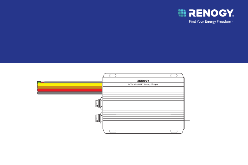
Dual Input DC-DC On-Board with MPPT Battery Charger
Renogy
12V/24V 50A IP67
RBC2125DS-21W
QUICK GUIDE
Before Getting Started
The quick guide provides important operation and maintenance instructions for Renogy 12V/24V
50A IP67 Dual Input DC-DC On-Board with MPPT Battery Charger (hereinafter referred to as
battery charger).
Read the quick guide carefully before operation and save it for future reference. Failure to
observe the instructions or precautions in the quick guide can result in electrical shock, serious
injury, or death, or can damage the battery charger, potentially rendering it inoperable.
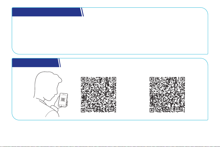
Online Manual
Quick Guide User Manual

What’s In the Box?............................................................................................................................ 1
Dimensions .......................................................................................................................................2
Get to Know Renogy Battery Charger ...........................................................................................3
System Setup ...................................................................................................................................5
Required Tools ..................................................................................................................................6
How to Install the 5/16 in Lugs (M8 Ring Terminals)? .................................................................7
How to Install Cables on the Battery Charger? ............................................................................9
Step 1. Plan a Mounting Site .........................................................................................................10
Step 2. Connect the Battery Charger to an Auxiliary Battery ................................................. 11
Step 3. Connect the Battery Charger to a Solar Panel ..............................................................13
Step 4. Connect the Battery Charger to a Starter Battery ......................................................15
Step 5. Tape over the Negative Common Cable .......................................................................... 17
Step 6. Install a Battery Temperature Sensor ............................................................................ 18
LED Indicators ................................................................................................................................19
Set a Battery Type ........................................................................................................................ 20
Table of Contents

USER Mode ...................................................................................................................................... 21
Monitor the Battery Charger ....................................................................................................... 22
Short-Range Monitoring via DC Home App ................................................................................. 23
Wireless Long-Range Monitoring ................................................................................................... 24
Important Safety Instructions ................................................................................................... 25
Renogy Support .............................................................................................................................27
FCC Statement ...............................................................................................................................29
FCC Radiation Exposure Statement ........................................................................................... 30
Disclaimer ...................................................................................................................................... 30
— 1 —
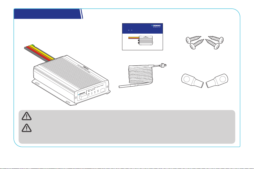
What’s In the Box?
VERSION A0
Dual Input DC-DC On-Board with MPPT Battery Charger
Renogy
12V/24V 50A IP67
RBC2125DS-21W
QUICK GUIDE
Renogy 12V/24V 50A IP67
Dual Input DC-DC On-Board
with MPPT Battery Charger × 1
Quick Guide × 1
5/16 in Lugs
(M8 Ring Terminals) × 4
Battery Temperature
Sensor (3 m) × 1
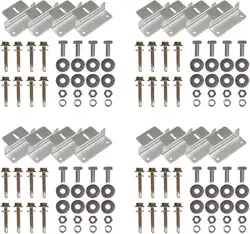
Mounting Screws x 4
ST4*20 mm
Make sure that all accessories are complete and free of any signs of damage.
The accessories and product manual listed are crucial for the installation, excluding
warranty information and any additional items. Please note that the package contents
may vary depending on the specific product model.
— 2 —
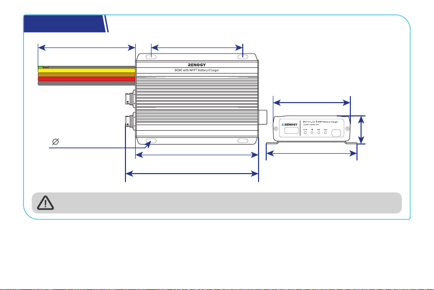
Dimensions
6.5 in (165 mm)
7 in (178 mm)
4.84 in (123 mm)
0.2 in (5 mm)
4.06 in (103 mm)
4.72 in (120 mm)
1.46 in
(37 mm)
12 in (305 mm)
Dimension tolerance: ±0.2 in (0.5 mm)
— 3 —
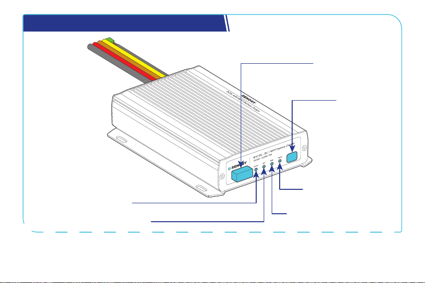
Get to Know Renogy Battery Charger
Battery Type
Setting Button
Battery Type Indicator
Auxiliary Battery Indicator
Alternator Charging Indicator
Solar Charging Indicator
Bluetooth Antenna
— 4 —
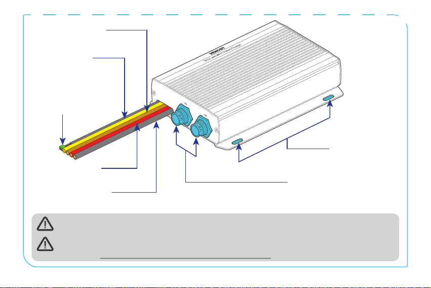
Mounting Holes
CAN Communication Ports
Battery Temperature
Sensor Cable
(with connectors)
Positive Starter
Battery Cable (red)
Negative Common
Cable (black)
Positive Solar
Cable (yellow)
Positive Auxiliary
Battery Cable (brown)
The battery temperature sensor cable can only be used with lead-acid batteries.
For CAN Communication Ports wiring details, refer to the user manual of the battery
charger at https://www.renogy.com/support/downloads.
— 5 —
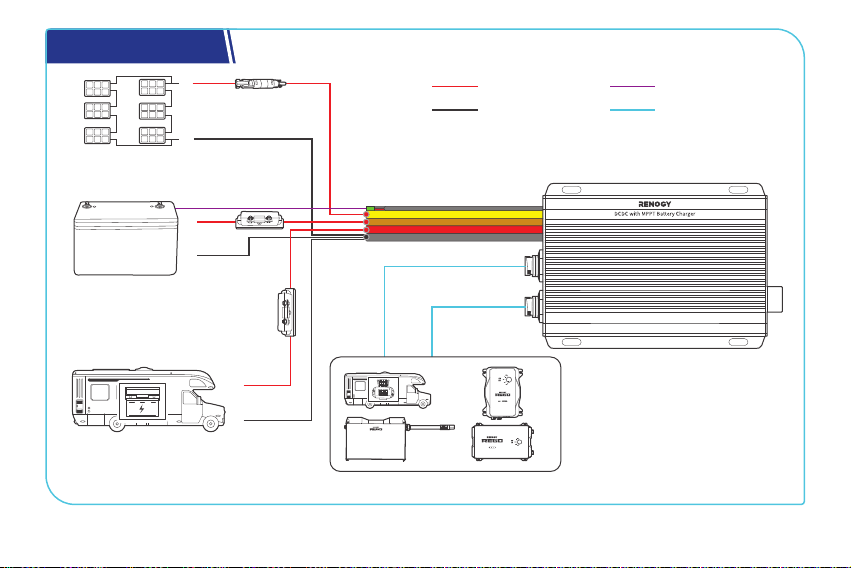
System Setup
RV-C or REGO Series Devices
Solar Panel (s)
Auxiliary Battery
(12V / 24V)
Starter Battery
DC-DC Battery Charger
+
-
+
-
+
-
Communication
Temperature
Negative
Positive
— 6 —
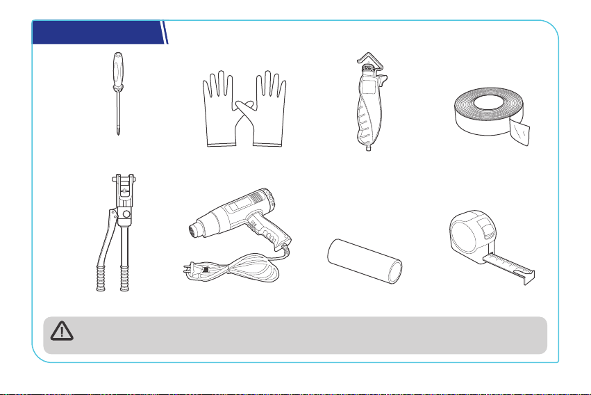
Required Tools
Measuring Tape
Insulation Tape
3
4
5
6
Insulating Gloves
Phillips
Screwdriver (#1)
Wire stripper
Manual Hydraulic Pliers
Heat Gun Heat Shrink Tubing
Prior to installing and configuring the battery charger, prepare the recommended tools,
components, and accessories.
— 7 —
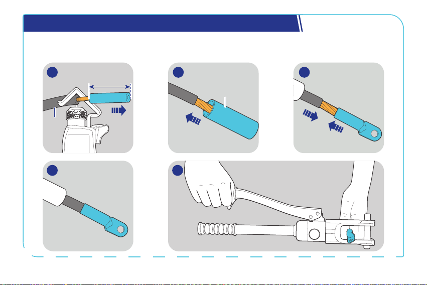
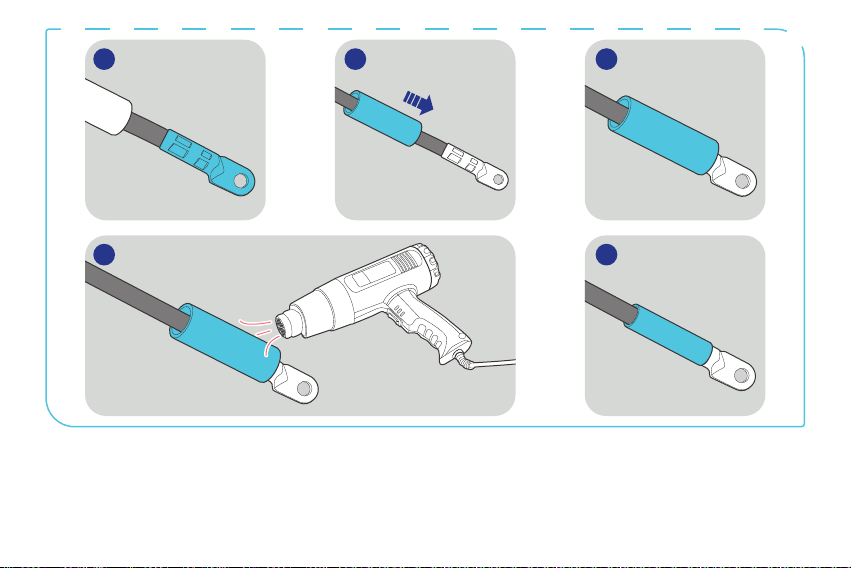
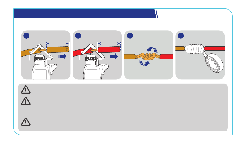
How to Install the 5/16 in Lugs (M8 Ring Terminals)?
You can connect your auxiliary battery and starter battery to the battery charger via the included
5/16 in Lugs (M8 Ring Terminals).
5
Heat
Shrink
Tubing
0.4 in
(10 mm)
Bare
Wires
1 2 3
4
— 8 —
6 7 8
9 10
— 9 —
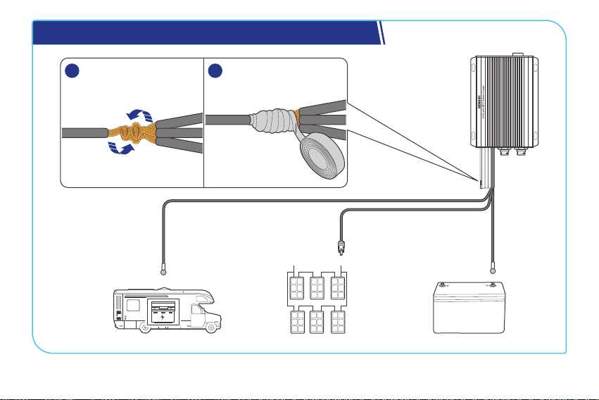
How to Install Cables on the Battery Charger?
The illustrations are based on the Positive Auxiliary Battery Cable.
0.4 in
(10 mm)
Battery
Charger
1
0.4 in
(10 mm)
Bare
Wires
2
4
3
Wear insulating gloves before wiring.
You are allowed to make connections using insulated conduit, junction boxes, or welding
methods. If the battery charger is installed outdoors, please ensure that the wiring
connections are waterproof.
After completing all the positive cable connections for relative devices, you can tape over
the negative common cable (black) in the cutoff areas.
— 10 —
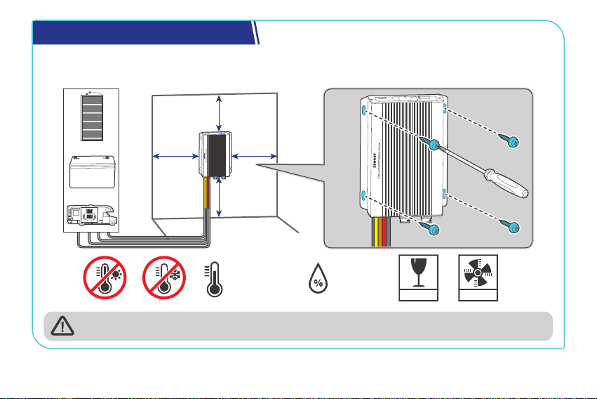
Step 1. Plan a Mounting Site
The battery charger requires adequate clearance for installation, wiring, and ventilation. The
minimum clearance is provided below.
5.91 in
(150 mm)
5.91 in
(150 mm)
5.91 in
(150 mm)
FRAGILE
VENTILATION
0% to 95%
-31°F to 176°F
-35°C to 80°C
Solar
Vehicle
Stage
Battery
5.91 in
(150 mm)
Solar
Vehicle
Stage
Battery
The battery charger should be installed on a flat surface protected from direct sunlight.
— 11 —
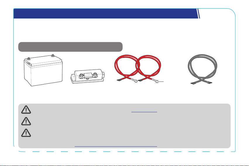
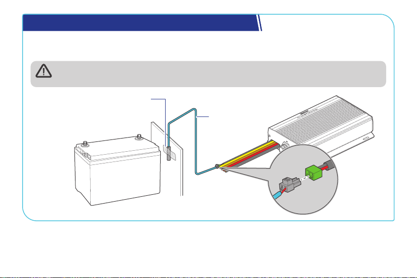
Step 2. Connect the Battery Charger to an Auxiliary Battery
The battery charger can only be connected to deep-cycle gel-sealed lead-acid batteries (GEL),
flooded lead-acid batteries (FLD), sealed lead-acid batteries (SLD/AGM), or lithium iron phosphate
batteries (LI).
Recommended Components & Accessories
*12V/24V Battery
(11V to 32V)
Bare Wire (6 AWG) × 1
*ANL Fuse
(60A) × 1
Battery Adapter Cables
(6 AWG) × 2
3/8 in
(M10)
+
-
Accessories marked with “*” are available on renogy.com.
For installation details, see the user manual of the battery in use.
To ensure optimal system performance, a 6 AWG cable should be no longer than 3 meters.
Choose higher gauge cables for longer distances. For details, see the user manual of the
battery charger at www.renogy.com/support/downloads.
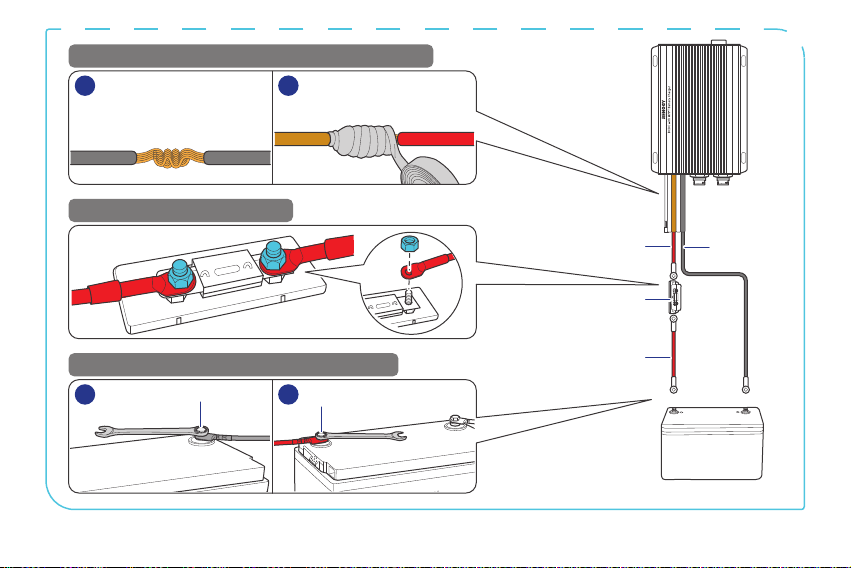
— 12 —
Battery
Adapter
Cable
Battery
Adapter
Cable
ANL Fuse (60A)
Bare Wire
-
+
1
2
12
-
Auxiliary Battery
++
-
-
STEP-1 Install cables on the battery charger
STEP-2 Install an ANL fuse
STEP-3 Install the cables on the battery
1
1 2
2
Negative
Common
Cable
Battery
Charger
Battery
Adapter
Cable
Bare
Wire
— 13 —
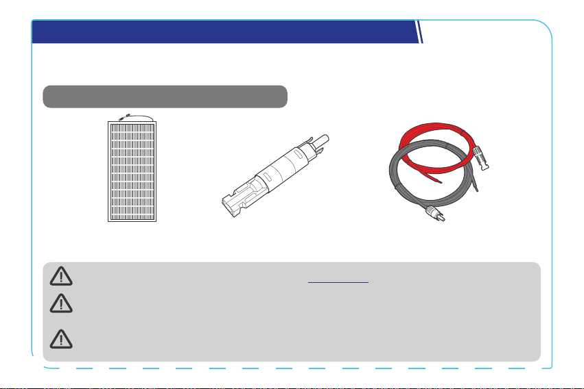
Step 3. Connect the Battery Charger to a Solar Panel
z
For 12V batteries, the maximum charging current from solar panels is 50A.
z
For 24V batteries, the maximum charging current from solar panels is 25A.
Recommended Components & Accessories
*Solar Panel Extension
Cables (4 AWG) × 2
*Solar Panel (s)
*Solar Panel Fuse
Accessories marked with “*” are available on renogy.com.
Connecting the battery charger to a solar panel exceeding 720W (≤50V) results in damage
to the battery charger.
The appropriate current rating for the solar panel fuse should be determined by
multiplying the total amperage of the solar panel array by 1.56.
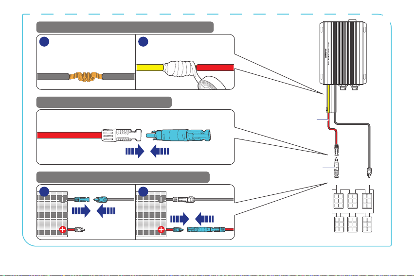
— 14 —
Solar Panel
Extension
Cables
Solar Panel (s)
+
-
STEP-1 Install cables on the battery charger
STEP-2 Install an solar panel fuse
STEP-3 Install the cables on the solar panel
1
1 2
2
Negative
Common
Cable
Battery
Charger
Solar Panel
Extension
Cable
Solar Panel Extension Cable Solar Panel Fuse
Solar Panel
Extension
Cable
Solar Panel Fuse
— 15 —
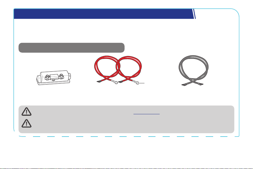
Step 4. Connect the Battery Charger to a Starter Battery
Before installing the charger, consult your vehicle’s user manual or contact the vehicle
manufacturer to ensure that the alternator power does not exceed 720W with the output current
within the range of 75A to 100A.
Recommended Components & Accessories
Bare Wire (4 AWG) × 1
*ANL Fuse
(100A) × 1
Battery Adapter Cables
(4 AWG) × 2
3/8 in
(M10)
Accessories marked with “*” are available on renogy.com.
The starter battery stops charging the auxiliary battery when the starter battery voltage
drops below 12.7V for 12V systems or 25.4V for 24V systems.
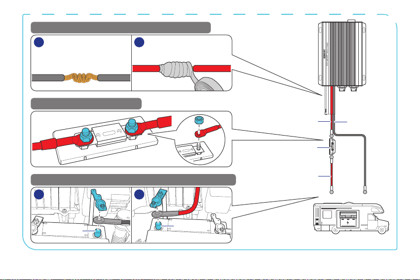
— 16 —
Battery
Adapter
Cable
Battery
Adapter
Cable
ANL Fuse (100A)
Bare Wire
Starter Battery
+
+
-
-
STEP-1 Install cables on the battery charger
STEP-2 Install an ANL fuse
STEP-3 Install the cables on the RV starter battery
1
1 2
2
Negative
Common
Cable
Battery
Charger
Battery
Adapter
Cable
Bare
Wire
— 17 —
Step 5. Tape over the Negative Common Cable
Starter Battery
-
1 2
Negative
Common
Cable
Auxiliary Battery
-
Solar Panel (s)
-
— 18 —
Step 6. Install a Battery Temperature Sensor
The temperature sensor measures the surrounding temperature of the battery and compensates
the floating charge voltage when the battery temperature is low.
Do not use the temperature sensor on a LiFePO4 (LFP) battery which comes with a
battery management system (BMS).
+
-
Mount the sensor securely
at a suitable location in
close proximity to the battery.
Battery
Temperature
Sensor
— 19 —
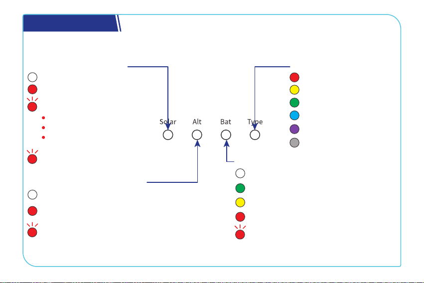
LED Indicators
The battery charger turns on automatically after power on with the LED indicators working in
accordance with the relative operating status.
Solar Charging Indicator
Solid:
O:
Not charging
MPPT charging
Slow flash :
2s: Boost charging
Fast flash (0.5s):
Equalization charging
Solid:
O:
Not charging
The alternator is charging the auxiliary
battery.
Flash:
The solar panel is charging the starter
battery.
Alternator Charging Indicator
Solid:
FLD
Solid:
GEL
Solid:
SLD/AGM
Solid:
12V LI
Solid:
24V LI
Solid:
User Mode
Solid:
O:
No battery detected
Full charge
Slow flash (2s):
Overdischarge warning
Solid:
Normal battery voltage
Solid:
Undervoltage warning
Fast flash (0.5s):
Overtemperature/
Overvoltage warning
Auxiliary Battery Indicator
Battery Type Indicator
One time: Float charging
Two times: Limited-current
charging
— 20 —
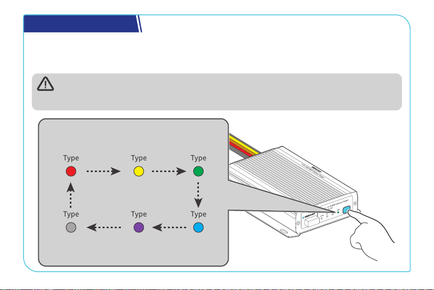
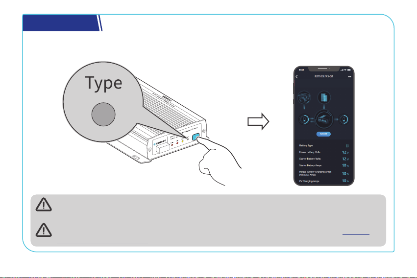
Set a Battery Type
Upon installing the battery charger, set a correct battery type by using the Battery Type Setting
Button. For non-lithium batteries, the battery charger can automatically detect their voltage (12V
or 24V).
It is essential to ensure that the battery type setting is configured correctly to avoid any
potential damage to the battery charger because any damage to the battery charger
resulting from an incorrect battery type setting voids the warranty.
FLD
Flooded Battery
GEL
Gel Battery
SLD/AGM
Sealed Lead
Acid Battery
User Mode
Custom Battery
24V LI
24V Lithium
Battery
12V LI
12V Lithium
Battery
— 21 —
USER Mode
Setting the battery type to User Mode allows you to customize your battery parameters. You can
modify the parameters in the DC Home app.
When customizing settings, consult the user manual provided by the battery
manufacturer. If necessary, contact the manufacturer for further assistance.
For detailed parameter settings, see the user manual of the battery charger at renogy.
com/support/downloads.
— 22 —
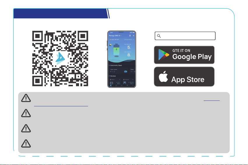
Monitor the Battery Charger
Download the DC Home app. Login to the app with your account.
DC Home App
Download on the
For CAN communication details, see the user manual of the battery charger at renogy.
com/support/downloads.
The version of the DC Home app might have been updated. Illustrations in the user
manual are for reference only. Follow the instructions based on the current app version.
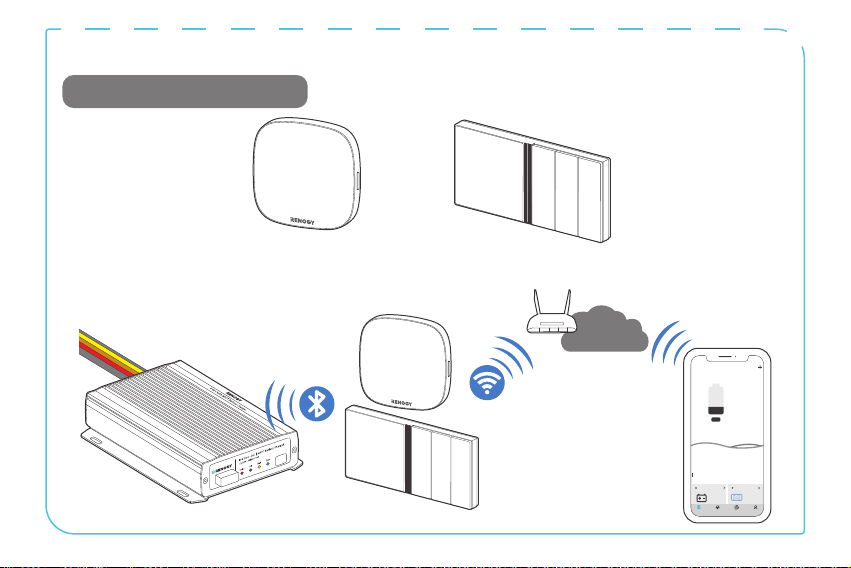
To ensure optimal system performance, keep the phone or RENOGY ONE within 10 feet (3
m) of the battery charger.
You can receive fault alarms on DC Home and Renogy ONE when the battery charger is
faulty. Please login to the DC Home app or Renogy ONE for troubleshooting details.
— 23 —
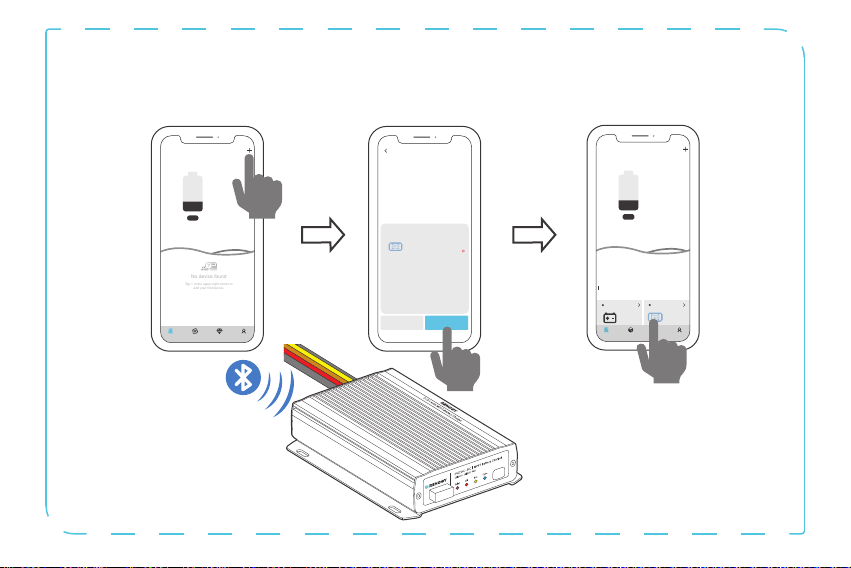
Short-Range Monitoring via DC Home App
Pair the battery charger with the DC Home app. Monitor and modify the parameters of the battery
charger via the app.
Cancel Confirm
RBT100LFPS-G1
DC-DC
Found Devices
HUB Mode
Searching for device
Please make sure:
1. Bluetooth on this phone/tablet is
turned on.
2. The device is running properly.
3. The device's Bluetooth is turned on.
Identifying device...
My Renogy
25%
A
Device
Devices
Battery
RBT12400LFPL-...
Controller
Scene Community Me
DC-DC
%
25
A
0
-
No device found
Tap + in the upper-right corner to
add your first device.
---
My Renogy
Time remaining
--
CommunityDevice Select Me
— 24 —
Wireless Long-Range Monitoring
Recommended Components.
*RENOGY ONE Core or Renogy ONE M1
Internet
My Renogy
25%
A
Device
Devices
Battery
RBT12400LFPL-...
Controller
Scene Community Me
DC-DC
%
25
A
0
-

— 25 —
Important Safety Instructions
█
General
z
Wear proper protective equipment and use insulated tools during installation and operation.
Do not wear jewelry or other metal objects when working on or around the battery charger.
z
Keep the battery charger out of the reach of children.
z
Do not dispose of the battery charger as household waste. Comply with local, state, and
federal laws and regulations and use recycling channels as required.
z
In case of fire, put out the fire with a FM-200 or CO₂ fire extinguisher.
z
Installing the battery charger improperly on a boat may cause damage to components of the
boat. Have the devices installed by a qualified electrician.
z
Do not expose the battery charger to flammable or harsh chemicals or vapors.
z
Clean the battery charger regularly.
z
Do not puncture, drop, crush, penetrate, shake, strike, or step on the battery charger.
z
Do not open, disassemble, repair, tamper with, or modify the battery charger.
z
Connect the negative prior to the positive terminal when connecting any device.
z
It is recommended that all cables should not exceed 10 meters because excessively long
cables result in a voltage drop.
z
The cable specifications listed in the quick guide account for critical, less than 3% voltage
drop and may not account for all configurations.

— 26 —
█
Battery Charger Safety
z
Install the battery charger on a vertical surface - protected from direct sunlight, high
temperatures, and water. Make sure there is good ventilation.
z
Keep the battery charger away from heating equipment.
z
Do not insert foreign objects into the battery charger.
z
Confirm the polarities of the devices before connection. A reverse polarity contact can result
in damage to the battery charger, thus voiding the warranty.
z
Do not touch the connector contacts while the battery charger is in operation.
z
Disconnect all connectors from the battery charger before maintenance or cleaning.
█
Battery Safety
z
Do not use batteries if there is any damage.
z
Do not touch the exposed electrolyte or powder if the battery is damaged.
z
Risk of explosion! Never install the battery charger in a sealed enclosure with flooded
batteries! Do not install the battery charger in a confined area where battery gases can
accumulate.
z
Prior to installing the battery charger, ensure all battery groups are installed properly.
█
Solar Panel Safety
z
Do not use the solar panel(s) if there is any damage.
z
Prior to connecting the battery charger to the solar panel(s), shade the solar panel(s).
z
Always connect the battery charger to the battery first before connecting it to the solar panel.
This prevents damage caused by open-circuit voltage from the solar panel.
— 27 —
Renogy Support
To discuss inaccuracies or omissions in this quick guide or user manual, visit or contact us at:
contentservice@renogy.com
Questionnaire Investigation
To explore more possibilities of solar systems, visit Renogy Learning Center at:
renogy.com/support/downloads
renogy.com/learning-center
— 28 —
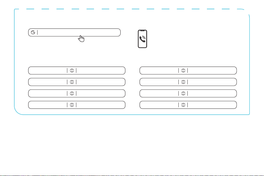
For technical questions about your product in the U.S., contact the Renogy technical support
team through:
1(909)2877111
For technical support outside the U.S., visit the local website below:
renogy.com/contact-us
Canada China
Australia
Japan
South Korea Germany
United Kingdom
Other Europe
ca.renogy.com www.renogy.cn
au.renogy.com renogy.jp
kr.renogy.com de.renogy.com
uk.renogy.com eu.renogy.com

— 29 —
FCC Statement
This device complies with Part 15 of the FCC Rules. Operation is subject to the following two
conditions:
(1) This device may not cause harmful interference.
(2) This device must accept any interference received, including interference that may cause
undesired operation.
Any Changes or modifications not expressly approved by the party responsible for compliance
could void the user’s authority to operate the equipment.
This equipment has been tested and found to comply with the limits for a Class B digital device,
pursuant to Part 15 of the FCC Rules. These limits are designed to provide reasonable protection
against harmful interference in a residential installation. This equipment generates, uses and can
radiate radio frequency energy and, if not installed and used in accordance with the instructions,
may cause harmful interference to radio communications. However, there is no guarantee that
interference will not occur in a particular installation. If this equipment does cause harmful
interference to radio or television reception, which can be determined by turning the equipment
off and on, the user is encouraged to try to correct the interference by one or more of the
following measures:
(1) Reorient or relocate the receiving antenna.
(2) Increase the separation between the equipment and receiver.
(3) Connect the equipment into an outlet on a circuit different from that to which the receiver is
connected.
(4) Consult the dealer or an experienced radio/TV technician for help.
— 30 —
FCC Radiation Exposure Statement
This equipment complies with FCC radiation exposure limits set forth for an uncontrolled
environment. This equipment should be installed and operated with minimum distance 20cm
between the radiator & your body.
Disclaimer
Renogy 12V/24V 50A IP67 Dual Input DC-DC On-Board with MPPT Battery Charger Quick Guide ©
2023 Renogy. All rights reserved.
RENOGY
and
are registered trademarks of Renogy.
z
All information in the quick guide is subject to copyright and other intellectual property
rights of Renogy and its licensors. The quick guide may not be modified, reproduced, or
copied, in whole or in part, without the prior written permissions of Renogy and its licensors.
z
The registered trademarks in the quick guide are the property of Renogy. The unauthorized
use of the trademarks is strictly prohibited.
z
Renogy ensures the accuracy, sufficiency, and the applicability of information in the quick
guide at the time of printing due to continual product improvements that may occur.

— 31 —
z
Renogy assumes no responsibility or liability for personal and property losses, whether directly
and indirectly, caused by the user’s failure to install and use the product in compliance with
the quick guide.
z
Renogy is not responsible or liable for any failure, damage, or injury resulting from repair
attempts by unqualified personnel, improper installation, and unsuitable operation.
z
The illustrations in the quick guide are for demonstration purposes only. Details may appear
slightly different depending on product revision and market region.
z
Renogy reserves the right to change the information in the quick guide without notice. For the
latest quick guide, visit renogy.com.
RENOGY.COM
Renogy reserves the right to change the contents of this quick guide without notice.
Renogy Power Plus allows you to stay in the loop with upcoming solar energy innovations, share
your experiences with your solar energy journey, and connect with like-minded people who are
changing the world in the Renogy Power Plus community.
@Renogy Solar @Renogy@renogyocial
Renogy Power
PLUS