VERSION A0
February 20, 2025
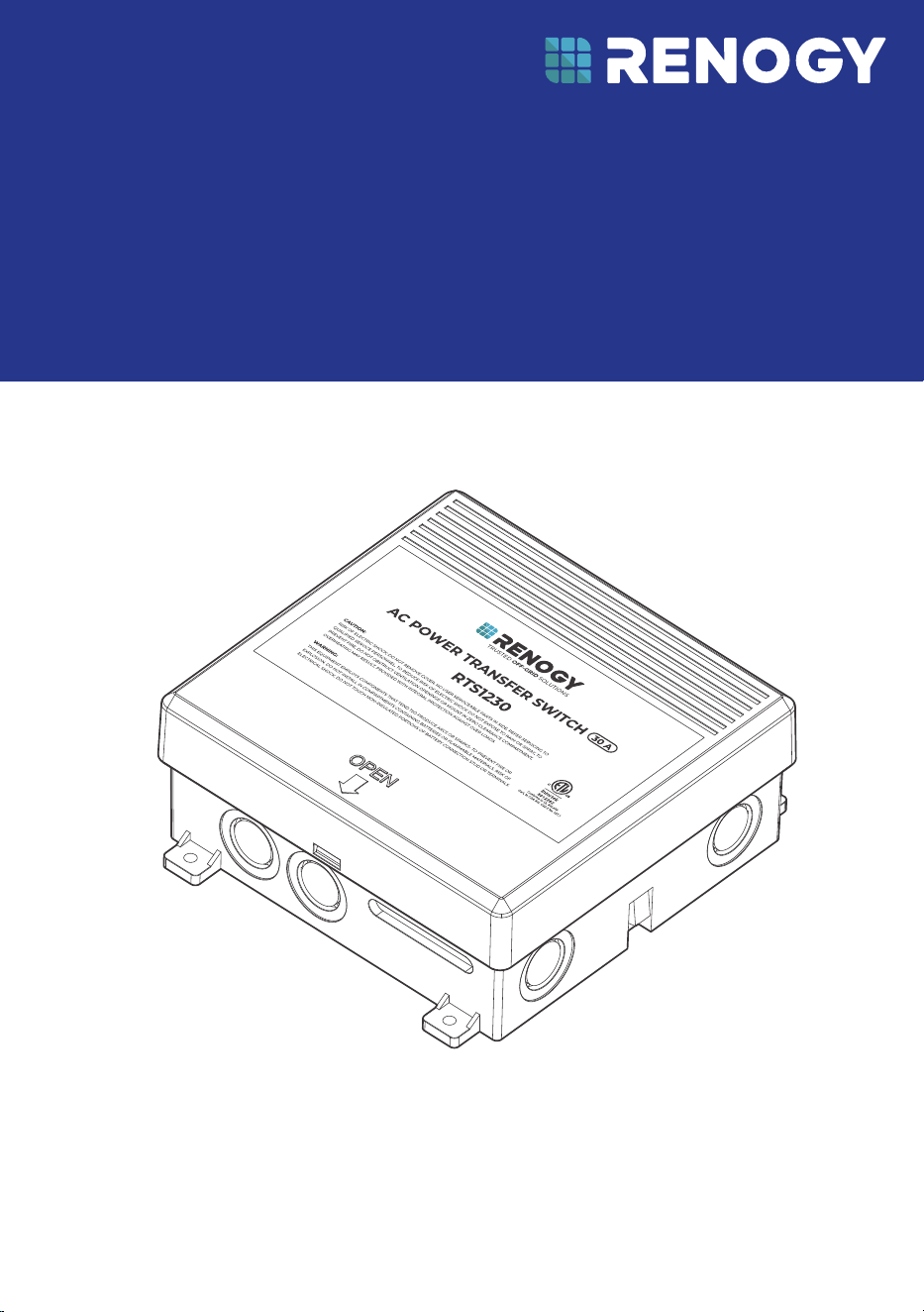
AC Power Transfer Switch
RENOGY
30A
RTS1230-G1
USER MANUAL
Before Getting Started
The user manual provides important operation and maintenance instructions for Renogy 30A AC
Power Transfer Switch (hereinafter referred to as transfer switch).
Read the user manual carefully before operation and save it for future reference. Failure to
observe the instructions or precautions in the user manual can result in electrical shock, serious
injury, or death, or can damage the battery, potentially rendering it inoperable.
z
Renogy ensures the accuracy, sufficiency, and the applicability of information in the user
manual at the time of printing due to continual product improvements that may occur.
z
Renogy assumes no responsibility or liability for personal and property losses, whether
directly and indirectly, caused by the user’s failure to install and use the product in
compliance with the user manual.
z
Renogy is not responsible or liable for any failure, damage, or injury resulting from repair
attempts by unqualified personnel, improper installation, or inappropriate operation.
z
The illustrations in the user manual are for demonstration purposes only. Details may appear
slightly different depending on product revision and market region.
z
Renogy reserves the right to change the information in the user manual without notice. For
the latest user manual, visit renogy.com.
Disclaimer
Renogy 30A AC Power Transfer Switch User Manual © 2025 Renogy. All rights reserved.
RENOGY
and
are registered trademarks of Renogy.
z
All information in the user manual is subject to copyright and other intellectual property
rights of Renogy and its licensors. The user manual may not be modified, reproduced, or
copied, in whole or in part, without the prior written permissions of Renogy and its licensors.
z
The registered trademarks in the user manual are the property of Renogy. The unauthorized
use of the trademarks is strictly prohibited.
Online Manual
User Manual

— 1 —
Symbols Used
The following symbols are used throughout the user manual to highlight important information.
WARNING: Indicates a potentially dangerous condition which could result in injury or death.
CAUTION: Indicates a critical procedure for safe and proper installation and operation.
NOTE: Indicates an important step or tip for optimal performance.
Risk of electric shock! This transfer switch operates with 120VAC and features multiple
inputs. To avoid electric shock, ensure all inputs are fully disconnected before performing
any work on the device.
Risk of fire or explosion! DO NOT mount or install this transfer switch in compartments
intended for storing batteries or flammable liquids. The transfer switch is not ignition-
protected and contains components that may produce arcs or sparks.
DO NOT install this transfer switch near appliances that generate heat or water, such as
water heaters, furnaces, or beneath refrigerators, to prevent damage and ensure safe
operation.
Ensure the transfer switch is protected from direct contact with water and debris to
maintain functionality and safety.
Avoid mounting the transfer switch in a zero-clearance compartment to prevent
overheating.
Use the provided knockouts for wiring to ensure safe installation. DO NOT drill into the
metal housing; debris or metal shavings may compromise the transfer switch’s operation.
Introduction
Renogy 30A AC Power Transfer Switch is an electrical device designed to work seamlessly with
battery inverters or inverter chargers to ensure an uninterrupted power supply. It delivers up
to 3000 RMS symmetrical amps and automatically switches between multiple power sources,
including the grid, vehicle alternators, home generators, and DC batteries. This device is ideal for
systems demanding high reliability and continuous power, making it particularly suitable for use
in recreational vehicles (RVs).
Key Features
z
Easy Wiring
Equipped with terminal connections for AC input and output, enabling straightforward and
efficient wiring.
z
Simple Operation
Fully automated operation eliminates the need for additional manual intervention, providing a
hassle-free experience.
z
Stable and Reliable
Rigorously tested for reliability, the transfer switch delivers consistent performance across
various scenarios, including use in vehicles, boats, off-grid homes, and more — even in
environments as cold as 113°F (-20°C)
SKU
Renogy 30A AC Power Transfer Switch RTS1230-G1
— 2 —
What’s In the Box?
VERSION A0
February 20, 2025
AC Power Transfer Switch
RENOGY
30A
RTS1230-G1
USER MANUAL
Renogy 30A AC Power Transfer Switch × 1 User Manual × 1
Make sure that the transfer switch is complete and free of any signs of damage.
Otherwise, contact Renogy dedicated customer service at https://www.renogy.com/
contact-us.
The accessories and product manual listed are crucial for the installation, excluding
warranty information and any additional items. Please note that the package contents
may vary depending on the specific product model.
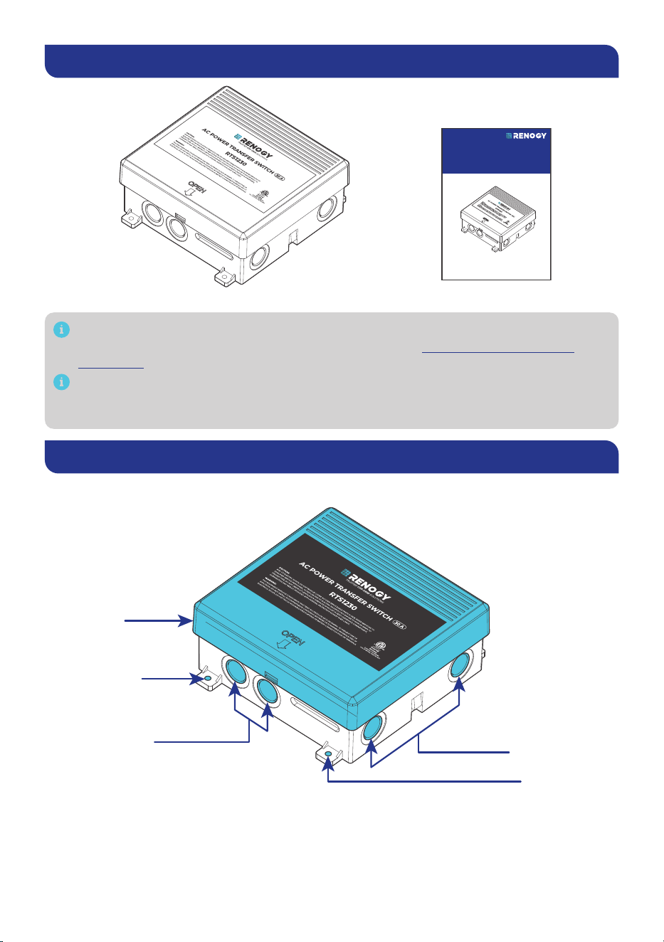
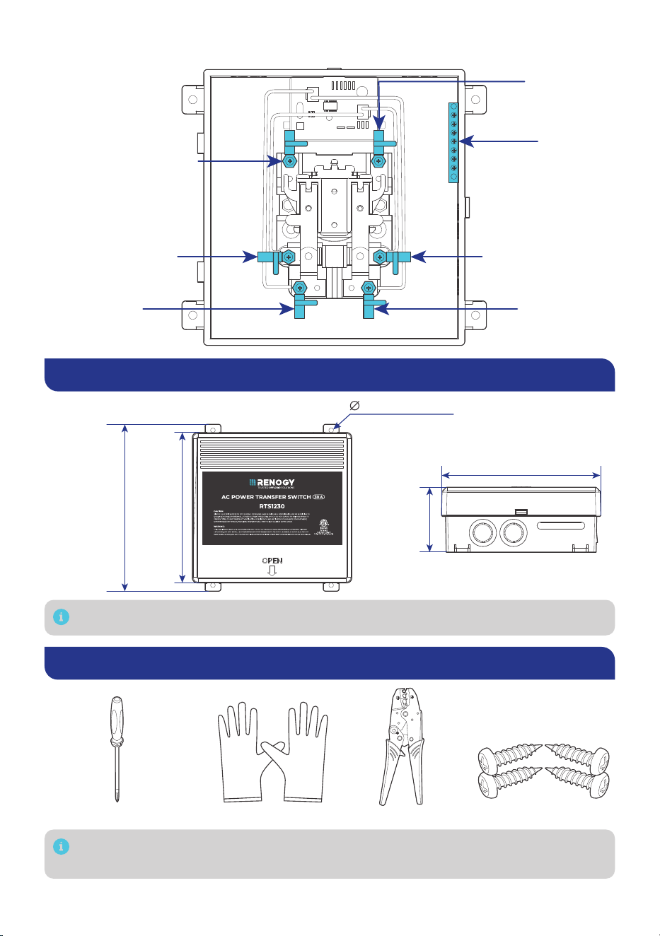
Get to Know the 30A AC Power Transfer Switch
Exterior View
Cable Knockouts
Cable Knockouts
Metal Cover
Mounting Hole
Mounting Hole
— 3 —
Interior View
CONTROLPANEL (L)
GENERATOR (L)
GENERATOR (N)
POWER CORD (N) POWER CORD (L)
CONTROLPANEL (N)
Generator Terminal N
Grid Terminal N
Ground Bar
Generator Terminal L
Grid Terminal L
Control Panel
Terminal L
Control Panel Terminal N
Dimensions
6.97 in
(177 mm)
7.73 in
(196.4 mm)
3.02 in
(76.6 mm)
0.21 in (5.3 mm)
7.38 in (187.5 mm)
Dimension tolerance: ±0.2 in (0.5 mm)
Required Tools & Accessories
Insulating GlovesPhillips Screwdriver (#2)
Wire Crimper Self-tapping Screws x 4
ST5 mm
Prior to installing the transfer switch, prepare the recommended tools, components, and
accessories.
— 4 —
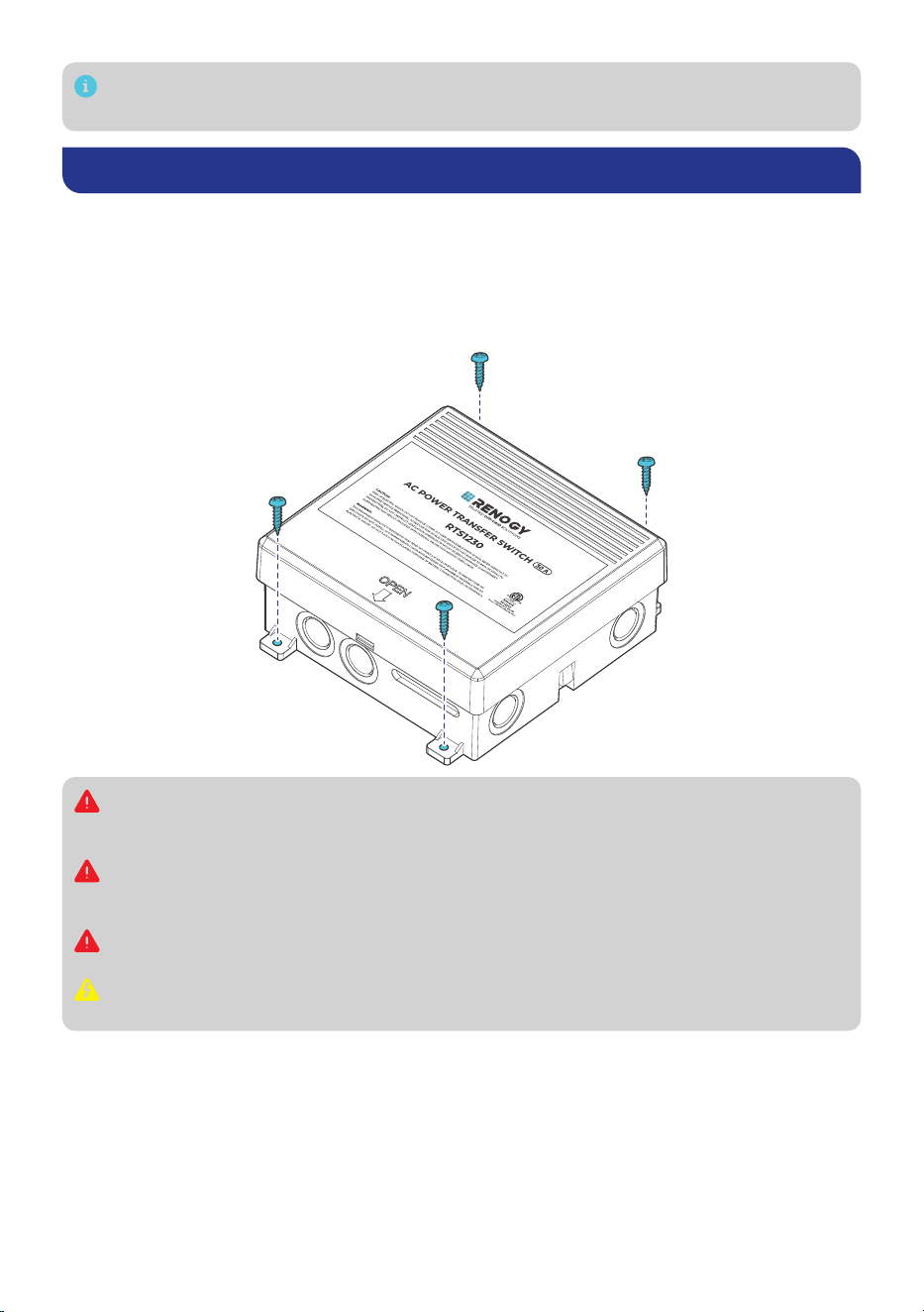
Choose proper mounting screws specific to your installation site. This manual takes self-
tapping screws for wooden walls as an example.
Installation
Step 1. Mounting
For optimal system performance, it is recommended to install the transfer switch in a clean, cool,
and dry location, free from any accumulation of water, oil, or dirt. Accumulation of such materials
on the transfer switch can lead to current leakage and even short-circuiting. Ensure that all
cables are sufficiently long to connect the transfer switch to related devices, such as the service
panel, inverter, and grid, without straining the connections.
Risk of fire or explosion! DO NOT mount or install this transfer switch in compartments
intended for storing batteries or flammable liquids. The transfer switch is not ignition-
protected and contains components that may produce arcs or sparks.
DO NOT install this transfer switch near appliances that generate heat or water, such as
water heaters, furnaces, or beneath refrigerators, to prevent damage and ensure safe
operation.
Ensure the transfer switch is protected from direct contact with water and debris to
maintain functionality and safety.
Avoid mounting the transfer switch in a zero-clearance compartment to prevent
overheating.
— 5 —
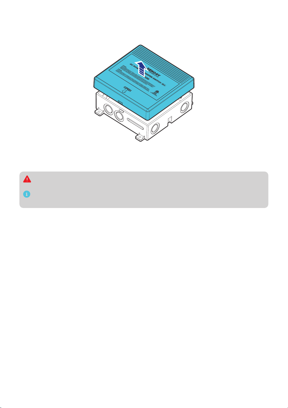
Step 2: Remove the Cover
Pry open the latch and remove the cover according to the labeled position (OPEN). Reinstall the
cover after complete wiring.
Step 3: Wiring
This section discusses wiring instructions for both power supply and ground terminals on the
transfer switch.
Risk of electric shock! Prior to wiring the transfer switch, wear insulating gloves, and power
off all power supplies including the grid, a generator/an alternator, and an inverter.
Remove cable knockout covers before wiring. Pass cables through the cable knockouts and
connect them to the terminals on the transfer switch.
█
Power Supply Terminals
The power supply terminals, including the Control Panel, Generator, and Grid Terminals, are
designed for ring terminal connections. Follow the steps below to wire a power supply terminal.
Step 1: Remove the ring connector from a power supply terminal via a Phillips screwdriver (#2).
Step 2: Size a proper cable based on the actual operating current. The ring terminals support wire
sizes from 14 AWG to 6 AWG.
Step 3: Strip the wire insulation of the cable according to the depth of the ring connector using a
wire crimper. Insert the stripped cable into the ring connector and crimp it securely with
the crimper.
Step 4: Install the ring connector back to the power supply terminal by using a Phillips screwdriver
(#2).
█
Ground Terminals
The ground terminals are equipped with cable retainers. Follow the steps below to wire a ground
terminal.
Step 1: Open a cable retainer by turning the cable retainer screw counterclockwise via a Phillips
screwdriver (#2).
Step 2: Size a proper cable based on the actual operating current. The ring terminals support wire
sizes from 14 AWG to 6 AWG.
Step 3: Strip the wire insulation of the cable according to the depth of the cable retainer using
a wire crimper. Insert the stripped cable into the retainer and crimp it securely with the
crimper.
— 6 —
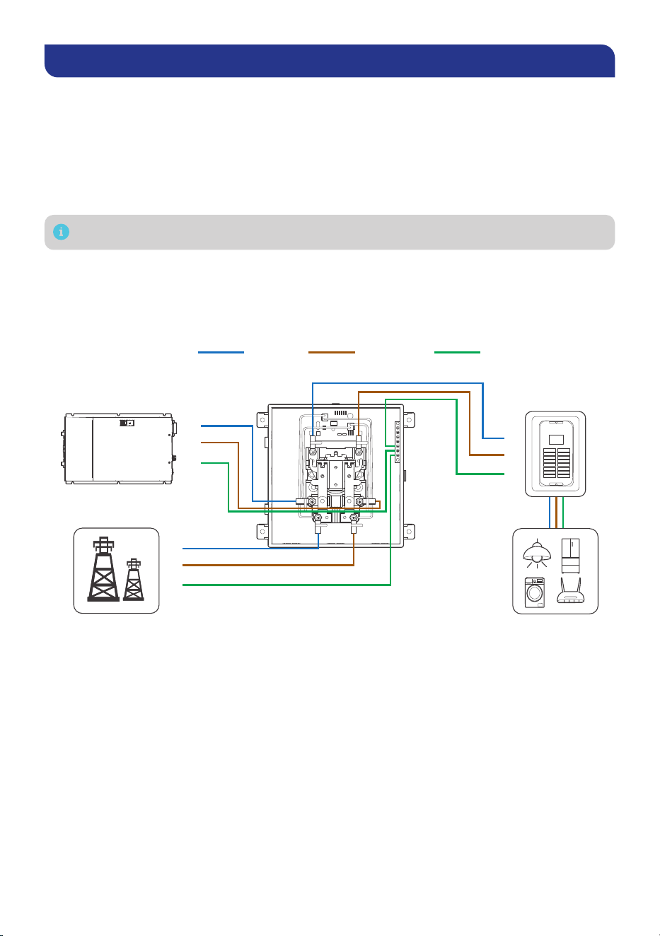
Working Logic
In general, the transfer switch allows switching between the grid, an inverter, and a generator/
alternator as power sources. The grid power remains available (pass-through) when using the
transfer switch. When grid power is available, the transfer switch automatically connects to the
control panel terminals.
If operating with an onboard vehicle alternators, starting the alternator triggers a 20 to 30-second
delay before power transfers from grid power to the alternator, allowing the alternator voltage to
stabilize. Once the alternator stops, the transfer switch immediately and automatically reconnects
to grid power.
The transfer switch works seamlessly with 120V AC home generators.
This section outlines three wiring configurations tailored to these source options.
█
Switching Between the Grid and an Inverter
When both the grid and an inverter are connected to the transfer switch, the switch will prioritize
grid power to supply loads. In the event of a grid power failure, the inverter will automatically take
over and supply power to the loads.
CONTROLPANEL (L)
GENERATOR (L)
GENERATOR (N)
POWER CORD (N) POWER CORD (L)
CONTROLPANEL (N)
Grid Power
L
N
PE
L
N
PE
L
N
PE
AC Loads
AC Load
Sub-panel
Inverter
(AC Output)
Neutral Live Ground
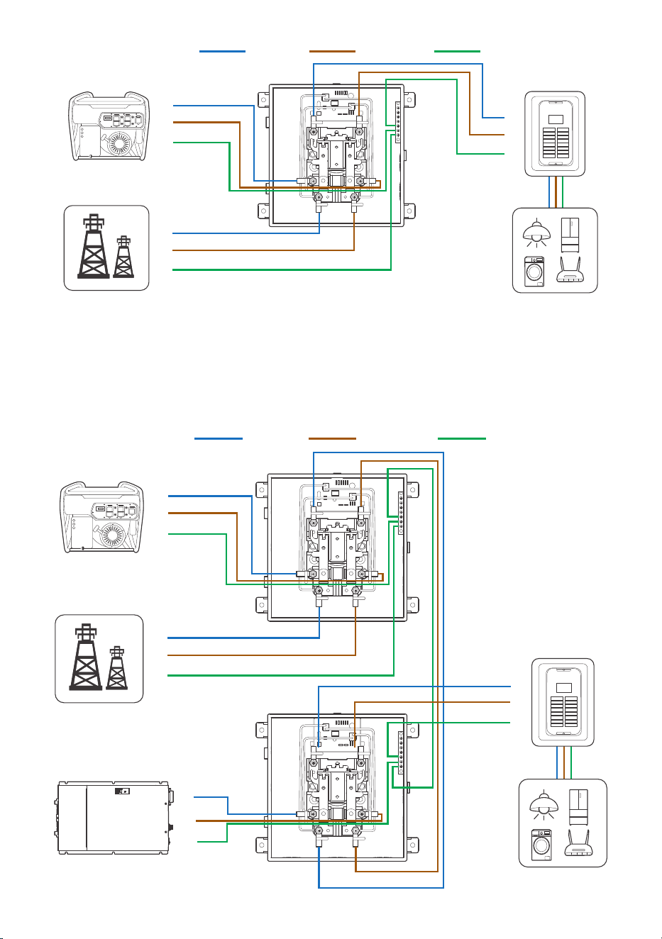
█
Switching Between the Grid and a Generator/an Alternator
When both the grid and a generator/an alternator are connected to the transfer switch, the
switch will prioritize grid power to supply loads. In the event of a grid power failure, the generator/
alternator will automatically take over and supply power to the loads.
— 7 —
CONTROLPANEL (L)
GENERATOR (L)
GENERATOR (N)
POWER CORD (N) POWER CORD (L)
CONTROLPANEL (N)
L
N
PE
L
N
PE
L
N
PE
AC Loads
AC Load
Sub-panel
Neutral Live Ground
Grid Power
Generator/
Alternator
█
Switching Between the Grid, a Generator/an Alternator, and an Inverter
The transfer switch enables seamless switching between the grid, a generator/an alternator,
and an inverter when two transfer switches are installed in a system. The first transfer switch
connects the grid and a generator/an alternator as two AC power sources, while the second
transfer switch links the first transfer switch to the inverter. The system prioritizes grid power
supply. When grid power is insufficient, the generator/alternator is selected as the power source.
If the generator/alternator shuts down, the inverter supplies power.
CONTROLPANEL (L)
GENERATOR (L)
GENERATOR (N)
POWER CORD (N) POWER CORD (L)
CONTROLPANEL (N)
CONTROLPANEL (L)
GENERATOR (L)
GENERATOR (N)
POWER CORD (N) POWER CORD (L)
CONTROLPANEL (N)
L
N
PE
L
N
PE
AC Loads
Grid Power
Generator/
Alternator
L
N
PE
AC Loads
AC Load
Sub-panel
Neutral Live Ground
L
N
PE
Inverter
(AC Output)

— 8 —
Specifications
Model (SKU) RTS1230-G1
Input Voltage and Frequency 120V AC, 60Hz
Input Current 30A
Output Voltage and Frequency 120V AC, 60Hz
Output Current 30A
Grid Power Input Supported
Dimensions 7.73 x 7.38 x 3.02 in / 196.4 x 187.5 x 76.6 mm
Weight 3 lbs / 1.36 kg
Knockout Quantity 10
Knockout Dimensions 2 x 7/8 in & 1 x 1.0 in (2 x 22.2 mm & 1 x 25.4 mm)
Transfer Delay 20s to 30s
Bypass Function Supported
Warranty 2 years
Certification ETL
Maintenance
Please perform regular inspections following the steps below:
z
Examine the external appearance of the transfer switch. The housing and terminals of the
transfer switch shall be clean, dry, and free of corrosion.
z
Check transfer switch cables and connections. Replace any damaged cables and tighten any
loose connections.
In certain application scenarios, corrosion may occur around the terminals. Corrosion
can cause increased resistance and poor contact. It is recommended to regularly apply
insulation grease to each terminal. Insulation grease can form a moisture-resistant seal
and protect the terminals from corrosion.
Important Safety Instructions
The manufacturer accepts no liability for any damage caused by:
z
Force majeure including fire, typhoon, flood, earthquake, war, and terrorism.
z
Intentional or accidental misuse, abuse, neglect or improper maintenance, and use under
abnormal conditions.
z
Improper installation, improper operation, and malfunction of a peripheral device.
z
Contamination with hazardous substances or radiation.
z
Alterations to the product without express written consent from the manufacturer.
— 9 —
z
Wear proper protective equipment and use insulated tools during installation and operation.
Do not wear jewelry or other metal objects when working on or around the transfer switch.
z
Keep the transfer switch out of the reach of children.
z
Do not dispose of the transfer switch as household waste. Comply with local, state, and
federal laws and regulations and use recycling channels as required.
z
In case of fire, put out the fire with a FM-200 or CO2 fire extinguisher.
z
Do not expose the transfer switch to flammable or harsh chemicals or vapors.
z
Clean the transfer switch regularly. Before cleaning, turn off all power sources and ensure
the transfer switch is completely dry before restoring power. Do not clean the interior of the
transfer switch.
Renogy Support
To discuss inaccuracies or omissions in this quick guide or user manual, visit or contact us at:
renogy.com/support/downloads
contentservice@renogy.com
Questionnaire Investigation
To explore more possibilities of solar systems, visit Renogy Learning Center at:
renogy.com/learning-center
For technical questions about your product in the U.S., contact the Renogy technical support
team through:
renogy.com/contact-us
1(909)2877111
For technical support outside the U.S., visit the local website below:
Canada ca.renogy.com China www.renogy.cn
Australia au.renogy.com Japan jp.renogy.com
Other Europe eu.renogy.com Germany de.renogy.com
United Kingdom
uk.renogy.com

RENOGY.COM
Renogy aims to empower people around the world through education and distribution of
DIY-friendly renewable energy solutions.
Renogy Power Plus allows you to stay in the loop with upcoming solar energy innovations,
share your experiences with your solar energy journey, and connect with like-minded
people who are changing the world in the Renogy Power Plus community.
We intend to be a driving force for sustainable living and energy independence.
In support of this eort, our range of solar products makes it possible for you to minimize
your carbon footprint by reducing the need for grid power.
Renogy Empowered
Live Sustainably with Renogy
Did you know? In a given month, a 1 kW solar energy system will...
Save 170 pounds of coal from being burned
Save 300 pounds of CO2 from being released into the atmosphere
Save 105 gallons of water from being consumed
@Renogy Solar @Renogy@renogyocial
Renogy Power
PLUS
Renogy reserves the right to change the contents of this manual without notice.
eVatmaster Consulting GmbH
Frankfurt am Main, Germany
Battinastr. 30, 60325
EC REP
Manufacturer: RENOGY New Energy Co.,Ltd
Address: No.66, East Ningbo Road Room 624-625 Taicang German
Overseas Students Pioneer Park JiangSu 215000 CN
EVATOST CONSULTING LTD
London, United Kingdom, EC2R 8AY
Office 101 32 Threadneedle Street,
UK REP
Manufacturer: RENOGY New Energy Co.,Ltd
Address: No.66, East Ningbo Road Room 624-625 Taicang German
Overseas Students Pioneer Park JiangSu 215000 CN
5012262