
To download the latest version of Quick Start
Guide, multilingual user manual, software, or
driver, etc., please visit Lumens
https://www.MyLumens.com/support
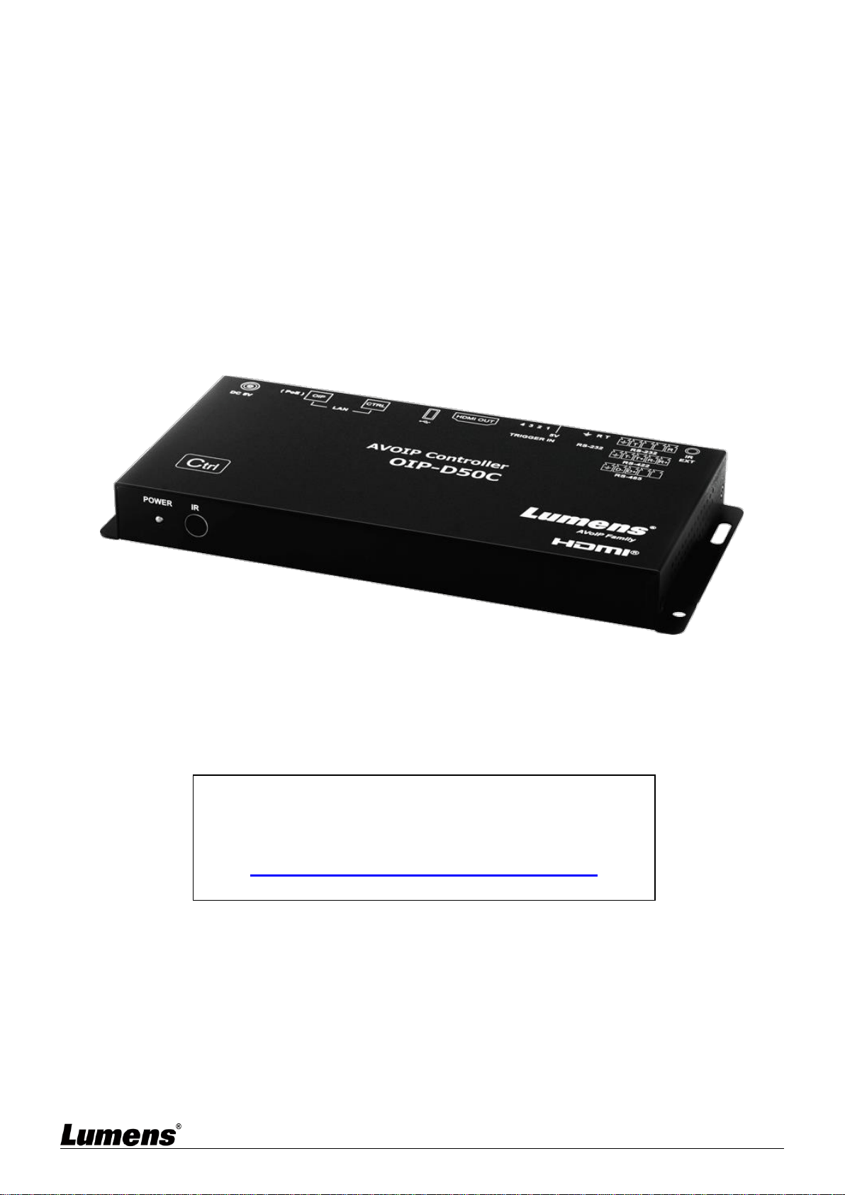
OIP-D50C
AVoIP Controller
User Manual - English
[Important]

1
Table of Contents
Chapter 1 Package Contents ................................................................... 2
Chapter 2 Instruction before installation ................................................ 3
2.1 Selecting Switch ............................................................................................... 3
2.2 Bandwidth Calculation .................................................................................... 3
Chapter 3 Product Overview .................................................................... 4
3.1 System Requirements ..................................................................................... 4
3.2 I/O functions Introduction ............................................................................. 4
3.3 Remote Control ................................................................................................ 5
3.4 IR Pin Assignment ............................................................................................ 5
3.5 RS-232 Pin and Default Setting .................................................................... 5
Chapter 4 Installation and Connections ................................................. 6
4.1 Connection diagram ........................................................................................ 6
4.2 Connection Setting .......................................................................................... 6
Chapter 5 Start Using ............................................................................... 7
5.1 Switch Setting ................................................................................................... 7
Chapter 6 WebGUI Control ...................................................................... 8
6.1 WebGUI Control Descriptions ...................................................................... 8
6.2 WebGUI Control Menu Descriptions .......................................................... 9
Chapter 7 Troubleshooting .................................................................... 22
Chapter 8 Safety Instructions ................................................................ 23
Copyright Information ............................................................................... 24
2
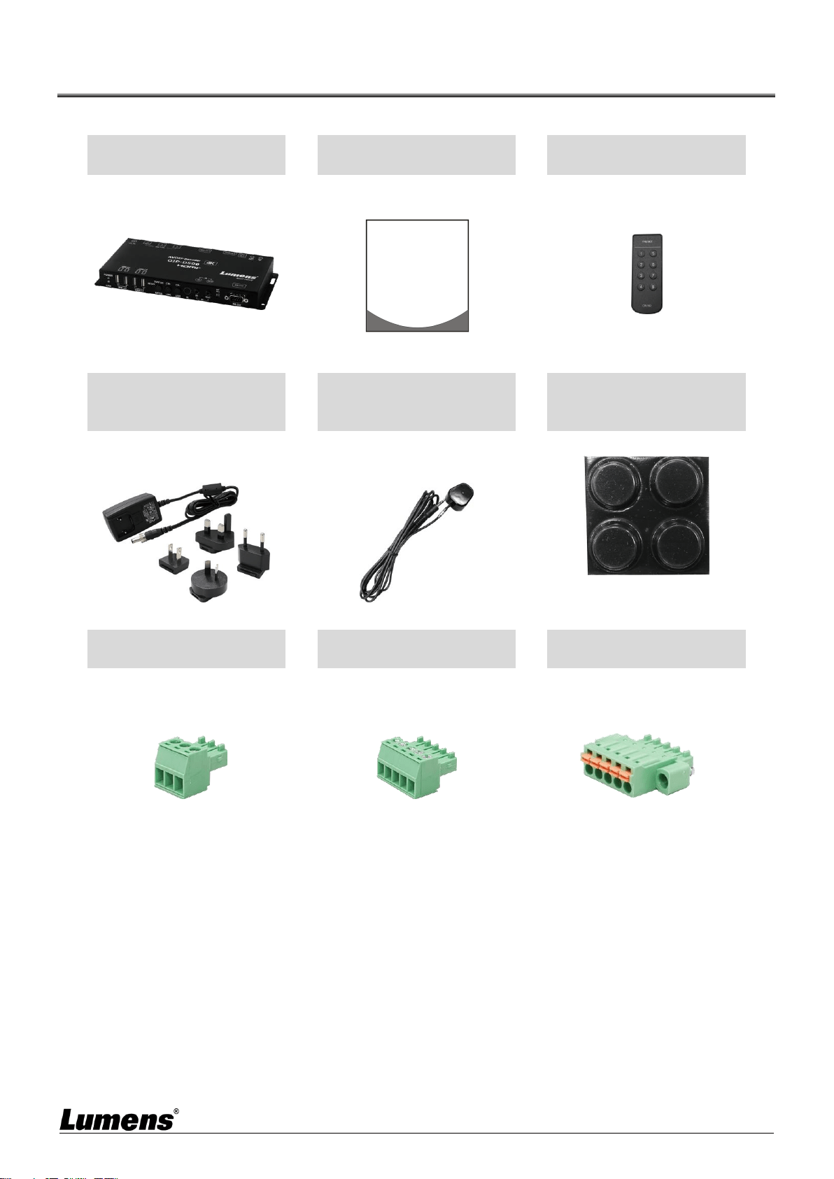
Chapter 1 Package Contents
OIP-D50C Controller
Instruction for
installation
Remote Control
5V/2.6A Power supply
(including a
multinational adapter)
3.5 mm to infrared
extender
Foot mats
(A set of four)
Terminal block
(90° 3pin)
Terminal block
(90° 5pin)
Terminal block
(180° 5pin)
x2
Quick Installation Guide
3
Chapter 2 Instruction before installation
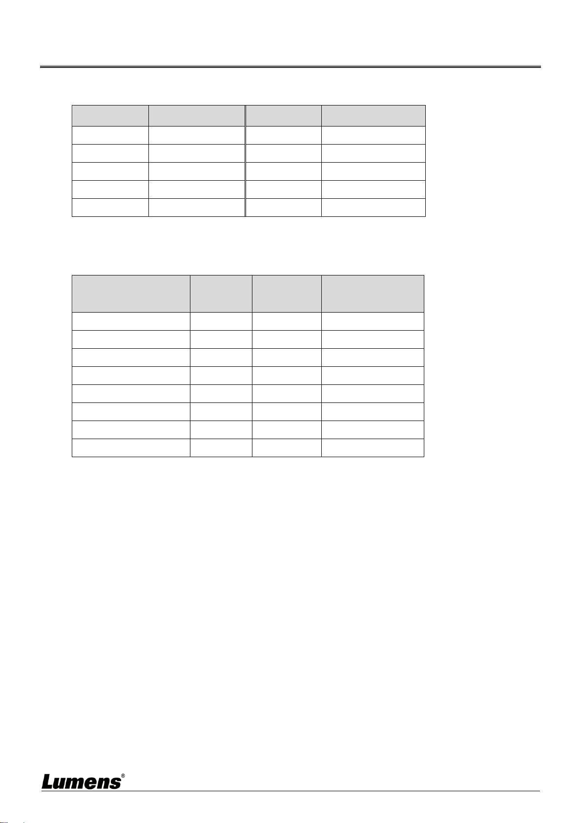
2.1 Selecting Switch
Recommended Brand/Model
Brand
Model
Brand
Model
NETGEAR
S3300 Series
ZyXEL
GS1920
NETGEAR
M4300 Series
ZyXEL
GS2210
D-Link
DGS-1510
ZyXEL
XS3700
Cisco
Catalyst 2960-X
Dell
PowerConnect 5524
EtherWAN
EX26262F
Dell
PowerConnect 2816
2.2 Bandwidth Calculation
The table below summarizes the network bandwidth required for setting resolutions before
installation as a reference
Resolution
Image
Quality
Settings
Maximum
Frame Rate
Average Network
Bandwidth (Mbps)
3840*2160 (2160p30)
Auto
30
218 (146~268)
1920*1080 (1080p)
Auto
60
133 (80~210)
1280*720 (720p)
Auto
60
147 (112~177)
1600*1200 (UXGA)
Auto
60
81 (57~105)
1280*1024 (SXGA)
Auto
60
113 (79~150)
1024*768 (XGA)
Auto
60
81 (72~120)
800*600 (SVGA)
Auto
60
66 (49~82)
640*480 (VGA)
Auto
60
43 (29~56)
4
Chapter 3 Product Overview
3.1 System Requirements
An effective network connection provided by a switch or router, used to connect this product and a
compatible VoIP extender (including encoder and decoder).
An HDMI audio and video equipment, such as a HD TV or screen.
3.2 I/O functions Introduction
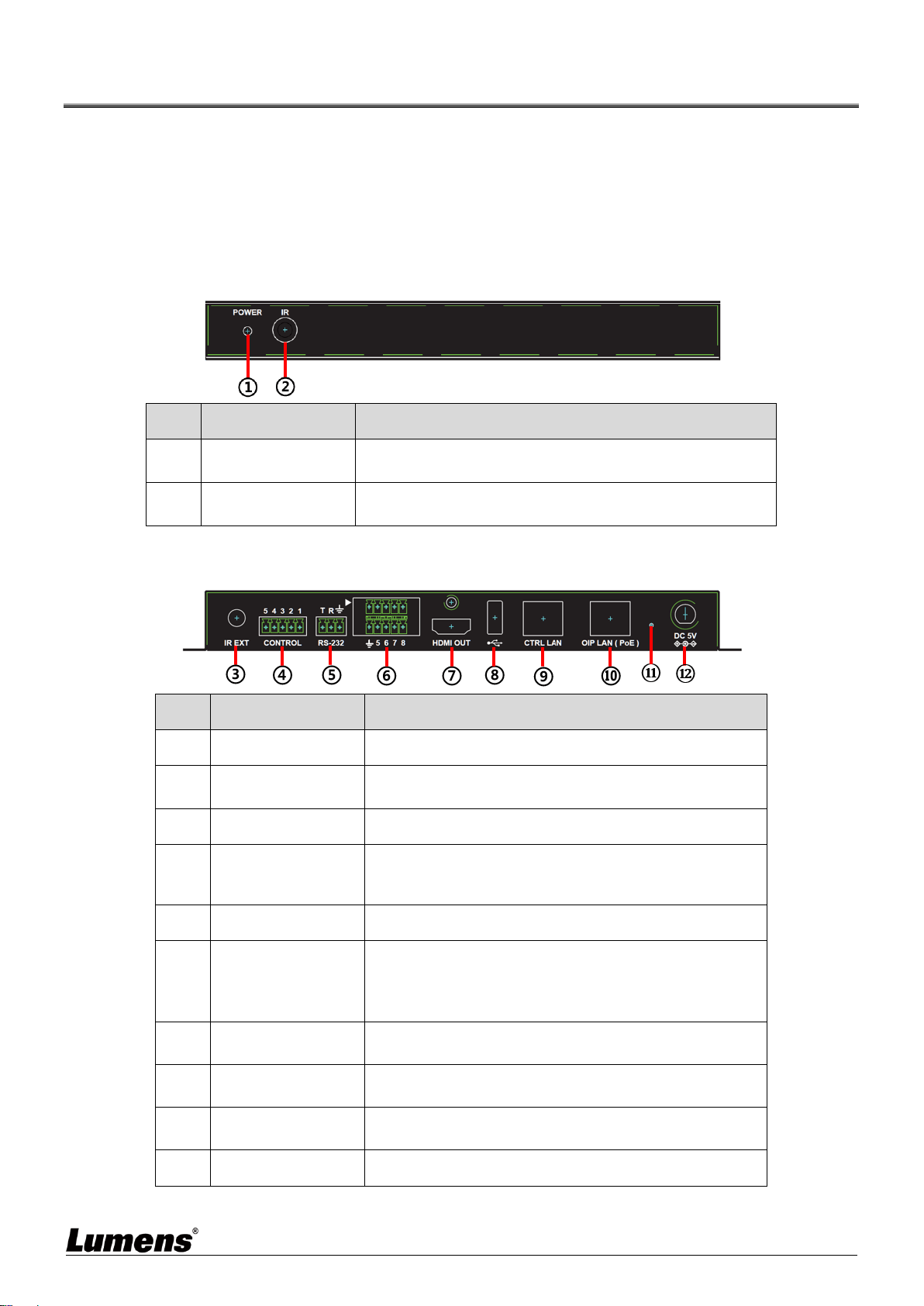
3.2.1 Front panel
NO.
Item
Function Descriptions
①
Power indicator
When this light is on, the product is turned on and
connected to the power supply.
②
IR receive window
It only receives the IR signals from the remote control of
this product.
3.2.2 Rear panel
NO.
Item
Function Descriptions
③
IR input port
Connect an IR extender to extend IR to remote devices.
④
RS-232/RS-422/RS
-485 output port
Not supported yet, it is expected to be activated through
firmware update in the future.
⑤
RS-232 input port
This product can be operated via RS-232.
⑥
Contactor input port
Connect to other devices with contactor switch
functions, such as window alarms and door switches. It
can receive up to 8 contactor signals.
⑦
HDMI output port
It can connect to an HDMI display.
⑧
USB port
It can connect a USB keyboard and mouse to operate
the WebGUI control page.
<Remark> Please connect the USB control device
before turning on this product.
⑨
CTRL network port
A computer can operate this product via a network
switch connect device.
⑩
OIP network port
(PoE)
It can connect to a control encoder and decoder.
⑪
Reset-to-default
button
Hold this button for 3 seconds to restart the device and
restore the factory settings.
⑫
Power connector
Plug in the 5V DC power adapter to supply power.

5
3.3 Remote Control
Preset locations 1 ~ 8: Press any key to start the corresponding preset location of that
number.
3.4 IR Pin Assignment
3.5 RS-232 Pin and Default Setting
Default Setting of the Serial Port
Baud Rate
19200
Data Bit
8
Parity Bit
N
Stop Bit
1
Flow Control
N
3-pin Terminal Block
GND
RxD
TxD
IR Extender
IR
Electricity
Ground
6
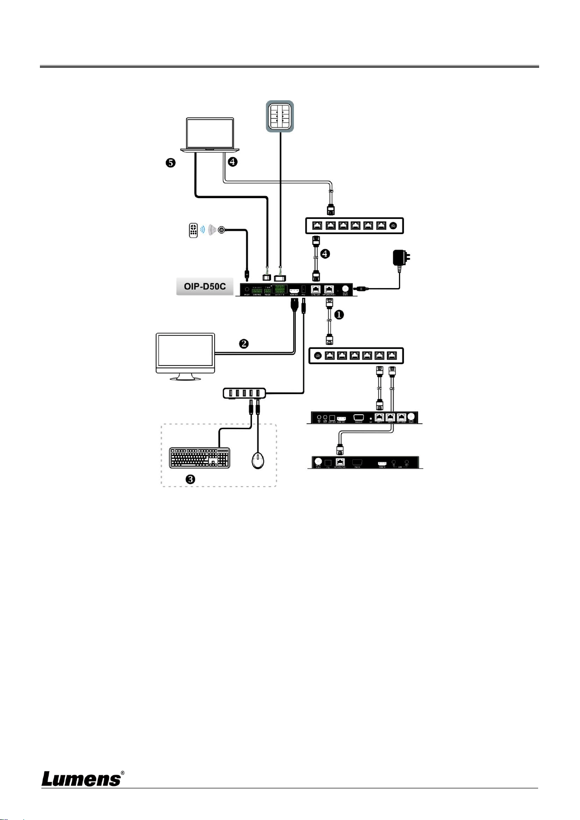
Chapter 4 Installation and Connections
4.1 Connection diagram
4.2 Connection Setting
This product needs to be equipped with a encoder and decoder at the same time. After the
encoder and decoder are connected, connecting to this product can manage multiple encoders
and decoders through the WebGUI control page.
① Connect the network switch of the same domain as the encoder and decoder to the OIP
network port, so that all OIP devices are in the same local area network.
② Connecting to a HDMI display can check the device status message and access the
WebGUI control page without computer.
③ Connect to USB keyboard and mouse.
After completing the above steps, you can use the keyboard and mouse to operate the
WebGUI control page for operations and settings. You can also follow the steps below to
control this product through computer:
④ Connect the CTRL network port to the network switch of the same domain as the computer,
so that the D50C controller and the computer are in the same local area network. Enter the
IP address of the controller in the web browser to operate and control the product on the
web page.
⑤ Use a 3-pin terminal block to DE-9 terminal cable to connect to a desktop, notebook, or
other serial main control devices, to perform operation through RS-232.
IR
Remote Control
Power Supply
LAN
Control keyboard with
a contactor
LAN
Computers with serial
ports or network ports
RS-232 input
Or
Special Local Area
Network Connection
Network Switch
LAN
Special VoIP Network
Connection
Network Switch
LAN
Contactor
input
HDMI output
VoIP Decoder
VoIP Encoder
LAN
USB hub
HDTV
Keyboard/Mouse
IR input

7
Chapter 5 Start Using
5.1 Switch Setting
Notes
VoIP transmission will consume a lot of bandwidth (high resolutions), and it needs to be paired with
a Gigabit network switch that supports Jumbo Frame and IGMP (Internet Group Management
Protocol) Snooping. It is strongly recommended to be equipped with a switch which includes VLAN
(Virtual Local Area Network) professional network management.
Most consumer-grade routers cannot handle the high traffic flow generated by multicast, so it is not
recommended to directly use the router as your network switch. It is strongly recommended to avoid
mixing your commonly used network traffic with VoIP streaming flow. VoIP streaming flow should at
least use a separate subnet.
Setting Suggestions
Please set Port Frame Size (Jumbo Frame) to 8000.
Please set IGMP Snooping and relevant settings (Port, VLAN, Fast Leave, Querier) to [Enable].
8
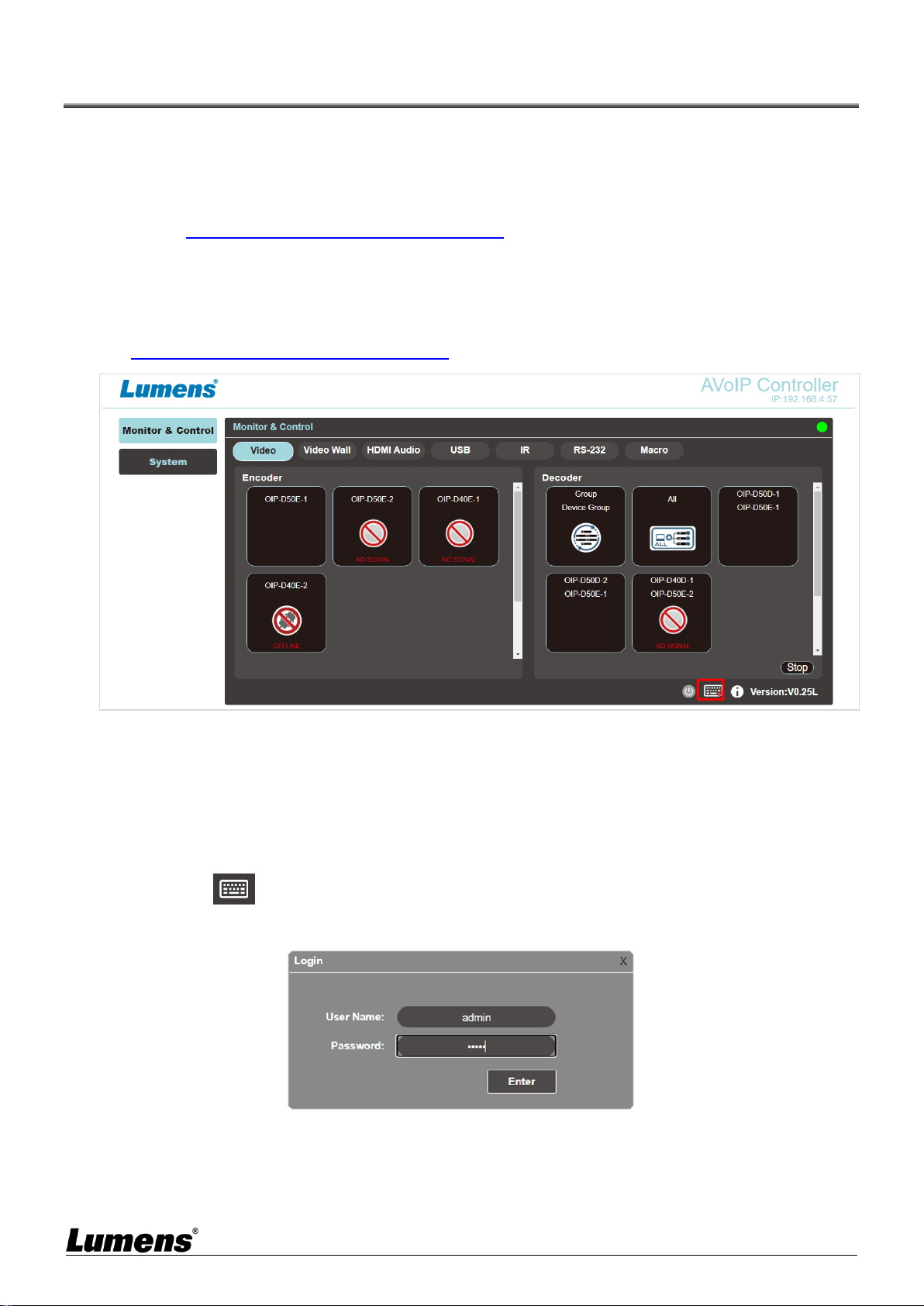
Chapter 6 WebGUI Control
6.1 WebGUI Control Descriptions
6.1.1 Control by Connecting a Display
Connect the display to the HDMI output port as well as the keyboard and mouse to the USB port to
see the unlogged WebGUI control page as shown in the figure below. For detailed menu descriptions,
please see 6.2 WebGUI Control Menu Descriptions.
6.1.2 Control via a Web Browser
Open a web browser on the computer and enter the IP address of the CTRL LAN port to see the
unlogged WebGUI control page as shown in the figure below. For detailed menu descriptions, please
see 6.2 WebGUI Control Menu Descriptions.
Even if the user has not logged in, the user can still operate some tabs (Monitor & Control, System).
On the one hand, it allows users to change the existing I/O settings or preset I/O settings at any time.
It also protects other sensitive and critical settings and configuration for you. To log in to the WebGUI
control page, please go to the System tab and click the login button. The default user name and
password are both “admin”. If you control the device with a display but without a keyboard, click the
keyboard icon in the lower right corner to open the keyboard and type in the user name and
password.
<Remark> If you are not sure about the IP address of the CTRL LAN port, please connect the HDMI
display and check the message on the screen.
9
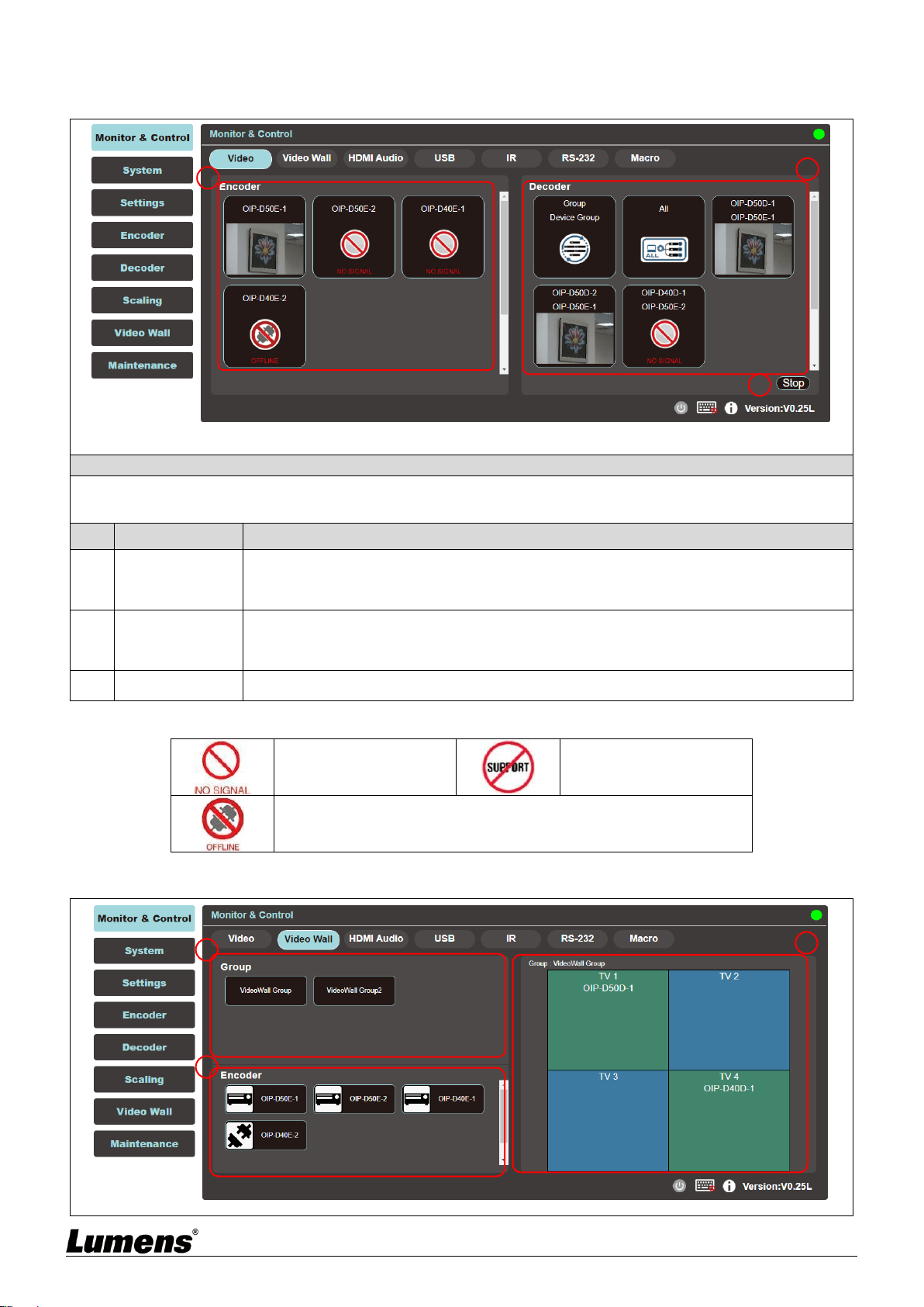
6.2 WebGUI Control Menu Descriptions
6.2.1 Monitor & Control - Image
Description
This tab is to preview the encoder, decoder, and video area in the connection, and you can use drag and drop to
change the signal settings.
No
Item
Function Descriptions
1
Preview of
Encoder Signal
Source
Drag and drop to assign signal sources to different decoders or groups.
2
Preview of
Decoder Video
Area
Display the preview thumbnail of the decoder signals, including the currently available
display groups.
3
Stop
Drag an object to this button and release to stop setting the object.
The thumbnail of the image source will be displayed under normal conditions, and the status icon will be
displayed under the following conditions:
When the encoder is
not currently connected
to the input source.
When the encoder or
decoder does not support
image thumbnails.
When the encoder or decoder is disconnected or not detected by
the main controller.
6.2.2 Monitor & Control – Video Wall
1
2
3
1
2
3
10
No
Item
Function Descriptions
1
Group
Show all current VideoWall groups
2
Encoder
Show all encoders, drag the encoder to the upper VideoWall group, and assign the source
to that VideoWall group.
3
Group View
Green for assigned sources, and blue for unassigned or not connected to the source.
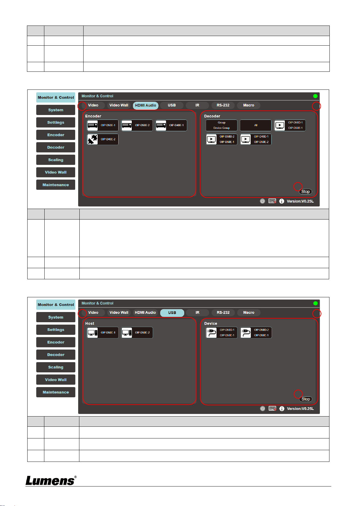
6.2.3 Monitor & Control - HDMI Audio
No
Item
Function Descriptions
1
Encoder
Show all current encoders. To assign HDMI audio sources to different decoders or groups,
drag and drop the encoder to the decoder or group to be set.
Click an encoder pane, and the corresponding decoder panes that receive the encoder
signals will all change their color.
2
Decoder
Displays all current decoder, and also the name of the source signal encoder.
3
Stop
Drag the object to the [Stop] button and release to stop setting the object.
6.2.4 Monitor & Control - USB
No
Item
Function Descriptions
1
Host
Display all current USB hosts (computers, laptops).
2
Device
It can be dragged to the USB host pane to complete the pairing.
3
Stop
Drag the object to the [Stop] button and release to stop setting the object.
1
2
3
1
2
3

11
6.2.5 Monitor & Control - IR
No
Item
Function Descriptions
1
Encoder
Show all current encoders with IR ports.
2
Decoder
Drag the encoder to the decoder pane to complete the device pairing.
3
Stop
Drag the object to the [Stop] button and release to stop setting the object.
6.2.6 Monitor & Control - RS-232
No
Item
Function Descriptions
1
Encoder
Show all current encoders with RS-232 port.
2
Decoder
The encoder can also be dragged to the decoder pane to complete the pairing.
3
Stop
Drag the object to the [Stop] button and release to stop setting the object.
1
2
3
1
2
3
12
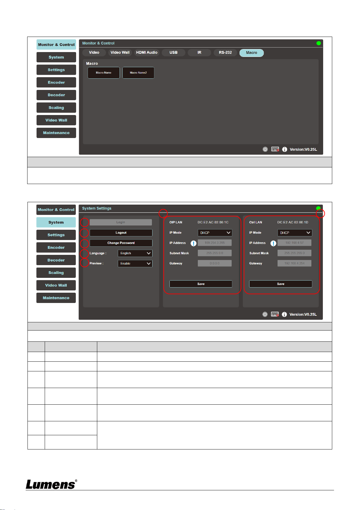
6.2.7 Monitor & Control - Macro
Description
Display the name of the currently set macro. Click to execute the set macro. Before the macro setting is
completed, the button will remain blue. Only one macro can be executed at the same time.
6.2.8 System
Description
This tab can access each system setting, including LAN settings and login and user management.
No
Item
Function Descriptions
1
Login
Default username and password are both [admin].
2
Logout
Click Logout button to log out WebGUI control page.
3
Change the
password
Click Change Password button to change the password of the WebGUI administrator.
4
Change the
Language
Open the drop-down menu to change the language to English/Chinese (Traditional)/
Chinese (Simplified).
5
Preview
Thumbnails
Open the drop-down menu to enable/disable preview thumbnails.
6
OIP LAN
Set OIP LAN and Ctrl LAN.
7
Ctrl LAN
1
2
3
4
5
6
7
13
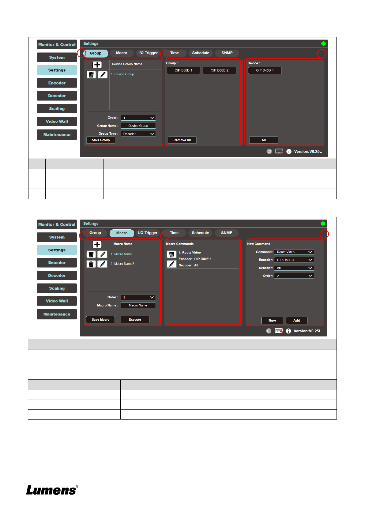
6.2.9 Settings - Group
No
Item
Function Descriptions
1
Device Group List
Show the currently set group list.
2
Group List
Show the decoders set by the selected group.
3
Device List
Show all available decoder devices.
6.2.10 Settings - Macro
Description
This tab provides a way to create operation commands, which can be controlled by an external IR remote control,
trigger, or from within the WebGUI. It can set a maximum of 16 macros, and each macro can contain up to 64
commands.
No
Item
Function Descriptions
1
Macro List
Show the currently set macro list.
2
Macro Commands Table
Show the commands list set in the currently selected macro.
3
New Command Setting
The new commands can be added here.
1
2
3
1
2
3
14
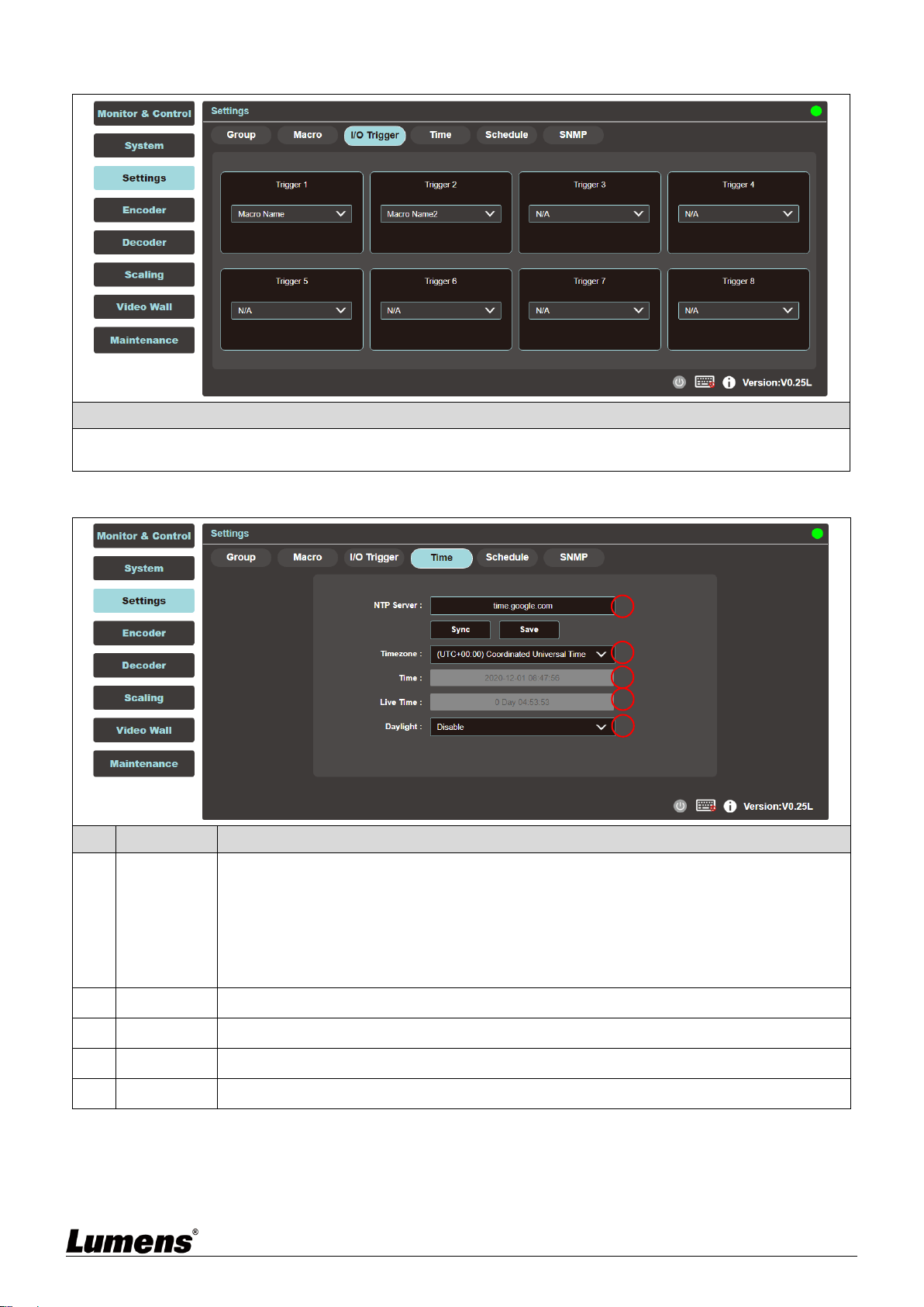
6.2.11 Settings - I/O Trigger
Description
This tab can set the macro to be triggered by the contactor. There are 8 buttons to be set. This setting also
applies to the IR remote control buttons.
6.2.12 Setting - Time
No
Item
Function Descriptions
1
NTP Server
Enter the host name or IP address of the preferred NTP server for time synchronization.
After changing the NTP server, click [Save] to save the settings. Click [Sync] to force the
device to synchronize to the NTP server immediately.
<Remark> The clock of this device has no backup battery, and the time setting will not be
preserved if the device is unplugged. But as long as both the Internet connection and the
NTP server are valid, the time setting will be automatically synchronized when the power is
on.
2
Time zone
Open the drop-down menu to select the time zone for your region.
3
Time
Show the current device time.
4
Live Time
Show how long the device has been online since the last restart.
5
Daylight
Select to enable/disable Daylight.
1
2
3
4
5
15
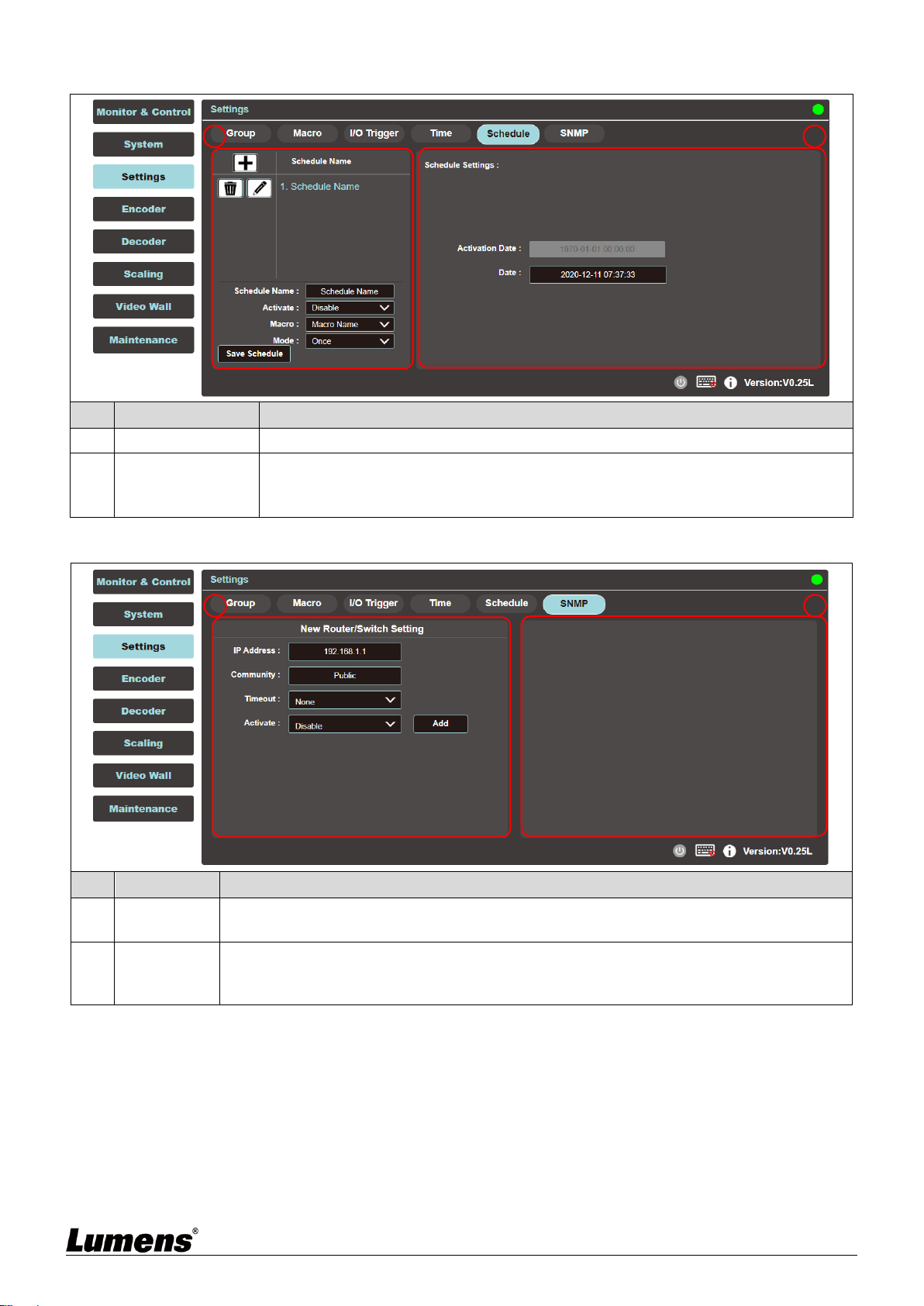
6.2.13 Settings - Schedule
No
Item
Function Descriptions
1
Schedule List
Show the currently set schedule list.
2
Schedule Settings
Show the schedule settings in different modes based on the set time mode.
(Once/repeat/cycle)
In repeat mode, enter “0” in the frequency field to repeat indefinitely.
6.2.14 Settings - SNMP
No
Item
Function Descriptions
1
Router/Switch
Settings
Enter the router or switch connection information to view its status and bandwidth usage.
2
Information
Window
Use SNMP to connect to a router or switch. The device shows green to indicate that the port
is connected, white to indicate that the port can be connected, and red to indicate an error.
Move the cursor to the port to display the related message.
1
2
1
2

16
6.2.15 Encoder
Description
This tab displays all the encoders that have been detected, and also shows the detailed data and related settings
of each encoder.
<Remark> If there is no available image source, the Image button will be red. Gray “N/A” means that the function
is not supported.
No
Item
Function Descriptions
1
Remove
It can remove unconnected encoder (marked ).
2
Hello
After clicking, the LED indicator on the front panel of the encoder flashes immediately,
making it easier to find the encoder. Click this button again to restore the normal
operation of the LED indicator.
3
Icon
Show the icon that represents the encoder. for connected; for unconnected.
4
Order
It can select the order of each encoder.
5
Name
Show the name of the encoder. Click Device > [Settings] to enter 12 letters or numbers
to change its name.
6
IP address
Show the IP address of the current encoder.
7
Video
Display the detailed information of the image input source.
<Remark> If there is no image source, the button is red.
8
Network
Click the [Settings] button to display detailed network information. The default mode is
Auto IP.
9
RS-232
Show the detailed information of the current RS-232 serial.
10
Device
Show the detailed information of the device. For detailed settings, please see 6.2.16
Encoder - Device Settings.
11
USB
Show the detailed information of the current USB, and the settings can be changed here.
The default is Auto Select mode. K/M Over IP and USB HID URB interval: A special
optimization function can be used to solve the abnormal response of the mouse or touch
screen. You can choose to enable or disable it. The default setting is disabled.
1
2
3
4
5
6
7
8
9
10
11
17
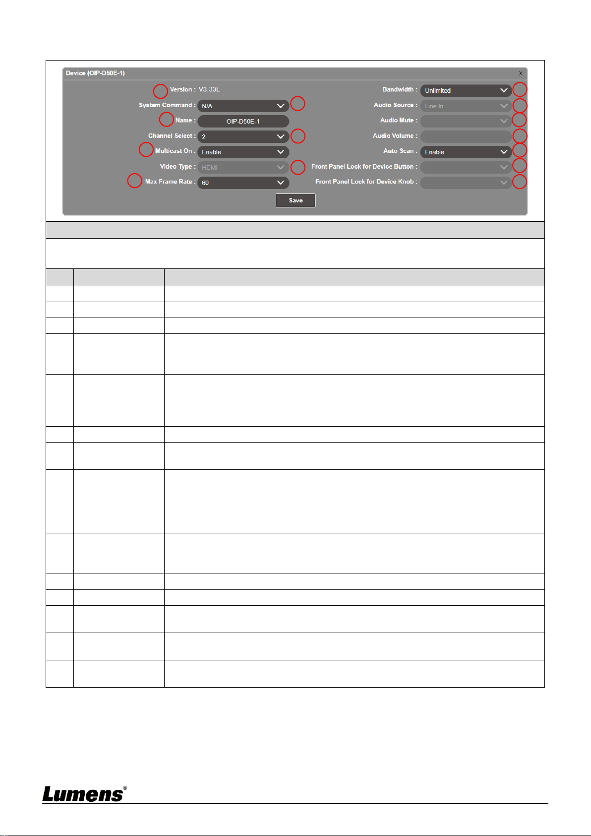
6.2.16 Encoder - Device Settings
Description
Show the message related to the setting of the encoder-end device. If the function drop-down menu is grayed out,
the function has automatically detected the source, or the connected encoder does not support this function.
No
Item
Function Descriptions
1
Version
Show the current firmware version of the device
2
System Command
Select System Command to reset or restart the device
3
Name
Change the device name (12 characters at most)
4
Channel Select
Select the broadcast channel of the encoder. Available range: 0 ~ 255.
<Remark> Each encoder in the same LAN needs to be allocated to different broadcast
channels to avoid conflicts.
5
Multicast On
Select to enable multicast mode when broadcasting, or use unicast mode when
disabled
<Remark> The decoder needs to use the same mode as the encoder to receive
image.
6
Video Type
Select the image input source on the device to be played.
7
Maximum Frame
Rate
Set the maximum frame rate, available range: 0 ~ 60.
8
Bandwidth
Set the maximum bandwidth for the image, available range: Unlimited/400M/200M/
100M/50M.
<Remark> When the input source is 4K image, although the recommended setting is
Unlimited, the bandwidth may be very big, which will limit the number of simultaneous
image streams.
9
Audio Source
Select the audio source, available options: HDMI/Line in/Auto
<Remark> This setting is stored independently for individual input sources, and the
default setting is Auto.
10
Audio Mute
This feature is currently not supported.
11
Audio Volume
This feature is currently not supported.
12
Auto Scan
The device will search the input signal (HDMI/VGA) automatically after this feature is
enabled.
13
Front Panel Lock
for Device Button
This feature is currently not supported.
14
Front Panel Lock
for Device Knob
This feature is currently not supported.
1
2
3
4
5
6
7
8
9
10
11
12
13
14
18
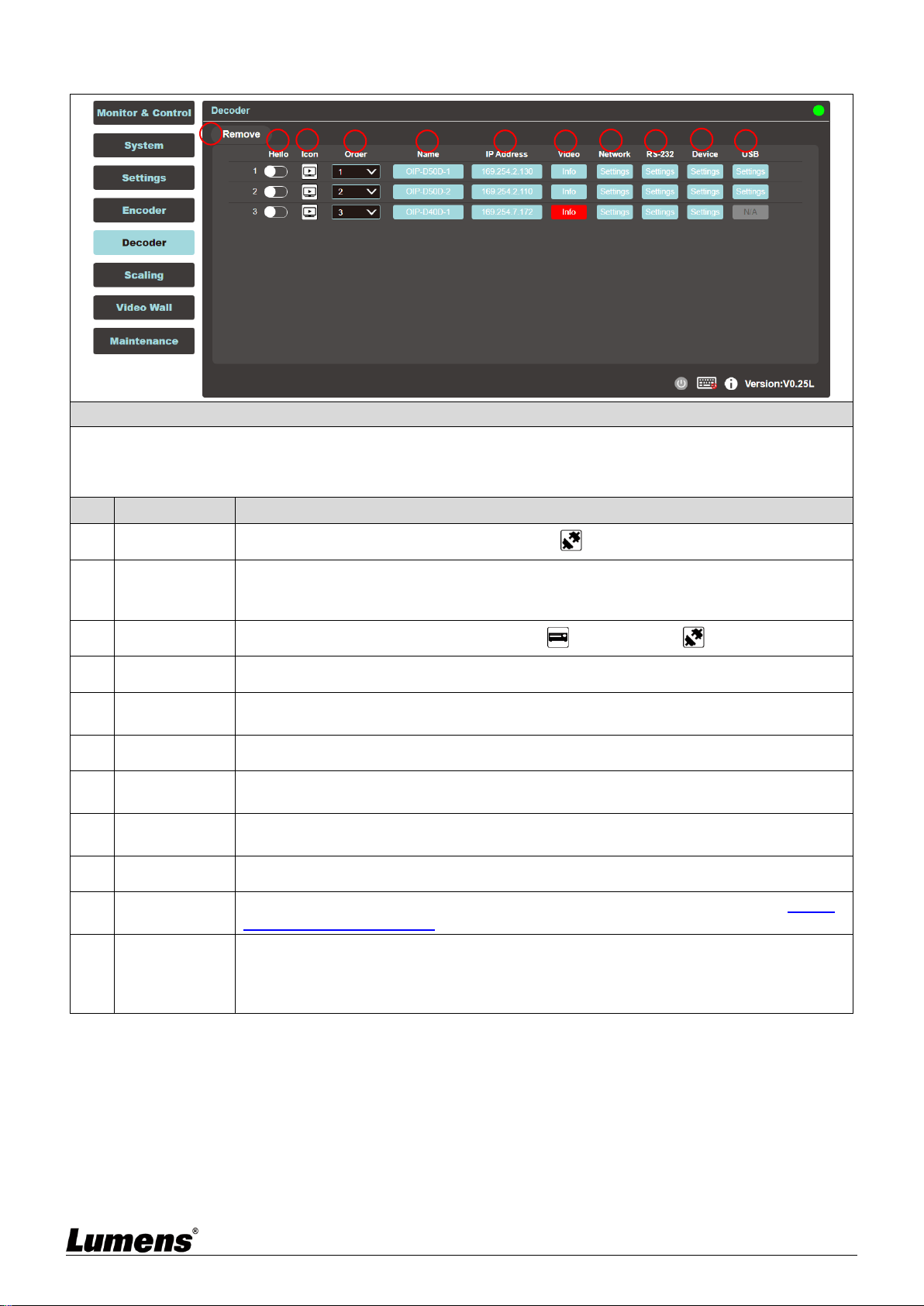
6.2.17 Decoder
Description
Show detailed data and related settings of all decoders.
<Remark> If there is no available image source, the Image button will be red, and gray “N/A” means that the
function is not supported.
No
Item
Function Descriptions
1
Remove
It can remove unconnected decoder (marked ).
2
Hello
After clicking, the LED indicator on the front panel of the decoder flashes immediately,
making it easier to find the decoder. Click this button again to restore the normal
operation of the LED indicator.
3
Icon
Show the icon that represents the decoder. for connected; for unconnected.
4
Order
It can select the order of each decoder.
5
Name
Show the name of the decoder. Click Device > [Settings] to enter 12 letters or numbers
to change its name.
6
IP address
Show the IP address of the current decoder.
7
Video
Display the detailed information of the image input source. <Remark> If there is no
image source, the button is red.
8
Network
Click the decoder [Settings] button to display detailed network information. The default
mode is Auto IP.
9
RS-232
Show the detailed information of the current RS-232 serial.
10
Device
Show the detailed information of the decoder. For detailed settings, please see 6.2.18
Decoder - Device Settings.
11
USB
Show the detailed information of the current USB, and the settings can be changed
here. The default is Auto Select mode. K/M Over IP and USB HID URB interval: A
special optimization function can be used to solve the abnormal response of the mouse
or touch screen. You can choose to enable or disable it. The default setting is disabled.
1
2
3
4
5
6
7
8
9
10
11
19
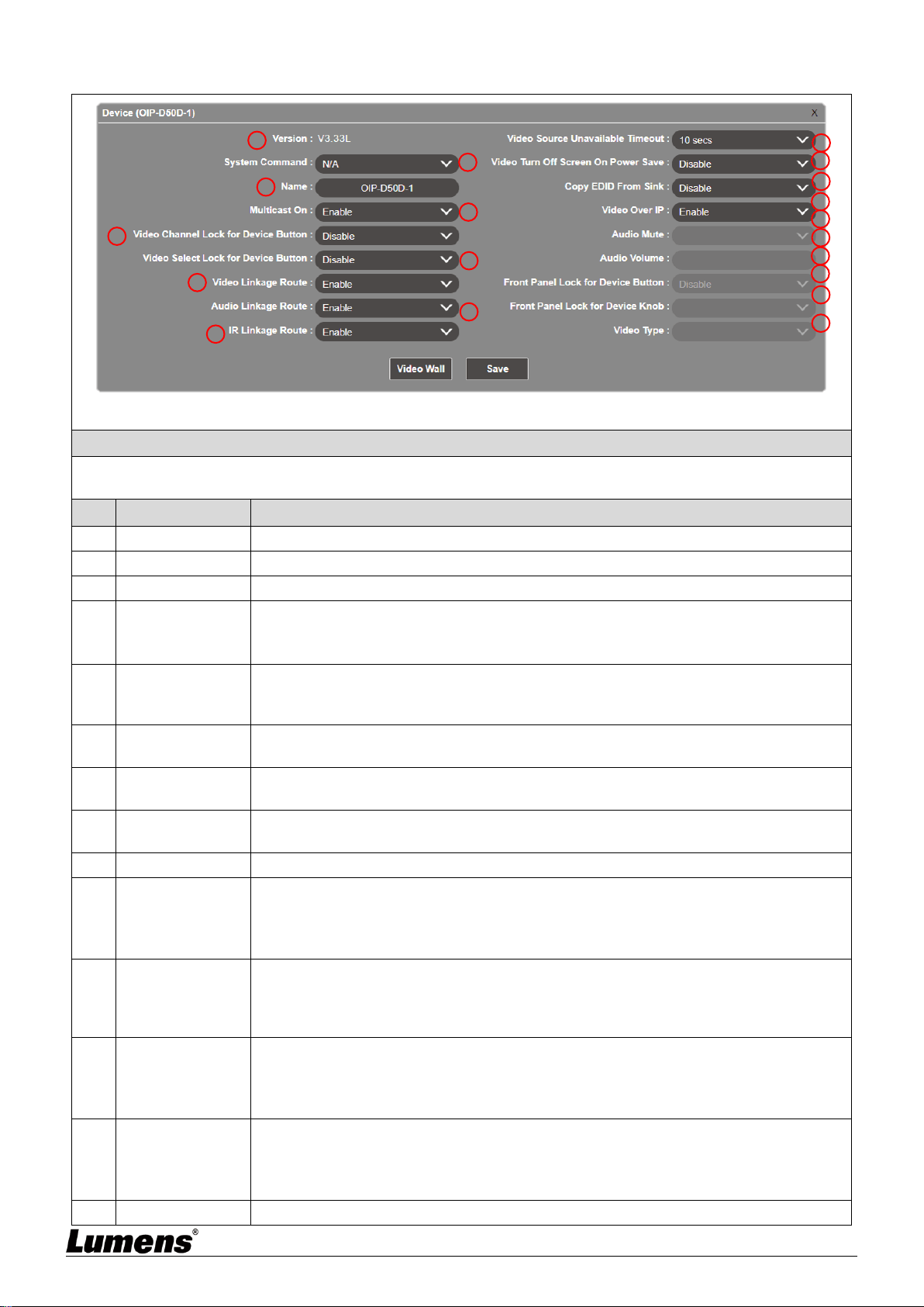
6.2.18 Decoder - Device Settings
Description
Show the message related to the setting of the decoder-end device. If the function drop-down menu is grayed out,
the function has automatically detected the source, or the connected decoder does not support this function.
No
Item
Function Descriptions
1
Version
Show the current firmware version of the device.
2
System Command
Select System Command to reset or restart the device.
3
Name
Change the device name (12 characters at most).
4
Multicast On
Select to enable or disable the multicast mode when broadcasting. When this function
is disabled, the unicast mode will be used for transmission.
<Remark> The decoder needs to use the same mode as the encoder to receive image.
5
Video Channel
Lock for Device
Button
When this setting is enabled, the image channel selection button will be locked and
cannot be used.
6
Video Select Lock
for Device Button
When this setting is enabled, the image input selection button will be locked and cannot
be used.
7
Video Linkage
Route
After selecting Enable, when the user switches the signal source, the image will switch
as well.
8
Audio Linkage
Route
After selecting Enable, when the user switches the signal source, the audio will switch
as well.
9
IR Linkage Route
After selecting Enable, when the user switches the signal source, IR will switch as well.
10
Video Source
Unavailable
Timeout
When the signal source is disconnected, the original screen will remain at the time set
by the user temporally, and then display OSD information (encoder/decoder IP, FW
version, connection status).
Available range: 3 sec/5 sec /10 sec /20 sec /30 sec /60 sec /Never
11
Video Turn Off
Screen On Power
Save
After the setting is enabled, when the signal source is disconnected, the original screen
will remain for the time set by the user temporally, and then the display will enter the
Power save mode. After the setting is disabled, the screen will keep showing “Lost
Connection” until the connection is restored.
12
Copy EDID From
Sink
When multiple decoders are connected to a single encoder in multicast mode, enabling
this on one receiver selects which of the decoders should send its EDID to the encoder
for use with the source.
<Remark> This option is only valid in multicast mode.
13
Video Over IP
The default value is enabled. If it is disabled, image and audio cannot be transmitted
through AV over IP technology.
<Remark> This option should always remain enabled status, unless troubleshooting is
being performed.
14
Audio Mute
This feature is currently not supported.
5
1
2
3
4
6
7
8
9
10
11
12
13
14
15
16
17
18
19
20
15
Audio Volume
This feature is currently not supported.
16
Front Panel Lock
for Device Button
This feature is currently not supported.
17
Front Panel Lock
for Device Knob
This feature is currently not supported.
18
Video Type
Select the image input source on the device to be played.
19
Video Wall
Click this button to create a new window to configure the settings of the current Video
Wall of this decoder. For detailed setting content, please see 6.2.20 Video Wall.
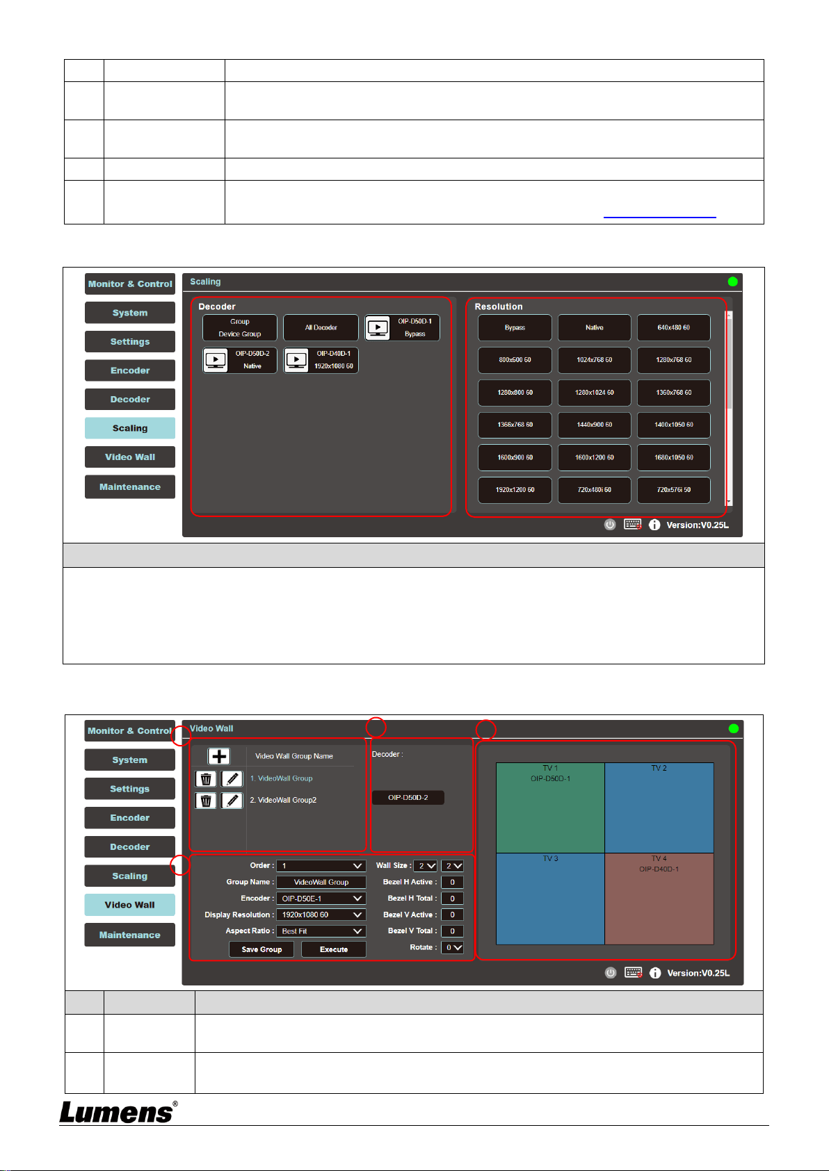
6.2.19 Scaling
Description
This tab can set the image output resolution of each decoder.
Click the decoder to be set on the left, then drag it to the resolution to be set on the right and release it. After the
setting is completed, the set resolution will be displayed under the decoder name. You can also directly drag and
drop the resolution to the decoder button to change the output resolution.
Bypass: The decoder will output all signals at its original resolution.
Native: The decoder will use the resolution provided by the EDID of the connected display to output signals.
6.2.20 Video Wall
No
Item
Function Descriptions
1
VideoWall
Group List
Show the currently set VideoWall group list.
2
Settings
Order: It can sort different VideoWall groups.
Group Name: Set the name of a VideoWall group.
1
2
3
4
21
Encoder: Set the image source.
Display Resolution: You can select the Display Resolution of all decoders in this VideoWall
group.
Aspect Ratio: It can be set to [Full Screen] or [Best Fit].
Wall Size: Set the size of the Video Wall, and the maximum number of displays is 256
(16*16).
Bezel H/V Total & H/V Active: Set the actual size of all displays in the Video Wall.
<Remark> It is recommended that the displays in the Video Wall use the same brand and
model to avoid the difference in the size of the frame and the panel.
Rotate: Set the rotation angle of the image (0°/180°/270°)
3
Decoder
Show all currently available decoders. Place all decoders onto the Video Wall on the right.
4
VideoWall
Preview
Display the preview image of the decoder currently assigned by the Video Wall. If the
display on the Video Wall has been assigned, it will show the name of the assigned
receiver.
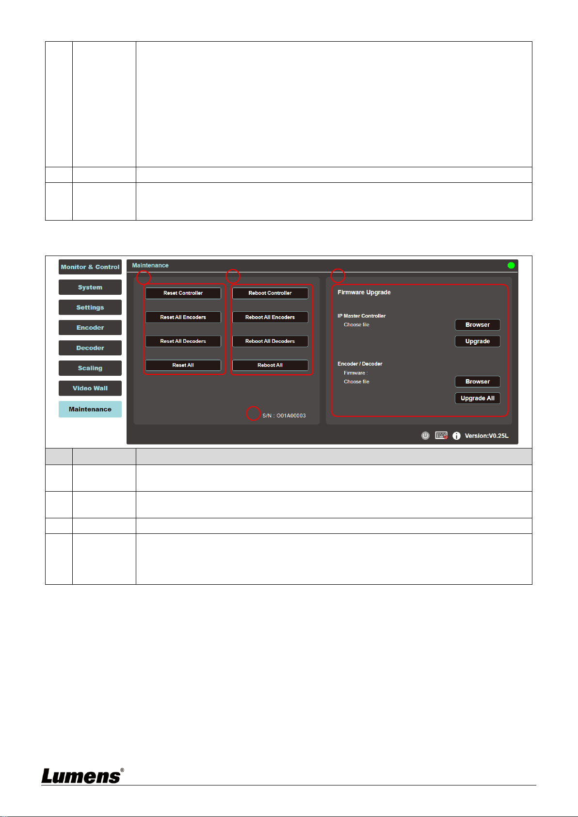
6.2.21 Maintenance
No
Item
Function Descriptions
1
Reset
Controller
Reset will restore the device to its initial settings. Click on the option to reset all connected
controllers, encoders, decoders, or all devices.
2
Reboot
Controller
Reboot will restart the device, and all settings will be retained. Click the option to reboot all
connected controllers, encoders, decoders, or all devices.
3
Serial No.
It shows the serial number of this connected controller.
3
Firmware
Upgrade
You can update the firmware version of the controller, encoder, and decoder.
Click [Choose File] and select the correct updated file (bin format) from the computer. After
choosing the file, click [Upgrade] to start updating the program. Once the update is
finished, the device will restart.
1
2
3
4

22
Chapter 7 Troubleshooting
This chapter describes problems you may encounter while using OIP-D50C. If you have
questions, please refer to related chapters and follow all the suggested solutions. If the problem
still occurred, please contact your distributor or the service center.
No.
Problems
Solutions
1.
The signal source screen is
not shown on the display-end.
1. Please check whether the Multicast of the encoder and decoder
is enabled: Enter the WebGUI control interface of the D50C
controller, then click Device - [Settings] on the Encoder-end and
Decoder-end tabs to check whether Multicast is enabled.
2. Make sure the source is set to HDMI or VGA: (Only applicable to
D50E/D50D)
(1) Enter the WebGUI control interface of the D50C controller, and
click Device - [Settings] on the Encoder-end tab to check that the
Video type is set to HDMI or VGA.
(2) On the front panel of the decoder host, press the Mode button
to switch between HDMI and VGA signal sources.
<Remark> You must choose the same signal source for the
encoder and decoder as HDMI or VGA. If they are not consistent,
the signal source screen will not be displayed.
2.
Image delay on the
display-end
1. Check whether the MTU of the encoder and decoder is enabled
(default is enabled):
Enter “GET_JUMBO_MTU” in the Command field in the WebGUI
interface system - Utility Program tab, and the Output below will
show whether the status of jumbo frame MTU is enabled or
disabled. If it is disabled, please enter “SET_JUMBO_MTU 1” in
the Command field to enable it, and follow the instructions to
restart the device to implement the changes.
2. The streaming mode may be Graphic Mode: (Only applicable to
D50E/D50D)
On the front panel of the decoder host, press the Mode button to
switch between the Video/Graphic modes. Please switch to the
Video mode.
3.
The image on the display-end
is broken or black
Check that the Jumbo Frame of the switch is set to above 8000;
Please make sure that IGMP Snooping of the switch and relevant
settings (Port, VLAN, Fast Leave, Querier) has been set to
“Enable”.
<Remark> At least 5V DC current is required to activate the contactor.
23
Chapter 8 Safety Instructions
Always follow these safety instructions when setting up and using this product:
1 Operation
1.1 Please use the product in the recommended operating environment, away from water or source of heat
1.2 Do not place the product on a tilted or unstable trolley, stand or table.
1.3 Do not open or remove covers, otherwise it may expose you to dangerous voltages and other hazards.
Refer all servicing to licensed service personnel.
2 Storage
2.1 Do not place the product where the cord can be stepped on as this may result in fraying or damage to the
lead or the plug.
2.2 Unplug this product during thunderstorms or if it is not going to be used for an extended period.
2.3 Do not place this product or accessories on top of vibrating equipment or heated objects.
3 Cleaning
3.1 Disconnect all the cables prior to cleaning and wipe the surface with a dry cloth. Do not use alcohol or
volatile solvents for cleaning.
Precautions
This symbol indicates that this equipment may
contain dangerous voltage which could cause
electric shock. Do not remove the cover (or
back). No user-serviceable parts inside. Refer
servicing to licensed service personnel.
This symbol indicates that there are
important operating and
maintenance instructions in this
User Manual with this unit.
FCC Warning
This equipment has been tested and found to comply with the limits for a Class B digital device, pursuant to part
15 of the FCC Rules. These limits are designed to provide reasonable protection against harmful interference in
a residential installation. This equipment generates, uses and can radiate radio frequency energy and, if not
installed and used in accordance with the instructions, may cause harmful interference to radio communications.
However, there is no guarantee that interference will not occur in a particular installation. If this equipment does
cause harmful interference to radio or television reception, which can be determined by turning the equipment off
and on, the user is encouraged to try to correct the interference by one or more of the following measures:
- Reorient or relocate the receiving antenna.
- Increase the separation between the equipment and receiver.
- Connect the equipment into an outlet on a circuit different from that to which the receiver is connected.
- Consult the dealer or an experienced radio/TV technician for help.
Notice :
The changes or modifications not expressly approved by the party responsible for compliance could void the
user’s authority to operate the equipment.
This equipment has been tested and found to comply with the limits for a Class B digital device, pursuant to part
15 of the FCC Rules. These limits are to provide reasonable protection from harmful interference in residential
installations.
IC Warning
This digital apparatus does not exceed the Class B limits for radio noise emissions from digital apparatus as set
out in the interference-causing equipment standard entitled “Digital Apparatus,” ICES-003 of Industry Canada.
Cet appareil numerique respecte les limites de bruits radioelectriques applicables aux appareils numeriques de
Classe B prescrites dans la norme sur le material brouilleur: “Appareils Numeriques,” NMB-003 edictee par
l’Industrie.
EN55032 CE Warning
Operation of this equipment in a residential environment could cause radio interference.
Warning: Operation of this equipment in a residential environment may cause radio interference.

24
Copyright Information
Copyrights © Lumens Digital Optics Inc. All rights reserved.
Lumens is a trademark that is currently being registered by Lumens Digital Optics Inc.
Copying, reproducing or transmitting this file is not allowed if a license is not provided by Lumens Digital Optics
Inc. unless copying this file is for the purpose of backup after purchasing this product.
In order to keep improving the product, the information in this file is subject to change without prior notice.
To fully explain or describe how this product should be used, this manual may refer to names of other products or
companies without any intention of infringement.
Disclaimer of warranties: Lumens Digital Optics Inc. is neither responsible for any possible technological,
editorial errors or omissions, nor responsible for any incidental or related damages arising from providing this file,
using, or operating this product.
