
To download the latest version of Quick Start
Guide, multilingual user manual, software, or
driver, etc., please visit Lumens
https://www.MyLumens.com/support
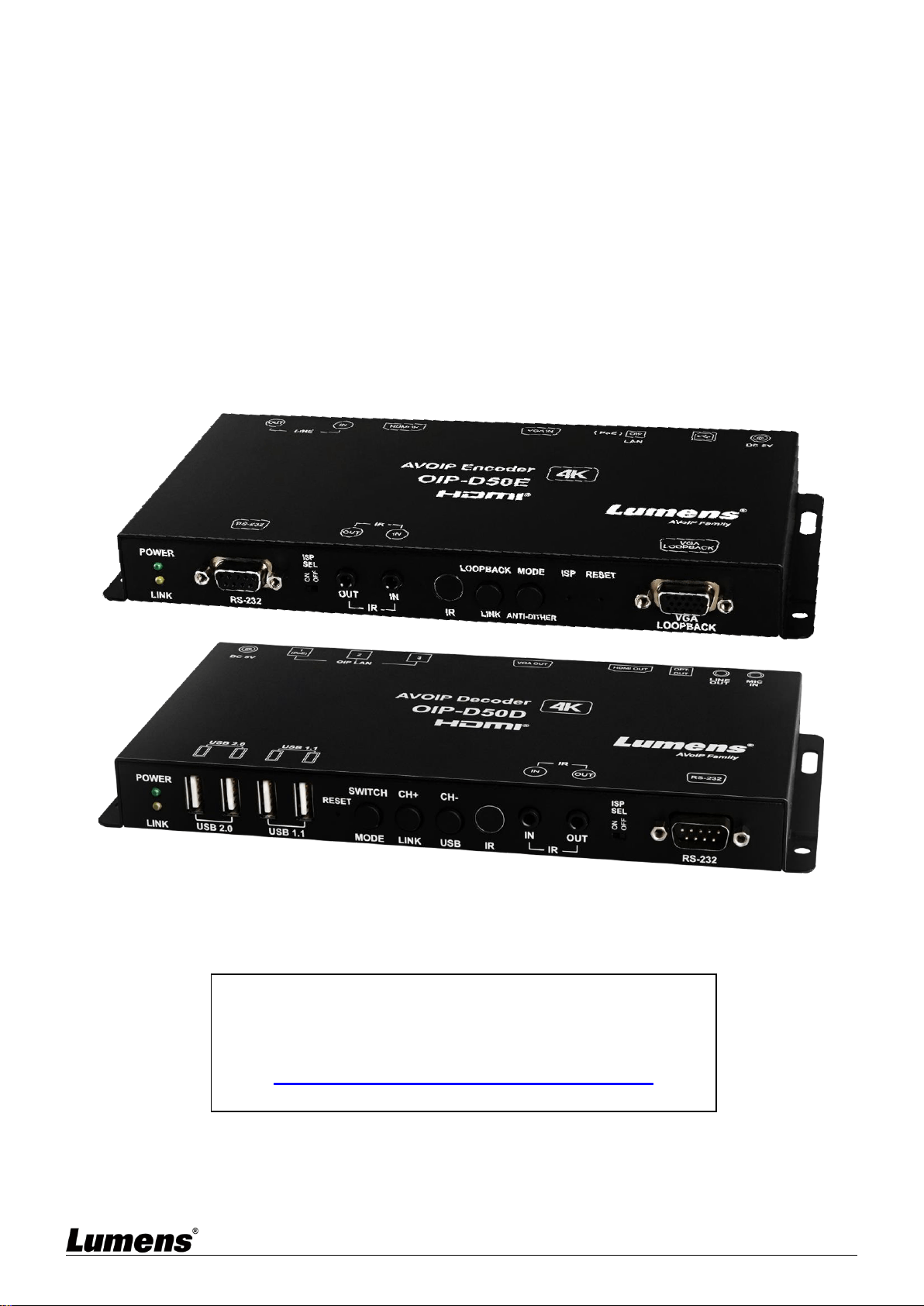
OIP-D50E/D50D
AVoIP Encoder / AVoIP Decoder
User Manual - English
[Important]

1
Table of Contents
Chapter 1 Package Contents ...................................................................... 2
1.1 OIP-D50E Encoder ........................................................................................... 2
1.2 OIP-D50D Decoder ........................................................................................... 2
Chapter 2 Product Overview ...................................................................... 3
2.1 Overview ........................................................................................................... 3
2.2 Product Applications ......................................................................................... 3
2.3 System Requirements ....................................................................................... 3
2.4 I/O Functions Introduction ................................................................................. 4
2.5 Description of Indicator Display ......................................................................... 8
2.6 IR Pin Assignment Configuration ...................................................................... 8
2.7 RS-232 Communication Protocol ...................................................................... 8
Chapter 3 Installation and Connections .................................................... 9
3.1 Connection diagram .......................................................................................... 9
3.2 Connection Setting .......................................................................................... 10
Chapter 4 Start Using ................................................................................ 11
4.1 Network Switch Setting ................................................................................... 11
4.2 WebGUI Control Methods ............................................................................... 11
Chapter 5 WebGUI Control Menu ............................................................. 12
5.1 WebGUI Control Menu Descriptions ............................................................... 12
Chapter 6 KVM Function ........................................................................... 21
6.1 KVM Descriptions ............................................................................................ 21
6.2 KVM Operation ................................................................................................ 21
Chapter 7 Product Specification .............................................................. 23
7.1 Technical Specification ................................................................................... 23
7.2 Image Specification ......................................................................................... 24
7.3 Audio Specification .......................................................................................... 25
Chapter 8 Troubleshooting ....................................................................... 26
Chapter 9 Safety Instructions ................................................................... 27
Copyright Information ............................................................................... 28

2
Chapter 1 Package Contents
1.1 OIP-D50E Encoder
OIP-D50E Encoder
Instruction for
installation
5 V/2.6 A Power supply
(including a
multinational adapter)
3.5mm to infrared
emitter
3.5mm to infrared
extender
Foot mats
(A set of four)
1.2 OIP-D50D Decoder
OIP-D50D
Decoder
Instruction for
installation
5V/4A Power
supply
Power Cord
3.5mm to infrared
emitter
3.5mm to infrared
extender
Foot mats
(A set of four)

3
Chapter 2 Product Overview
2.1 Overview
This product is a multifunctional VoIP encoder/decoder. It can extend HDMI or VGA signals and
connect KVM remote control through Cat.5e/6/7 cable under TCP/IP protocol. This product supports
ultra HD images (4K@30 Hz YUV 4:4:4 or 4K@60 Hz YUV 4:2:0), digital or analog sound and USB
data, and the transmission distance can reach 100 meters. If it is equipped with a Gigabit network
switch, it can not only extend the transmission distance (up to 100 meters for each connection), but
also receive VoIP signals without loss or delay.
This product supports Multicast of VoIP signals, which can send audio-visual signals of one encoder
to multiple decoders in the same local network. In addition, VoIP signals with multicast can also be
used to build a large video wall composed of multiple displays, which is perfectly suitable for home
use and commercial audio-visual installation environments.
In addition to supporting IR and RS-232 bidirectional transmission, this product also has analog
line-level sound input or output and microphone audio input (in the decoder), providing more sound
effect options. In addition, it supports USB function to combine with VGA signals, allowing you to
use this product as a remote USB hub and provide easy KVM switch. This product has a screen
display function to quickly check setting information. The control interface includes WebGI, Telnet
and front panel buttons.
2.2 Product Applications
HDMI or VGA audio/video, USB, audio, IR and RS-232 signal extension
Use one Cat.5e/6/7 network cable to broadcast the audio-visual system
Play multimedia on multiple displays with multicasting
Multi-screen broadcast displays in restaurants or conference centers
Use connection to long-distance transmit data and images
Matrix image distribution system
Video wall image distribution system
Keyboard, displays and mouse remote control
2.3 System Requirements
HDMI or VGA audio-visual source devices, such as digital media players, video game consoles, PCs or
set-top boxes.
An HDMI or VGA audio-visual equipment, such as a HD TV, screen or audio-visual amplifier.
Analog audio equipments, such as headphones, audio-visual amplifiers, or power-supplied speakers.
A Gigabit network switch supports Jumbo Frame (at least 8K Jumbo Frames).
A Gigabit network switch supports Internet Group Management Protocol (IGMP) Snooping.
4
2.4 I/O Functions Introduction
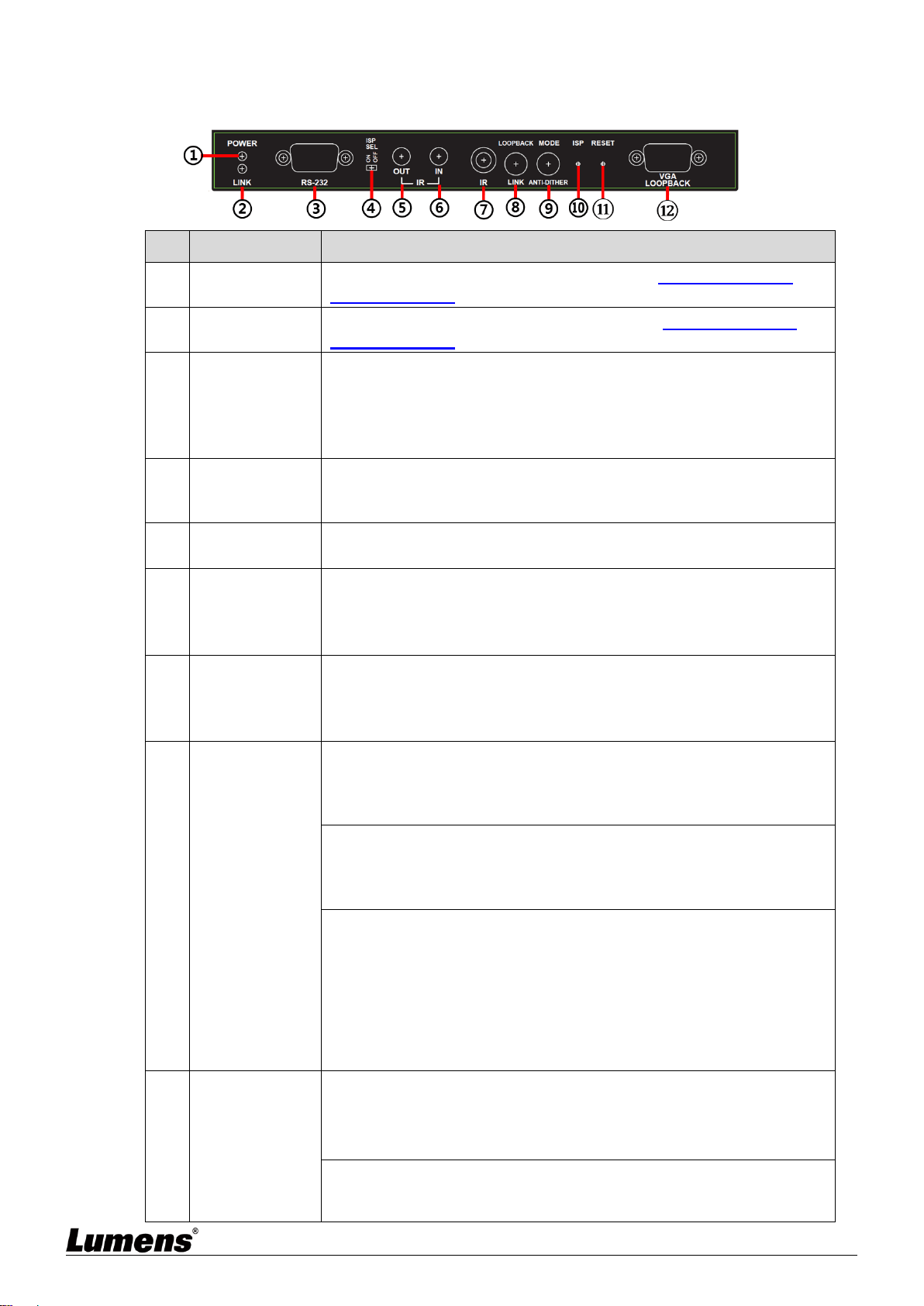
2.4.1 OIP-D50E Encoder - Front Panel
NO
Item
Function Descriptions
①
Power Indicator
Display the status of the device. Please refer to 2.5 Description of
Indicator Display.
②
Connection
Indicator
Display the status of connection. Please refer to 2.5 Description of
Indicator Display.
③
RS-232 Port
Connect to a computer to issue RS-232 commands to RS-232 controlled
devices. The default baud rate is 115200 bps, which can be set by users.
<Remark> With Multicast, the encoder can send RS-232 commands to
all decoders, and individual decoders can send RS-232 commands to
the encoder.
④
ISP SEL On/Off
For manufacturers only. The default position of this switch is OFF, which
can perform normal RS-232 transmission function. If the switch is on, the
ISP engineering mode will be activated.
⑤
IR Output Port
After connecting to IR emitter, aim at the controlled device to send the
received IR signals from the remote control to the controlled device.
⑥
IR Input Port
After connecting to IR extender, aim at the remote control to extend the
IR control range of the remote control to the far ends.
<Remark> With Multicast, the encoder can send IR signals to all
decoders.
⑦
IR Receive
Window
It can receive IR signals from any standard remote control and send the
received IR signals to the IR output port on the decoder.
<Remark> With Multicast, the encoder can send IR signals to all
decoders.
⑧
Loopback or
Link Button
(1) Image Loopback: Press this button to enable or disable the VGA
loopback output, which can be used to locally monitor the current VGA or
HDMI signal source (non-HDCP encryption and resolution is 1080p or
below) for troubleshooting.
(2) Image Connection: Press this button for 3 seconds to enable or
disable image connection. When the video connection is disabled, the
display connected to the receiver will show the current IP address and
firmware version of the system.
(3) Resume the factory default setting: In the unplugged state, press and
hold this button, and then insert the power. When the POWER and LINK
indicators flash at the same time, it means the factory settings have been
restored (it takes 15~30 seconds). Then, release the button, and restart
the device.(including restoring the IP mode to Auto, the broadcast
channel to 0, and the cast mode to Multicast). The IP address of this
device will also automatically assign. The new address range is
169.254.XXX.XXX.
⑨
Image Stream
and Anti-dither
Button
(1) Image Stream: Press this button to select the image stream, you can
switch between Graphic and Video image processing modes.
Graphic mode: Optimizing high-resolution static images.
Video mode: Optimizing full motion images.
(2) Anti-dither: Press this button for 3 seconds to enable anti-dither. You
can switch between 1-bit, 2-bit, or Off processing modes. Some display
adapters adopt dithering technology to simulate more colors, but
5
NO
Item
Function Descriptions
dithering processing make low-broadband signals difficult to save, when
processing live image compression. This function will remove the
dithering processing and then compress and transmit signals. If the
signal source has not been dithered, do not enable this function.
<Remark> Anti-dither is off by default (Off mode).
⑩
ISP Button
For manufacturers only.
⑪
Reset Button
Press this button to restart the device (all settings will be retained).
⑫
VGA Loopback
Output Port
Connect to a VGA display to output analog images, which can be used to
locally monitor the current VGA or HDMI signal sources (non-HDCP
encryption, and the resolution is 1080p or below).
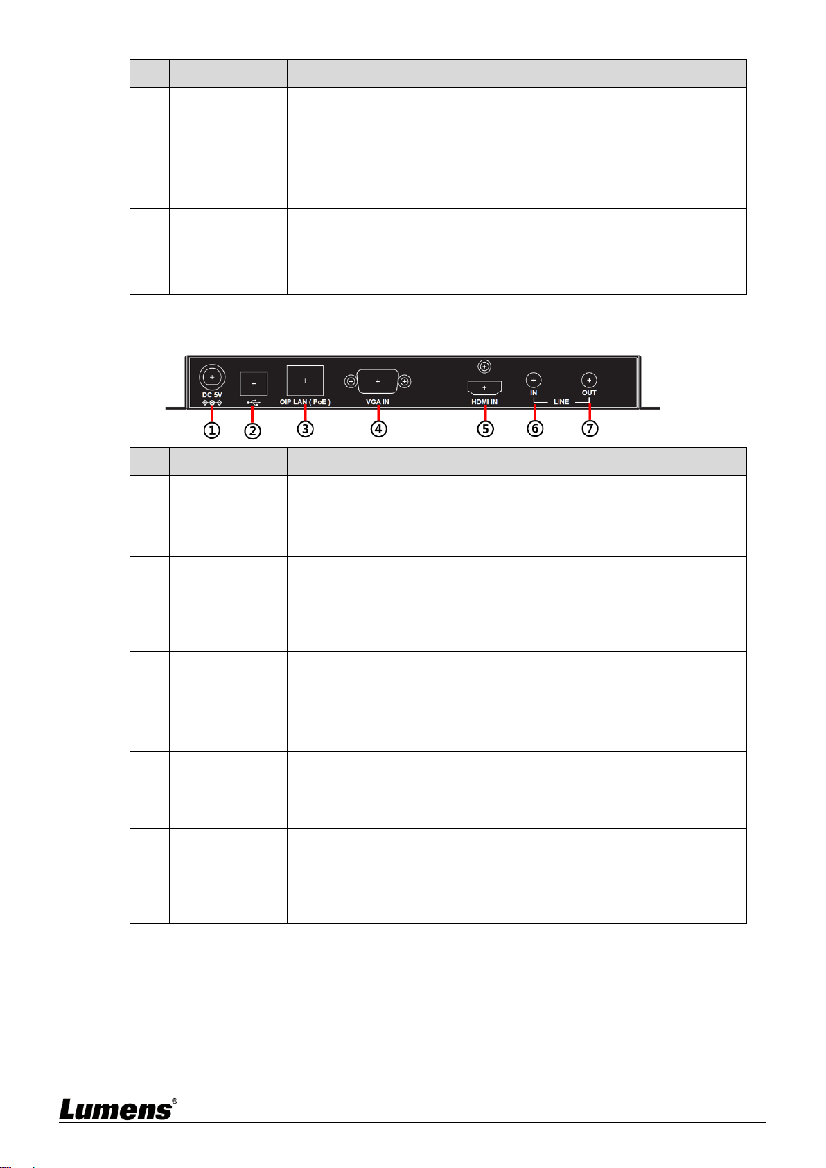
2.4.2 OIP-D50E Encoder - Rear Panel
NO
Item
Function Descriptions
①
Power Port
Plug in the 5V DC power supply and connect to an AC outlet (or choose
to supply power via PoE).
②
USB Port
Connect to a computer and expand its USB function to the USB port of a
compatible decoder.
③
OIP LAN Port
Connect to a network switch to serially connect a compatible decoder to
transmit data, or connect to a computer to use WebGUI to operate the
device.
<Remark> If the network switch adopts PoE (IEEE 802.3af) technology,
power can be obtained directly from the network switch.
④
VGA input port
Connect to a VGA source device, such as a desktop computer or laptop.
<Remark> When sending 4K@60 Hz (YUV 4:2:0) images from a
computer, image signals may have artifacts.
⑤
HDMI Input Port
Connect to HDMI source devices, such as digital media players, video
game consoles or set-top boxes, and HD cameras.
⑥
LINE Input Port
Connect to a CD player or computer to input analog audio.
<Remark> When this input port has a signal source, this device will
embed the audio into signals to be transmitted, and the original HDMI
audio will be replaced completely.
⑦
LINE Output
Port
Connect to a power-supplied speaker or AV amplifier to output analog
audio, which can only play the microphone signal sources from the
decoder (limited to unicast mode).
<Remark> The LINE input port on the encoder must be connected to a
signal source to enable the microphone on the decoder.
6
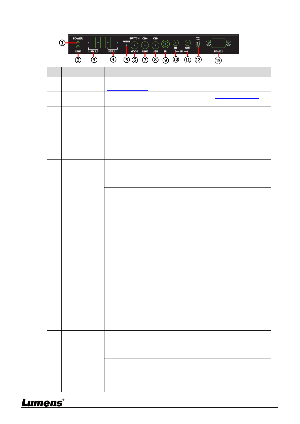
2.4.3 OIP-D50D Decoder - Front Panel
NO
Item
Function Descriptions
①
Power Indicator
Display the status of the device. Please refer to 2.5 Description of
Indicator Display.
②
Connection
Indicator
Display the status of connection. Please refer to 2.5 Description of
Indicator Display.
③
USB 2.0 port
Connect to High Speed USB peripherals, such as USB disk.
<Remark> This does not support isochronous transmission of USB
access devices, such as digital cameras and external hard drives.
④
USB 1.1 port
Connect to Full Speed USB peripherals, such as a keyboard or a mouse.
<Remark> This does not support isochronous transmission of USB
access devices, such as digital cameras and external hard drives.
⑤
Reset Button
Press this button to restart the device (all settings will be retained).
⑥
Signal Source
and Image
Stream button
(1) Signal source: Press this button to select the signal source. You can
switch between HDMI and VGA image signals.
<Remark> Due to the requirements of streaming image and HDCP
encryption, the switching time will be at least 6 - 10 seconds.
(2) Image Stream: Press this button for 3 seconds to select the image
stream. You can switch between Graphic and Video image processing
modes.
Graphic mode: Optimizing high-resolution static images
Video mode: Optimizing full motion images
⑦
Channel or Link
button
(1) Channel +: Press this button to switch to the next available streaming
channel in the local network.
<Remark> If the device does not detect an available streaming channel,
its channel number will not be changed.
(2) Image Connection: Press this button for 3 seconds to enable or
disable image connection. When the video connection is disabled, the
display connected to the receiver will show the current IP address and
firmware version of the system.
(3) Resume the factory default setting: In the unplugged state, press and
hold this button, and then insert the power. When the POWER and LINK
indicators flash at the same time, it means the factory settings have been
restored (it takes 15~30 seconds). Then, release the button, and restart
the device.(including restoring the IP mode to Auto, the broadcast
channel to 0, and the cast mode to Multicast). The IP address of this
device will also automatically assign. The new address range is
169.254.XXX.XXX.
⑧
Channel or USB
Button
(1) Channel -: Press this button to switch to the previous available
streaming channel in the local network.
<Remark> If the device does not detect an available streaming channel,
its channel number will not be changed.
(2) USB Connection: Press this button for 3 seconds to enable or disable
the USB connection between the encoder and decoder (limited to
multicast).
<Remark> With multicast, only one decoder can enable the USB
connection with the encoder at a time, and other decoders on the same

7
NO
Item
Function Descriptions
channel will not be able to enable their USB connection.
⑨
IR Receive
Window
It can receive IR signals from any standard remote control and send the
received IR signals to the IR output port on the encoder.
⑩
IR Input Port
After connecting to IR extender, aim at the remote control to extend the
IR control range of the remote control to the far ends.
⑪
IR Output Port
After connecting to IR emitter, aim at the controlled device to send the
received IR signals from the remote control to the controlled device.
⑫
ISP SEL On/Off
For manufacturers only. The default position of this switch is OFF, which
can perform normal RS-232 transmission function. If the switch is on, the
ISP engineering mode will be activated.
⑬
RS-232 Port
Connect to the RS-232 controlled device to execute RS-232 commands
of the computer. The default baud rate is 115200 bps, which can be set
by users.
<Remark> With Multicast, the encoder can send RS-232 commands to
all decoders, and individual decoders can send RS-232 commands to
the encoder.
2.4.4 OIP-D50D Decoder - Rear Panel
NO
Item
Function Descriptions
①
Microphone
Input Port
Connect to a microphone to input analog audio, which is played by the
LINE output port on the encoder (limited to unicast mode).
<Remark> The LINE input port on the encoder must be connected to a
signal source to enable the microphone on the decoder.
②
LINE Output
Port
Connect to a power-supplied speaker or AV amplifier to output analog
audio, which can play HDMI or Line-level signal source from the
encoder, and support LPCM 2.0 sound effect.
③
Optical output
port
Connect to a power-supplied speaker or AV amplifier to output digital
audio, which can play HDMI or Line-level signal source from the
encoder, and support LPCM 2.0 & Bitstream sound effect.
④
HDMI output
port
Connect to HDMI display or audio-visual amplifier to output digital
images and audio.
⑤
VGA output port
Connect to a VGA display to output analog images (limited to VGA or
non-HDCP encrypted HDMI signal source).
<Remark> When sending 4K@60 Hz (YUV 4:2:0) images from a
computer, image signals may have artifacts.
⑥
ISP Button
For manufacturers only.
⑦
OIP LAN Port
Connect to a network switch to serially connect a compatible encoder to
transmit data, or connect to a computer to use WebGUI to operate the
device.
<Remark> If the network switch adopts PoE (IEEE 802.3af) technology,
power can be obtained directly from the network switch. For PoE power
supply, please connect to OIP1. For serial connection, please use any
port.
⑧
Power Port
Plug in the 5V DC power supply and connect to an AC outlet (or choose
to supply power via PoE).
8
2.5 Description of Indicator Display
Name
Indicator Status
Power Indicator
Flickering: Receiving power
Stays On: Ready
Connection Indicator
Off: No internet connection
Flickering: Connecting
Stays On: Connection is stable
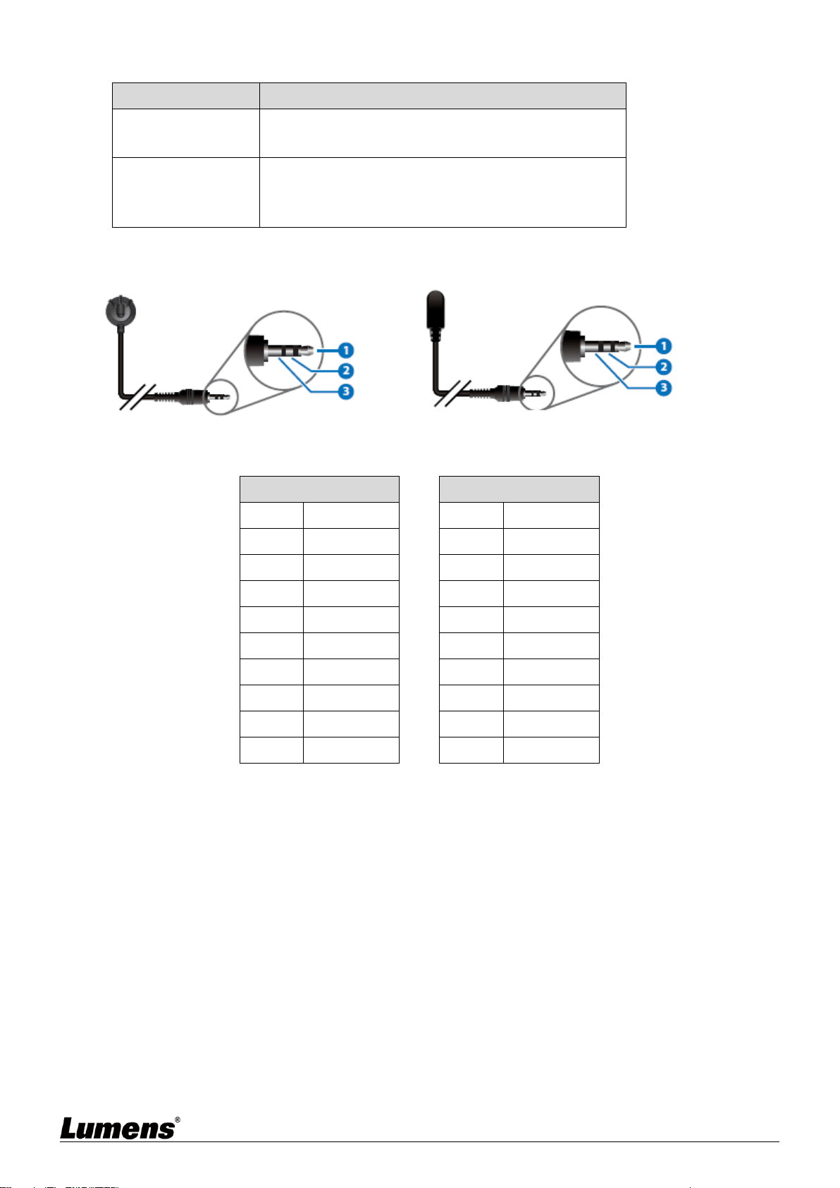
2.6 IR Pin Assignment Configuration
2.7 RS-232 Communication Protocol
Encoder
►
◄
Decoder
Pin
Configuration
Pin
Configuration
1
NC
1
NC
2
Tx
2
Rx
3
Rx
3
Tx
4
NC
4
NC
5
GND
5
GND
6
NC
6
NC
7
NC
7
NC
8
NC
8
NC
9
NC
9
NC
IR extender
IR
Power
Grounding
Power
IR
Without connection
IR emitter
9
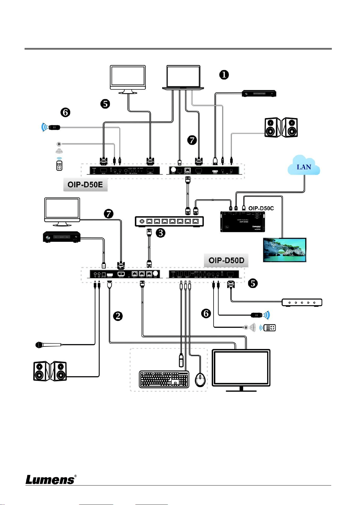
Chapter 3 Installation and Connections
3.1 Connection diagram
Video display device
Media player
RS-232
connection
Network switch
(supported for PoE)
HDMI
Input
Analog stereo
output
Microphone Input
IR Input
Video/Audio
Amplifier
IR Input
IR Output
IR Output
RS-232
connection
OIP-D50C
HDMI
Output
Monitor
Monitor
Computer
VGA
loopback output
VGA
Input
Speaker
Analog stereo
input
USB
connection
VGA
Output
Digital stereo
Output
Controlled device
Smart TV
USB peripheral
devices
Digital Stereo
Output
Speaker
LAN
connection

10
3.2 Connection Setting
① Use an HDMI cable to connect the video source device to the HDMI input port on the
D50E encoder.
② Use an HDMI cable to connect the video display device to the HDMI output port on the
D50D decoder.
③ Use the network cable to connect the OIP network ports in the D50E encoder, D50D
decoder, and D50C controller to the network switch of the same domain, so that all OIP
devices are in the same local network.
④ Insert the transformer into the power ports of D50E encoder, D50D decoder, and D50C
controller and connect to the power. (If the network switch supports PoE (IEEE 802.3af)
technology, power can be obtained directly from the network switch.)
※ Steps ①-④ can extend the signal. You can enter the IP address of the encoder or
decoder on the browser to control the encoder or decoder individually. Or use the
WebGUI operation interface to control the video display device connected to the D50C
controller, which can simultaneously control all encoders and decoders currently
connected to the same local network.
You can also connect to other devices. Please refer to the following steps:
⑤ Connect the computer to the D50E encoder, and the controlled device to the RS-232
port of the D50D decoder. The computer can issue RS-232 commands to the controlled
device, and the controlled device will execute those commands.
⑥ Connect the IR emitter/receiver to the D50E encoder and D50D decoder to receive IR
signals from the remote control, and use the remote control to control the controlled
device.
⑦ The VGA source device can connect to D50E encoder and connect VGA display to
D50D decoder to output analog image and audio.

11
Chapter 4 Start Using
VoIP transmission will consume a lot of bandwidth (especially at higher resolutions), and it needs to
be paired with a Gigabit network switch that supports Jumbo Frame and IGMP Snooping. It is
strongly recommended to be equipped with a switch which includes VLAN (Virtual Local Area
Network) professional network management.
4.1 Network Switch Setting
Notes
Most consumer-grade routers cannot handle the high traffic flow generated by multicast, so it is not
recommended to directly use the router as your network switch. It is strongly recommended to avoid
mixing your commonly used network traffic with VoIP streaming flow. VoIP streaming flow should at
least use a separate subnet.
Setting Suggestions
Please set Port Frame Size (Jumbo Frame) to 8000.
Please set IGMP Snooping and relevant settings (Port, VLAN, Fast Leave, Querier) to [Enable]
4.2 WebGUI Control Methods
4.2.1 WebGUI Control via D50E encoder/D50D decoder
The encoder and decoder have their own WebGUI interface. Open a standard web page browser,
enter the IP address of the device, and log in to the WebGUI interface to connect to the encoder
or decoder you’d like to operate. If you don’t know the IP address, temporarily stop the VoIP
streaming connection between the encoder and the decoder first. Please press the LINK button
on the front panel of the decoder or encoder for 3 seconds (the LINK indicator flickers quickly and
then is off), and check the IP address on the display connected to the decoder.
Once the VoIP streaming is disconnected, the decoder will output a 640 x 480 black screen,
and a set of local (equal to the decoder) IP address will be showed at the bottom of the screen,
and a set of remote (equal to encoder) IP address sharing the same VoIP transmission channel
(the channel number is preset to 0). After obtaining the IP address, please press the LINK
button again for 3 seconds to restore the original operating state of the device (the LINK
indicator lights up first and then stays on).
After logging in to the WebGUI interface, you will see a window composed of several tabs.
Please click the button at the top of the window to check the content of each tab. For each tab
and its function, please refer to 5.1 WebGUI Control Menu Descriptions.
4.2.2 WebGUI control via the D50C controller
To activate the WebGUI connection of D50C controller, please open a web page browser, and
enter the IP address of the CTRL LAN port of D50C controller, or connect the display to the
HDMI output port, and connect the keyboard and mouse to the USB port for easy operation.
Whether it is controlled on a web page browser or on a display, all encoders and decoders
connected to the same local network can be controlled on the control page at the same time.
For the description of the D50C WebGUI control menu, please refer to the OIP-D50C User
Manual.

12
Chapter 5 WebGUI Control Menu
5.1 WebGUI Control Menu Descriptions
This chapter describes the WebGUI control menu of D50E encoder/D50D decoder. To use
the WebGUI control page of D50C controller to control the device, please refer to
OIP-D50C User Manual.
5.1.1 System - Version Information
Description
This window will show detailed information about the current firmware version of the device.
5.1.2 System - Upgrade Firmware
Description
To upgrade the firmware of device, please press [Choose File], select the update file (*.bin format) from your
computer, and then press [Upload] to start the update.
Dencoder
Dencoder
13
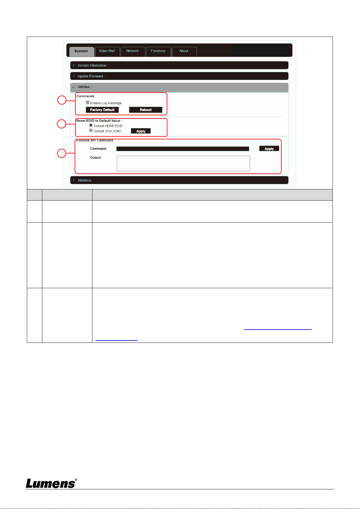
5.1.3 System - Utility Program
No
Item
Description
1
Commands
To restore the factory default settings of the device, please press [Factory Default]. If
you only need to restart the device (settings will not be reset), please press [Reboot].
2
Reset EDID to
Default Value
If the EDID data from the decoder is not compatible with the HDMI/VGA signal source,
please select the built-in HDMI EDID setting of the encoder (support 4K30 resolution,
including audio) or VGA EDID (support WUXGA resolution, excluding audio) setting to
solve the compatibility problem. Then, press [Apply].
<Remark> If restart the device, the EDID setting will be reset.
* The decoder operation interface does not have this function.
3
Console API
Command
To send a Telnet command to the device, enter the Telnet command in the Command
field, and then press [Apply]. The device’s response to the command will be showed on
the Output field.
<Remark> To check Telnet commands, please refer to OIP-D50E. D50D Telnet
Command List.
1
2
3
Dencoder
14
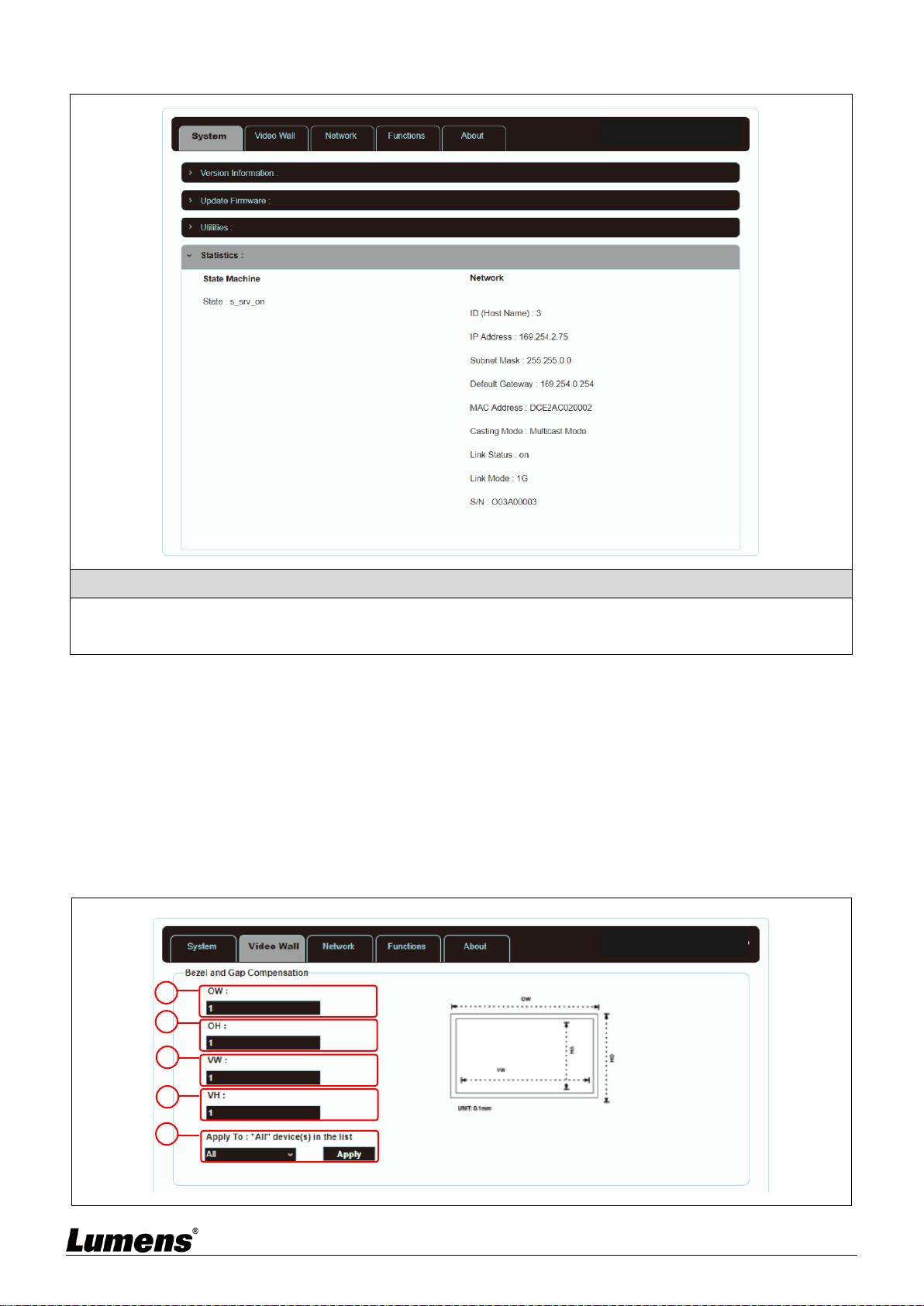
5.1.4 System - Statistics
Description
This window will display the current operating status of the device, including host name, network information, MAC
address, unicast or multicast, and connection status and mode.
5.1.5 Video Wall - Bezel and Gap Compensation
The video wall page can design, edit and operate a video wall built by displays connected with
multiple decoders. In the same video wall system, you can choose to control any decoder on
any encoder (as long as the channel number is shared), or you can choose to access the video
wall settings on the encoder and decoder. Some of the changed video wall settings can only be
applied to the decoder. After saving the new video wall settings, please set Apply To to select
the applied target and then press [Apply].
<Remark> Although it is feasible to build a small video wall with the unicast mode, it is strongly
recommended to give priority to adopt the multicast mode when building a video wall so that the network
bandwidth can be used more effectively.
1
2
3
4
5
Dencoder
Dencoder
15
Description
It provides the actual size setting of the display of the video wall. Various measurement units (inches, millimeters,
centimeters) will do, as long as all measurements are in the same unit and the numbers are integers.
<Remark> Video walls usually use the same type of displays in the same size. It is also feasible to use displays in
different sizes, as long as each display is measured in the same unit Video wall is laid out in the most common
rectangular pattern, and the bezels of each display are aligned with the center of the video wall.
No
Item
Description
1
OW
(OW) The horizontal size of the display.
2
OH
(OH) The vertical size of the display.
3
VW
(VW) The horizontal size of the signal source screen.
4
VH
(VH) The vertical size of the signal source screen.
5
Apply your
settings.
Set the device which you want to apply the changes to, and then press [Apply]
Select All: Apply the changes to all encoders and decoders in the current video wall.
Select This: Apply the changes to this device which is currently connecting to WebGUI.
Select a set of IP address on the Hosts end: Apply the changes to the encoder connected to
this address.
Select a set of IP address on the Clients end: Apply the changes to the decoder connected
to this address.
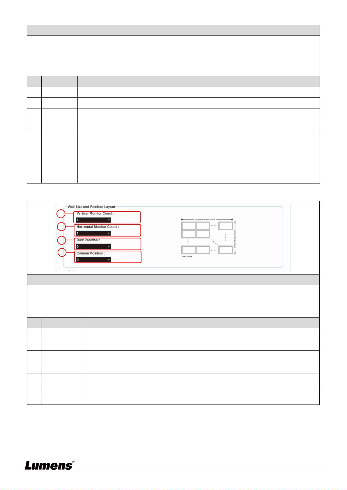
5.1.6 Video Wall - Wall Size and Position Layout
Description
Provide the amount of displays in the video wall and the position settings of displays. Typical video walls consist
of the same amount of displays in both horizontal and vertical directions (for example: 2 x 2 or 3 x 3). Through this
setting, you can build video walls in various rectangular pattern (for example: 5 x 1 or 2 x 3).
<Remark> The maximum amount of displays for both the horizontal and vertical directions is 8.
No
Item
Description
1
Vertical
Monitor
Amount
Set the amount of displays in the vertical direction of the video wall (up to 8).
2
Horizontal
Monitor
Amount
Set the amount of displays in the horizontal direction of the video wall (up to 8).
3
Row Position
Set the vertical position of the displays currently under control (from top to bottom,
ranges from 0 to 7).
4
Column
Position
Set the horizontal position of the displays currently under control (from left to right,
ranges from 0 to 7).
1
2
3
4
16
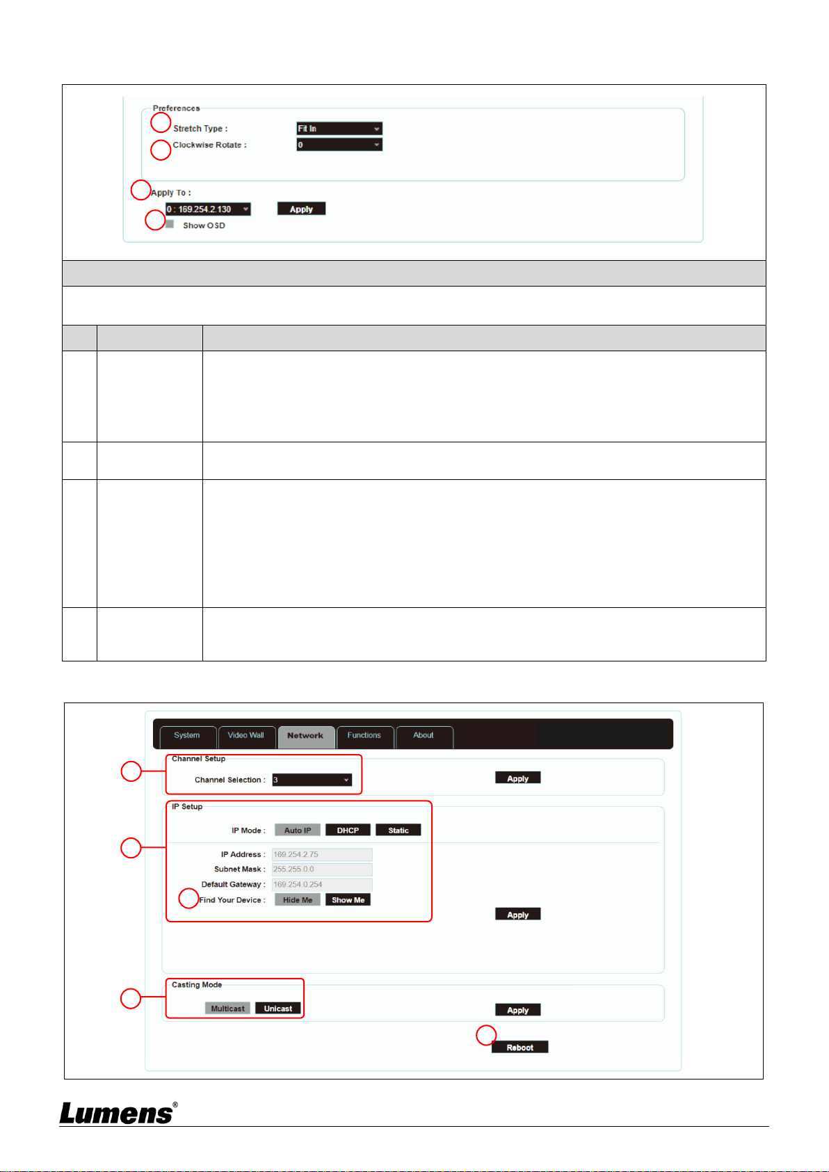
5.1.7 Video Wall - Preference
Description
It provides additional control to the video wall, including the screen display settings, and changes to applied
settings of the video wall.
No
Item
Description
1
Stretch Out
Set the stretch out mode of the screen.
- Fit In mode: The original aspect ratio of the image signal will be ignored, and the aspect
will be stretched to fit the size of the video wall.
- Stretch Out mode: The original aspect ratio of the image signal will be maintained, and
the screen will be zoomed in/out until it stretches for the four sides of the video wall.
2
Clockwise
Rotation
Set the rotation degree of the screen, which can be 0°, 180°, or 270°.
3
Apply your
settings
Set the encoder or decoder you want to apply the changes to, and then press [Apply]
Select All: Apply the changes to all encoders and decoders in the current video wall.
Select This: Apply the changes to this device which is currently connecting to WebGUI.
Select a set of IP address on the Hosts end: Apply the changes to the encoder connected
to this address.
Select a set of IP address on the Clients end: Apply the changes to the decoder
connected to this address.
4
Show OSD
(On Screen
Display)
Enable or disable the OSD of the currently selected channel.
5.1.8 Network
1
2
3
4
1
2
3
4
5
Dencoder

17
Description
Set the network control. After changing any settings, please press [Apply] and follow the instructions to restart the
device.
<Remark> If the IP address is changed, the IP address used to log in WebGUI must also be changed. If a new IP
address is assigned through Auto IP or DHCP, stop the image connection between the encoder and the decoder
to view the new IP address on the display connected to the decoder.
No
Item
Description
1
Channel
Setting
Select the broadcast channel of this device from the drop-down menu. As long as the
decoder channel is the same as the encoder in the same local area network, the encoder
signal can be received. There are a total of 0 to 255 channel numbers.
<Remark> Encoders in the same local area network must have different channel
numbers to avoid conflicts with each other.
2
IP Address
Setting
Select the IP mode and configuration of the device, and quickly search for the device.
- Auto IP mode: Automatically assign a set of APIPA address (169.254.XXX.XXX) to
itself.
- DHCP mode: Automatically obtain a set of address from the DHCP server.
- Static mode: Manually set the IP address, subnet mask, and default gateway.
Press [Apply] to save the new settings.
<Remark> The pre-set internet is Auto IP mode.
3
Search Your
Device
After pressing [Show Me], the indicators on the front panel of the device will flash
immediately for quick notice of the device.
After pressing [Hide Me], the indicators will back to normal.
It is very helpful for troubleshooting when a large number of devices are installed in the
cabinet.
4
Broadcasting
Mode
Click the button to select broadcast mode, and press [Apply] to save the new settings.
<Remark> The broadcast mode of the decoder must be the same as that of the encoder
to receive the signal.
- Multicast: Transfer the image stream of the encoder to multiple decoders at the same
time without increasing the bandwidth consumption. This mode is suitable for video wall
or matrix audio-visual distribution. It must be paired with a network switch that supports
IGMP Snooping.
<Remark> The built-in 3-port network switch in the decoder supports IGMP Snooping,
which can be used to distribute multicast VoIP streaming.
- Unicast: Transfer the image stream of the encoder to each decoder individually, so the
bandwidth consumption will be quite heavy. This mode is suitable for establishing simple
peer-to-peer streaming, and does not necessarily need to be paired with a network
switch that supports IGMP Snooping.
5
Restart
Press this button to restart the device.
18
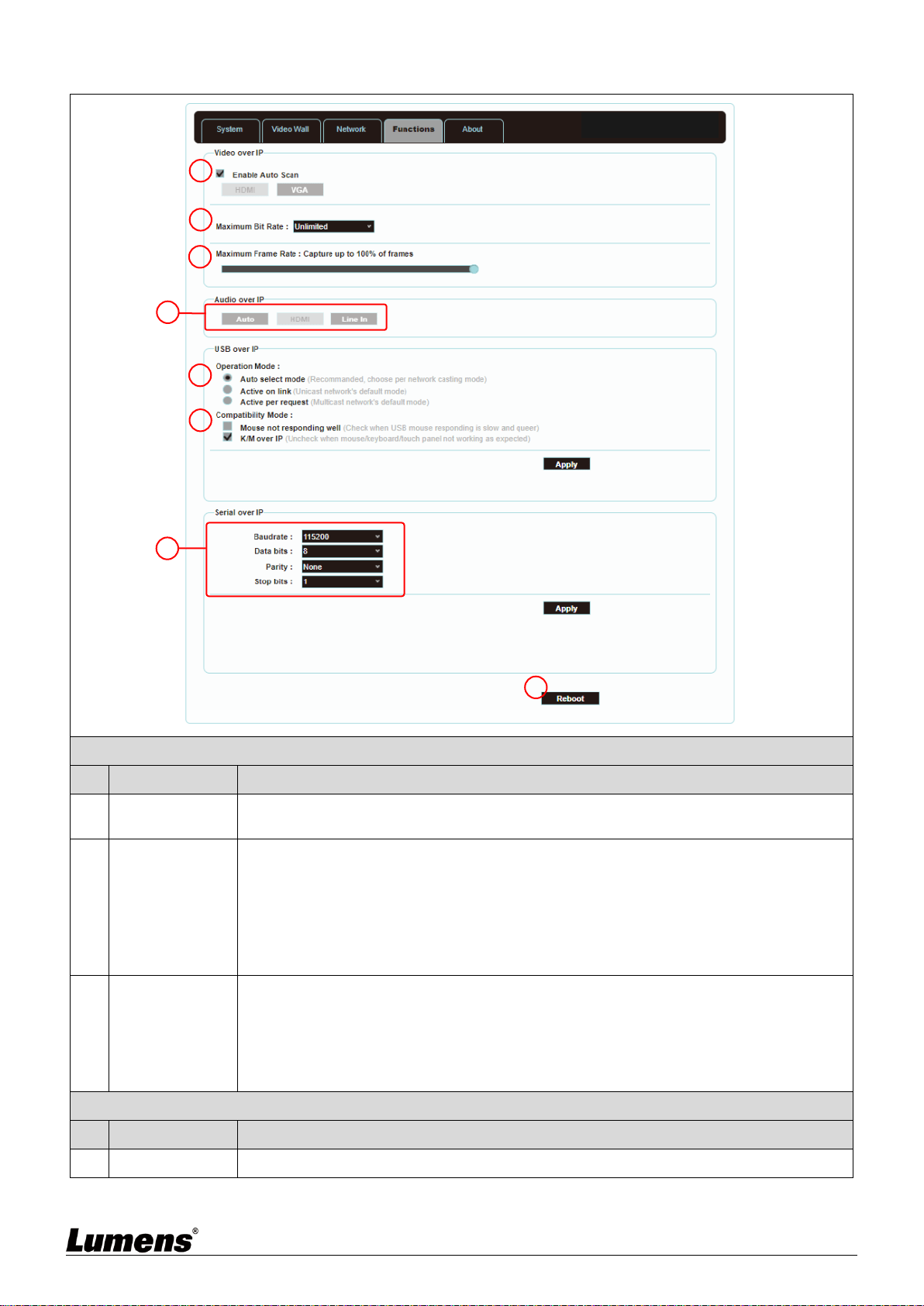
5.1.9 Functions - Image/Audio/USB/ Serial extension over IP (Encoder)
Image extension over IP
No
Item
Description
1
Select HDMI or
VGA Image
Switch to select HDMI or VGA input signal.
* The decoder does not support this function.
2
Maximum Bit
Rate
Set the maximum bit rate of the image stream. There are five options: Unlimited, 400
Mbps, 200 Mbps, 100 Mbps, and 50 Mbps.
Selecting Unlimited will use the maximum bit rate of the bandwidth to keep the update
frequency of the image stream intact.
<Remark> It is recommended to select Unlimited to transmit 4K image streams.
Bandwidth requirements will become very large, and the amount of image streams will
be limited.
3
Maximum
Frame Rate
Setting the encoding percentage of the image source (2% ~ 100%) can effectively
reduce the bandwidth requirement of high-resolution images. It is suitable for Power
Point presentations or digital signage displays, but not suitable for dynamic image
displays.
<Remark> If the frame rate of the dynamic images is too low, the frame will be
intermittent.
Audio extension over IP
No
Item
Description
4
Audio Mode
Extend the Audio signal over IP. There are three options: Auto, HDMI, and Line IN.
1
2
3
4
5
6
7
8
Dencoder
19
USB extension over IP
No
Item
Description
5
Operation Mode
Select the required USB operation mode to extend the USB signals. There are three
options: Auto select mode (automatic), Active on link (suitable for unicast), and Active
per request (suitable for multicast).
The default is Auto select mode, which can automatically select the correct USB
operation mode according to the broadcast mode of the encoder.
6
Compatibility
Mode
Select the required USB compatibility mode to enable the special optimization function
to solve the abnormal response of the mouse or touch screen.
Do not check this checkbox unless necessary.
Serial extension over IP
No
Item
Description
7
Serial
communication
settings
Manually set the baud rate, data bits, parity, and stop bits you need to extend RS-232
signals.
<Remark> The serial communication settings of the encoder and decoder must be the
same.
8
Restart
Press this button to restart the device.
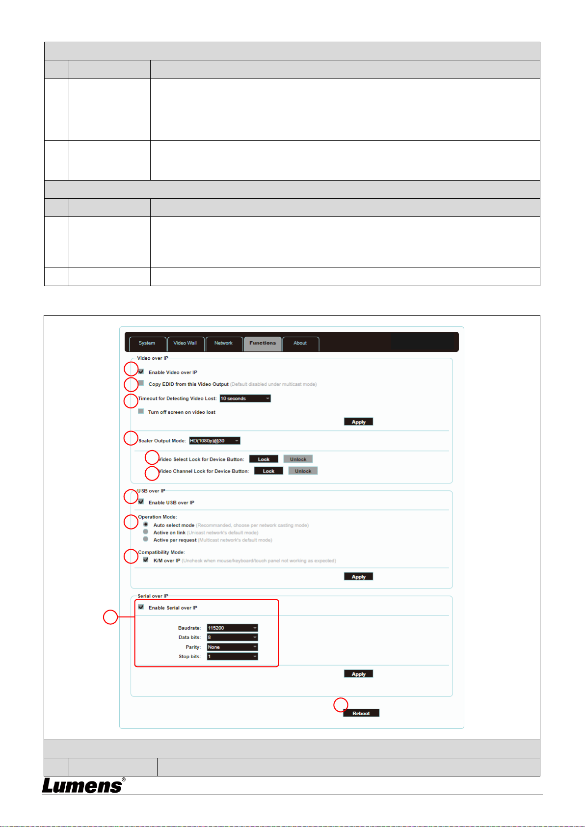
5.1.10 Functions - Image Signals /USB/Serial extension over IP (Decoder)
Image extension over IP
No
Item
Description
1
2
3
4
5
6
11
10
7
8
9
Encoder

20
1
Enable image
extension over IP
Uncheck to disable image signal extension over IP. Unless troubleshooting is in
progress, please check this checkbox.
2
Copy EDID data
After checking this checkbox with multicast, the EDID data of the device will be sent to
the connected encoder.
<Remark> This function can only be used in multicast mode.
3
Reminder for
disconnection
timeout
Select the waiting time when the signal source is lost from the drop-down menu, and a
Link Lost message will appear on the screen. There are seven options: 3 seconds, 5
seconds, 10 seconds, 20 seconds, 30 seconds, 60 seconds, or Never Timeout.
If you check and select Turn off screen, the device will stop sending any signal from
the HDMI output port after the waiting time expires.
4
Scaler output
mode
Select the output resolution from the drop-down menu.
Select one, and the output resolution will become the one you selected.
Select Pass-Through, the output resolution will be the signal source resolution. Select
Native, the output resolution will be up-converted to the connected display resolution.
5
Video
(VGA/HDMI)
Select Lock for
Device Button
After pressing [Lock], the video input selection button will be locked and cannot be
used.
6
Video channel
lock (CH+/-) for
device button
After pressing [Lock], the video channel selection button will be locked and cannot be
used.
USB extension over IP
No
Item
Description
7
Enable USB over
IP
Uncheck to disable USB over IP. Unless you do not use USB support, please check
this checkbox. Disabling this function can save a small amount of bandwidth.
8
Operation Mode
Select the required USB operation mode to extend the USB signals. There are three
options: Auto select mode (automatic), Active on link (suitable for unicast), and Active
per request (suitable for multicast).
The default is Auto select mode, which can automatically select the correct USB
operation mode according to the broadcast mode of the encoder.
9
Compatibility
Mode
Select the required USB compatibility mode to enable the special optimization function
to solve the abnormal response of the mouse or touch screen.
Do not check this checkbox unless necessary.
Serial extension over IP
No
Item
Description
10
Serial
communication
settings
Uncheck to disable Serial extension over IP. Unless you do not use serial support,
please check this checkbox. Disabling this function can save a small amount of
bandwidth.
Manually set the baud rate, data bits, parity, and stop bits you need to extend RS-232
signals.
<Remark> The serial communication settings of the encoder and decoder must be the
same.
11
Restart
Press this button to restart the device.
21
Chapter 6 KVM Function
6.1 KVM Descriptions
D50E encoder/D50D decoder provides the KVM function, which links HDMI signals with
USB signals through IP technology, and operates and controls remotely the keyboard,
screen image, displayed image, and mouse, making management and operation more
convenient.
6.2 KVM Operation
6.2.1 HDMI and USB need to be linked
When D50D decoder selects D50E encoder images on any node, connect the USB signals
between encoder/decoder at the same time
6.2.2 D50D decoder has a UI interface for easily operating KVM
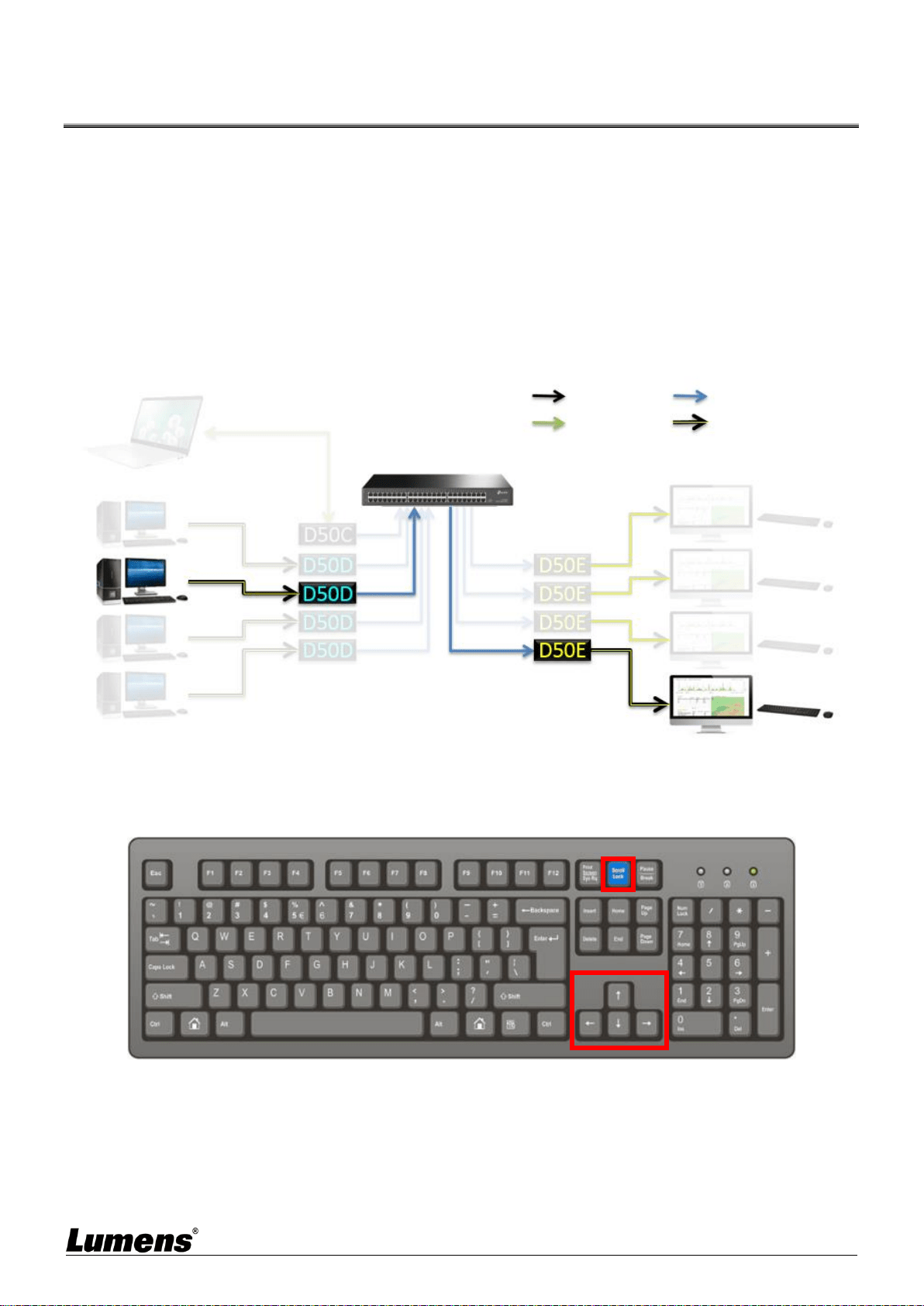
Method 1: Use the keyboard connected to the D50E encoder to control KVM OSD
[Scroll Lock] key to enable KVM OSD
When OSD appears, lock the arrow keys [↑] [↓] [←] [→] to operate the OSD
When OSD appears, use [↑] [↓] keys to operate OSD up/down and select the signal source
When OSD appears, switch the signal source 3 seconds after the up/down operation stops
or by pressing [→] key
When OSD appears, press [Scroll Lock] key or shut down KVM OSD after idling for 15
seconds and release the [↑] [↓] [←] [→] arrow keys to be regular keys
Control Path
Image Path
HDMI + USB
OIP URL
HDMI and USB signal linkage
HDMI and USB signal linkage

22
Method 2: Use the CH +/- buttons on the front panel of the D50D decoder host to select the
remote D50E encoder KVM (HDMI + USB)
Use (CH +) (CH -) buttons to enable KVM OSD
When OSD appears, use (CH +) (CH -) button to control OSD and select the signal source
When OSD appears, switch the signal source 3 seconds after (CH +) (CH -) key operation
stops
When OSD appears, shut down the KVM OSD after idling for 15 seconds

23
Chapter 7 Product Specification
7.1 Technical Specification
Item
Description of Specifications
D50E Encoder
D50D Decoder
HDMI
Bandwidth
340MHz/10.2Gbps
Audio-visual
Input Port
1x HDMI terminal
1x VGA terminal
1x 3.5 mm analog audio terminal
3x RJ-45 LAN terminal
1x 3.5mm microphone audio terminal
Audio-visual
Output Port
1x RJ-45 LAN terminal
1x 3.5mm analog audio terminal
1x HDMI terminal
1x VGA terminal
1x optical digital audio terminal
1x 3.5mm analog audio terminal
Data
Transmission
Port
1x IR extender [3.5mm terminal]
1x IR emitter [3.5mm terminal]
1 x RS-232 port [9-pin D-sub terminal]
1x USB Port [Type-B terminal]
1x IR extender [3.5mm terminal]
1x IR emitter [3.5mm terminal]
1 x RS-232 port [9-pin D-sub terminal]
4x USB Port [Type-A terminal]
IR
Frequency
30-50 kHz (30-60 kHz ideally)
Power
5 V/2.6 A DC
(US/EU standards and CE/FCC/UL
Certifications)
5 V/4 A DC
(US/EU standards and CE/FCC/UL
Certifications)
Statics
protection
Human Body Model:
±12 kV (Air Discharge)
±8 kV (Contact Discharge)
Size
231.5mm×25mm×108mm (W×H×D) [without parts]
231.5mm×25mm×120mm (W×H×D) [with parts]
Weight
660 g
666 g
Case material
Metal
Case color
Black
Operation
temperature
0˚C - 40˚C / 32˚F - 104˚F
Storage
temperature
−20˚C - 60˚C / −4˚F - 140˚F
Relative
humidity
20 - 90% RH (Non-condensing)
Power
consumption
7.15 W
17.68 W

24
7.2 Image Specification
Supported Resolutions (Hz)
Input Terminal
Output Terminal
HDMI
VGA
HDMI
VGA
640×480p@60
720×480p@59/60
720×576p@50
800×600p@60
1024×768p@60
1280×720p@50/59/60
1280×768p@60
1280×960p@60
1280×1024p@60
1440×480p@60
1440×576p@50
1366×768p@60
1600×1200p@60 (RB)
1920×1080p@24/25
1920×1080p@50/59/60
1920×1200p@60 (RB)
1920×1080i@50/59/60
3840×2160p@24/25/30
3840×2160p@50/60 (YUV 4:2:0)
4096×2160p@24/25/30
Note 1: HDMI input resolution can reach 4096 x 2160p@60 Hz (YUV 4:2:0).
Note 2: HDMI input resolution 4K@60 Hz (YUV 4:2:0) will be converted into 4K@30 Hz (RGB) output
resolution.
Note 3: VGA input and output resolution can reach 1920 x 1200@60 Hz (clock tick less than 150 MHz).
25
7.3 Audio Specification
Sound Effect Supported (kHz)
Input Terminal
Output Terminal
HDMI
HDMI
LPCM 2.0/5.1/[email protected]/88.2/176.4
LPCM 2.0/5.1/7.1@32/48/96/192
Standard Bitstream
Unicast Audio Transmission
Input Terminal
Output Terminal
HDMI IN
(EX)
LINE IN
(EX)
MIC IN
(DX)
HDMI
OUT(DX)
LINE OUT
(EX)
LINE OUT
(DX)
●
●
●
■
■
■
●
■
■
■
▲
■
▲
■
▲
■
●
■
▲
■
▲
■
Note: ● = HDMI digital audio. ■ = LINE analog audio. ▲ = microphone analog audio.
Multicast Audio Transmission
Input Terminal
Output Terminal
HDMI IN
(EX)
LINE IN
(DX)
MIC IN
(DX)
HDMI
OUT(DX)
LINE OUT
(EX)
LINE OUT
(DX)
●
●
●
■
■
■
●
■
■
■
▲
■
▲
■
■
●
■
▲
■
■
Note: ● = HDMI digital audio. ■ = LINE analog audio. ▲ = microphone analog audio.

26
Chapter 8 Troubleshooting
This chapter describes problems you may encounter while using OIP-D50E/D50D. If you have
questions, please refer to related chapters and follow all the suggested solutions. If the problem
still occurred, please contact your distributor or the service center.
No.
Problems
Solutions
1.
The signal source screen is
not shown on the display-end
1. Please check whether the Multicast of the encoder and
decoder is enabled:
(1) Enter the WebGUI control interface of the encoder and
decoder, and check whether the Casting Mode is Multicast on the
Network tab.
(2) Enter the WebGUI control interface of the D50C controller, then
click Device - [Settings] on the Encoder tab and Decoder tab to
check whether Multicast is enabled.
2. Make sure the source is set to HDMI or VGA:
(1) Enter the WebGUI control interface of the D50C controller, and
click Device - [Settings] on the encoder tab to check that the Video
type is set to HDMI or VGA
(2) On the front panel of the decoder host, press the Mode button
to switch between HDMI and VGA signal sources.
<Remark> You must choose the same signal source for the
encoder and decoder as HDMI or VGA. If they are not consistent,
the signal source screen will not be displayed.
2.
Image delay on the
display-end
1. Check whether the MTU of the encoder and decoder is
enabled (default is Enable):
Enter “GET_JUMBO_MTU” in the Command field in the WebGUI
interface system - Utility Program tab, and the Output below will
show whether the status of jumbo frame MTU is enabled or
disabled. If it is disabled, please enter “SET_JUMBO_MTU 1” in
the Command field to enable it, and follow the instructions to
restart the device to implement the changes.
2. The streaming mode may be Graphic Mode:
On the front panel of the decoder host, press the Mode button to
switch between the Video/Graphic modes. Please switch to the
Video mode.
3.
The image on the display-end
is broken or black
Check that the Jumbo Frame of the switch is set to above 8000;
Please make sure that IGMP Snooping of the switch and relevant
settings (Port, VLAN, Fast Leave, Querier) has been set to
“Enable”.
27
Chapter 9 Safety Instructions
Always follow these safety instructions when setting up and using this product:
1 Operation
1.1 Please use the product in the recommended operating environment, away from water or source of heat
1.2 Do not place the product on a tilted or unstable trolley, stand or table.
1.3 Please clean the dust on the power plug prior to usage. Do not insert the product’s power plug into a
multiplug to prevent sparks or a fire.
1.4 Do not block the slots and openings in the case of the product. They provide ventilation and prevent the
product from overheating.
1.5 Do not open or remove covers, otherwise it may expose you to dangerous voltages and other hazards.
Refer all servicing to licensed service personnel.
1.6 Unplug the product from the wall outlet and refer servicing to licensed service personnel when the following
situations happen:
If the power cords are damaged or frayed.
If liquid is spilled into the product or the product has been exposed to rain or water.
2 Installation
2.1 For security considerations, please make sure the standard hanging rack you bought is in line with UL or CE
safety approbations and installed by technician personnel approved by agents.
3 Storage
3.1 Do not place the product where the cord can be stepped on as this may result in fraying or damage to the
lead or the plug.
3.2 Unplug this product during thunderstorms or if it is not going to be used for an extended period.
3.3 Do not place this product or accessories on top of vibrating equipment or heated objects.
4 Cleaning
4.1 Disconnect all the cables prior to cleaning and wipe the surface with a dry cloth. Do not use alcohol or
volatile solvents for cleaning.
5 Batteries (for products or accessories with batteries)
5.1 When replacing batteries, please only use similar or the same type of batteries
5.2 When disposing of batteries or products, please adhere to the relevant instructions in your country or region
for disposing of batteries or products
Precautions
This symbol indicates that this equipment may
contain dangerous voltage which could cause
electric shock. Do not remove the cover (or back).
No user-serviceable parts inside. Refer servicing to
licensed service personnel.
This symbol indicates that there are
important operating and maintenance
instructions in this User Manual with this
unit.
FCC Warning
This equipment has been tested and found to comply with the limits for a Class B digital device, pursuant to part
15 of the FCC Rules. These limits are designed to provide reasonable protection against harmful interference in
a residential installation. This equipment generates, uses and can radiate radio frequency energy and, if not
installed and used in accordance with the instructions, may cause harmful interference to radio communications.
However, there is no guarantee that interference will not occur in a particular installation. If this equipment does
cause harmful interference to radio or television reception, which can be determined by turning the equipment off
and on, the user is encouraged to try to correct the interference by one or more of the following measures:
- Reorient or relocate the receiving antenna.
- Increase the separation between the equipment and receiver.
- Connect the equipment into an outlet on a circuit different from that to which the receiver is connected.
- Consult the dealer or an experienced radio/TV technician for help.
Notice :
The changes or modifications not expressly approved by the party responsible for compliance could void the
user’s authority to operate the equipment.
This equipment has been tested and found to comply with the limits for a Class B digital device, pursuant to part
15 of the FCC Rules. These limits are to provide reasonable protection from harmful interference in residential
installations.
IC Warning
This digital apparatus does not exceed the Class B limits for radio noise emissions
from digital apparatus as set out in the interference-causing equipment standard
entitled “Digital Apparatus,” ICES-003 of Industry Canada.
Cet appareil numerique respecte les limites de bruits radioelectriques applicables aux appareils numeriques de
Classe B prescrites dans la norme sur le material brouilleur: “Appareils Numeriques,” NMB-003 edictee par
l’Industrie.

28
Copyright Information
Copyrights © Lumens Digital Optics Inc. All rights reserved.
Lumens is a trademark that is currently being registered by Lumens Digital Optics Inc.
Copying, reproducing or transmitting this file is not allowed if a license is not provided by Lumens Digital Optics
Inc. unless copying this file is for the purpose of backup after purchasing this product.
In order to keep improving the product, the information in this file is subject to change without prior notice.
To fully explain or describe how this product should be used, this manual may refer to names of other products or
companies without any intention of infringement.
Disclaimer of warranties: Lumens Digital Optics Inc. is neither responsible for any possible technological,
editorial errors or omissions, nor responsible for any incidental or related damages arising from providing this file,
using, or operating this product.
