Loading ...
HARDWARE CONTAINED IN
PARTS BAG
(2) #6B sheet
metal nuts
A
(2) 5/16-18 x 3/4 hex
head cap screws
B
(2) 1/4-20 x 3 slotted round
head machine screws
C
(6) #6 flat
washers
D
©
(2) 1/4 flat
washers
E
(2) 1/4-20 spring
wing t_ggles
@
(4) #10-24
lock nuts
G
(8) #6AB x 1/4
phillips pan
head sheet
metal screws
I
(10) #IOAB x
5/8 phillips flat
head sheet
metalscrews
J
PREPARE HOOD
;J
(2) 5/16-18
locknu'ts
H
(2) #IOAB x 1-1/2
slottedpan head
sheet metalscrews
K
i
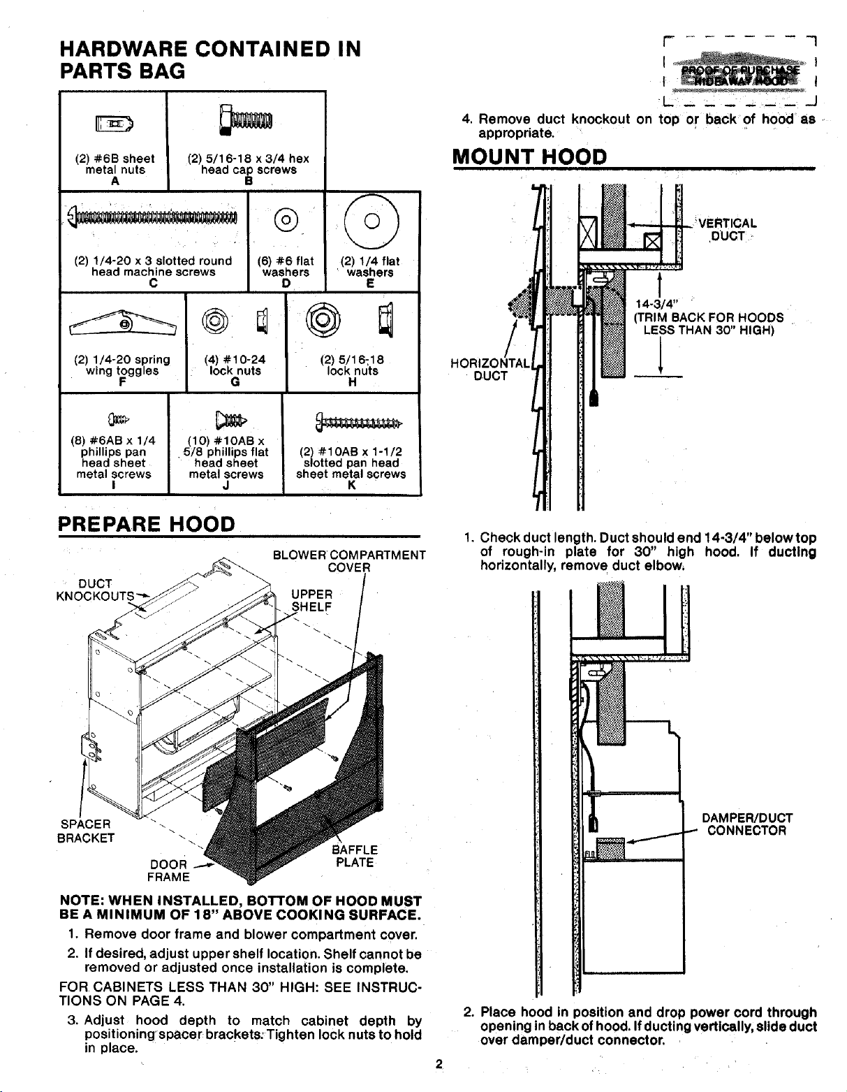
DUCT
BLOWER COM PARTMENT
COVER
UPPER
SHELF
SPACER
BRACKET
DOOR
FRAME
BAFFLE
PLATE
NOTE: WHEN INSTALLED, BOTTOM OF HOOD MUST
BE A MINIMUM OF 18" ABOVE COOKING SURFACE.
1. Remove door frame and blower compartment cover.
2. If desired, adjust upper shelf location. Shelf cannot be
removed or adjusted once installation is complete.
FOR CABINETS LESS THAN 30" HIGH: SEE INSTRUC-
TIONS ON PAGE 4.
3. Adjust hood depth to match cabinet depth by
positioningspacer brackets:Tighten lock nuts to hold
in place.
r I
I i
t I
4. Remove duct knockout on top or back of hood as
appropriate.
MOUNT HOOD
/
HORIZONTAl
DUCT
DUCT
t
14-3/4"
(TRIM BACKFOR HOODS
LESSTHAN 30" HIGH)
1. Check duct length. Duct should end 14-3/4" belowtop
of rough-in plate for 30" high hood. If ductlng
horizontally, remove duct elbow,
. _
FJ tl
I
!: j i
i
DAMPER/DUCT
.-.-. CONNECTOR
2. Place hood in position and drop power cord through
opening in back ofhood. If ducting vertically, slide duct
over damper/duct connector.
Loading ...
Loading ...
Loading ...