BHOAN
MODEL 113023
WARNING Z_
INTENDEDFOR DOMESTICCOOKINGONLY.
TO REDUCE THE RISK OF FIRE, ELECTRIC SHOCK, OR INJURY TO PERSONS,
OBSERVETHE FOLLOWING:
1. Use this unit only in the manner intended by the manufacturer. If you have
questions, contact the manufacturer at the address or telephone number listed
in the warranty.
2. Before servicing or cleaning unit, switch power off at service panel and lock the
service disconnecting means to prevent power from being switched on
accidentally. When the service disconnecting means cannot be locked, securely
fasten a prominent warning device, such as a tag, to the service panel.
3. lnstal[ationworkandelectricelwiringmustbedonebyaqualifiedperson(s) in
accordanqe with all applicable codes and standards, including fire-rated
construction codes and standards.
4. Sufficient air is needed for orocer combustion and _xhsustina nf oases thrmsnh
the flue (chimney) of fuel btJrni'ngequipment to prevent backc/'raft_ng. Foiiowthe
heating equipment manufacturer's guideline and safety standards such as
those published by the National Fire Protection Association (NFPA), and the
American Society for Heating, Refrigeration and Air Conditioning Engineers
(ASHRAE), and the local code authorities.
5. When cutting or drilling into wall or ceiling, do not damage electrical wiring and
other hidden utilities.
6. Ducted fans must always be vented to the outdoors.
7. Do not use this unit with an additional speed control device.
8. To reduce the risk of fire, use only metal ductwork.
9. Use with approved cord-connection kit only.
10. This unit must be grounded.
TO REDUCE THE RISK OF A RANGE TOP GREASE RRE:
1. Neverleavesurfaceunitsunattendedathighsattings. Boiloverscausesmoking
and greasy spillovers that may ignite.
2. Always turn hood ON when cooking at high heat or when cooking flaming foods.
3. Clean ventilating fans frequently, Grease should not be allowed to accumulate
on fan or filler.
4. Use proper pan size. Always use cookware appropriate for the size of the
surface element,
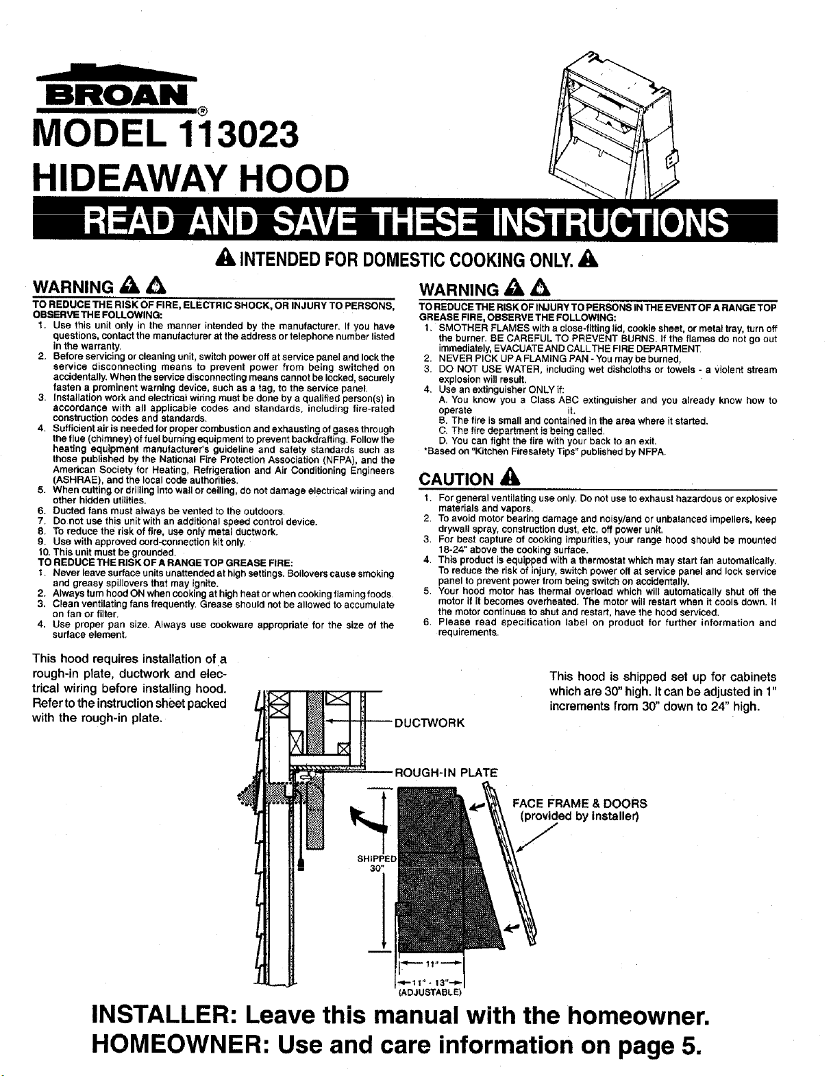
This hood requires installation of a
rough-in plate, ductwork and elec-
trical wiring before installing hood.
Refer to the instruction sheet packed
with the rough-in plate.
WARNING Z_ Z_k
TO REDUCE THE RISK OF INJURY TO PERSONS IN THE EVENT OF A RANGE TOP
GREASE FIRE, OBSERVE THE FOLLOWING:
1. SMOTHER FLAMES with a close-fitting lid, cookie sheet, or metal tray, turn off
the burner. BE CAREFUL TO PREVENT BURNS. If the flames do not go out
immediately, EVACUATEAND CALLTHE FIRE DEPARTMENT
2. NEVER PICK UP A FLAMING PAN - You may be burned.
3. DO NOT USE WATER, including wet dishcloths or towels - a Violent stream
explosion will result,
4. Use an extinguisher ONLY if:
A, You know you a Class ABC extinguisher and you already know how to
operate it.
B. The lire is small and contained in the area where it started.
C. The firedepartment isbeingca!!ed.
D. You can fightthe firewithyour back to an exit.
*Based on "Kitchen Firesalety Tips" published by NFPA.
CAUTION
1. Forgeneralventilating useonly. Donot use to exhaust hazardous or explosive
materials and vapors.
2. To avoid motor bearing damage and noisy/and or unbalanced impellers, keep
drywall spray, construction dust, etc. off power unit.
3. For best capture of cooking impurities, your range hood should be mounted
18-24" above the cocking surface.
4. This product is equipped with a thermostat which may start fan automatically.
To reduce the risk of injury, switch power off at service panel and lock service
panel to prevent power from being switch on accidentally.
5. Your hood motor has thermal overload which will automatically shut off the
motor if it becomes overheated. The motor will restart when it cools down. If
the motor continues to shut and restart, have the hood serviced.
6, Please read specification label on product for further information and
requirements.
IRK
This hood is shipped set up for cabinets
which are 30" high. It can be adjusted in 1"
increments from 30" down to 24" high.
SHIPPED
FACE FRAME & DOORS
(provided by installer)
J
(ADJUSTABLE)
INSTALLER: Leave this manual with the homeowner.
HOMEOWNER: Use and care information on page 5,
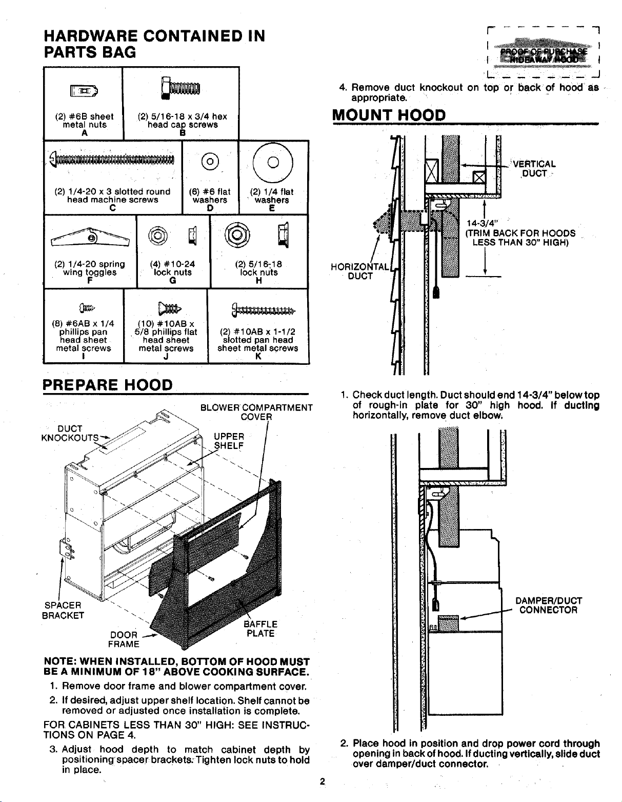
HARDWARE CONTAINED IN
PARTS BAG
(2) #6B sheet
metal nuts
A
(2) 5/16-18 x 3/4 hex
head cap screws
B
(2) 1/4-20 x 3 slotted round
head machine screws
C
(6) #6 flat
washers
D
©
(2) 1/4 flat
washers
E
(2) 1/4-20 spring
wing t_ggles
@
(4) #10-24
lock nuts
G
(8) #6AB x 1/4
phillips pan
head sheet
metal screws
I
(10) #IOAB x
5/8 phillips flat
head sheet
metalscrews
J
PREPARE HOOD
;J
(2) 5/16-18
locknu'ts
H
(2) #IOAB x 1-1/2
slottedpan head
sheet metalscrews
K
i
DUCT
BLOWER COM PARTMENT
COVER
UPPER
SHELF
SPACER
BRACKET
DOOR
FRAME
BAFFLE
PLATE
NOTE: WHEN INSTALLED, BOTTOM OF HOOD MUST
BE A MINIMUM OF 18" ABOVE COOKING SURFACE.
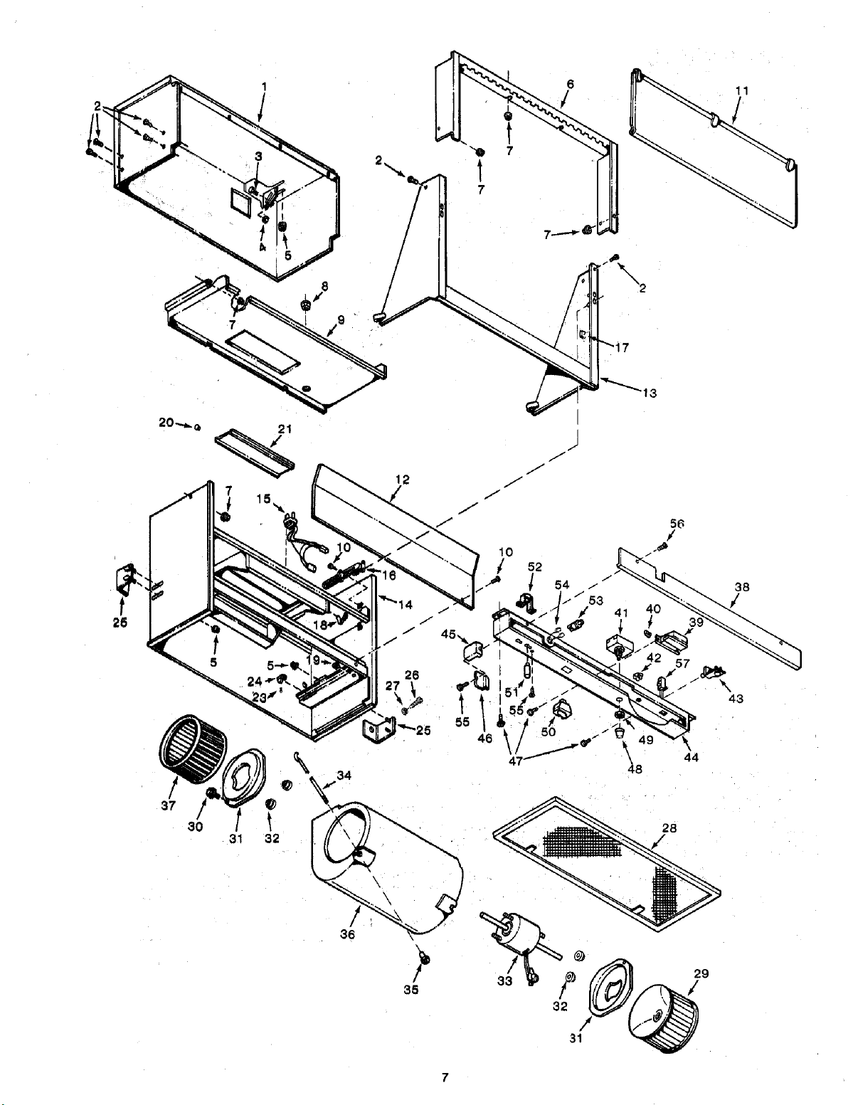
1. Remove door frame and blower compartment cover.
2. If desired, adjust upper shelf location. Shelf cannot be
removed or adjusted once installation is complete.
FOR CABINETS LESS THAN 30" HIGH: SEE INSTRUC-
TIONS ON PAGE 4.
3. Adjust hood depth to match cabinet depth by
positioningspacer brackets:Tighten lock nuts to hold
in place.
r I
I i
t I
4. Remove duct knockout on top or back of hood as
appropriate.
MOUNT HOOD
/
HORIZONTAl
DUCT
DUCT
t
14-3/4"
(TRIM BACKFOR HOODS
LESSTHAN 30" HIGH)
1. Check duct length. Duct should end 14-3/4" belowtop
of rough-in plate for 30" high hood. If ductlng
horizontally, remove duct elbow,
. _
FJ tl
I
!: j i
i
DAMPER/DUCT
.-.-. CONNECTOR
2. Place hood in position and drop power cord through
opening in back ofhood. If ducting vertically, slide duct
over damper/duct connector.
I(.) I(.)@
L
I(Q)@
-.,/
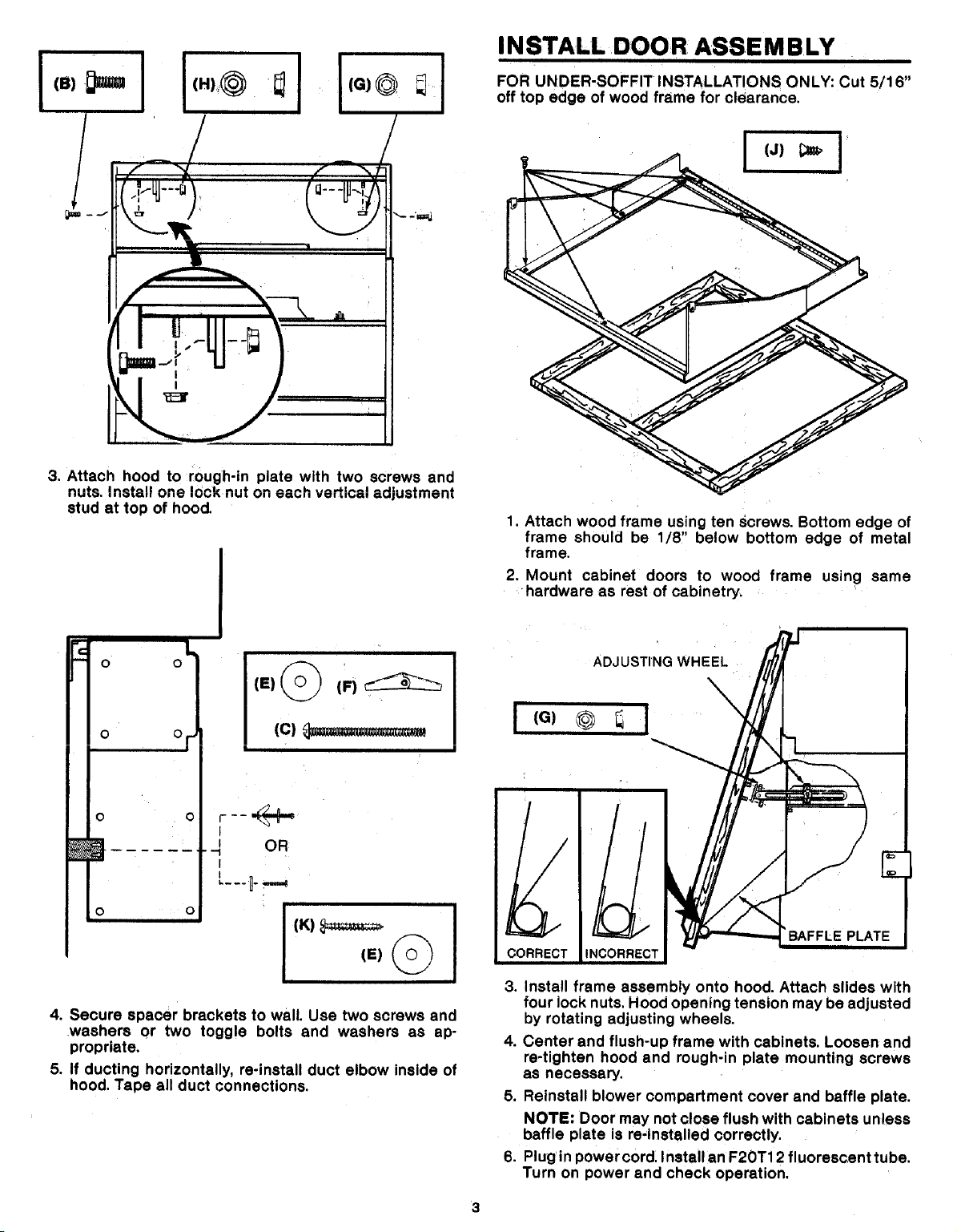
3. Attach hood to rough-in plate with two screws and
nuts. Install one lock nut on each vertical adjustment
stud at top of hood.
IN STALL DOO R ASSE M BLY
i
FOR UNDER,SOFFIT INSTALLATIONS ONLY: Cut 5/16"
off top edge of wood frame for clearance.
I (J)
1, Attach wood frame using ten screws. Bottom edge of
frame should be 1/8" below bottom edge of metal
frame.
2. Mount cabinet doors to wood frame using same
hardware as rest of cabinetry.
0 0
(E)_) (F)_
1C13==_=_=====_
|
I
d OR
I
4. Secure spacer brackets to wall. Use two screws and
washers or two toggle bolts and washers as ap-
propriate.
5. If ducting horizontally, re-install duct elbow inside of
hood. Tape all duct connections.
I
(G)
ADJUSTINGWHEEL
\
3. Install frame assembly onto hood. Attach slides with
four lock nuts, Hood opening tension may be adjusted
by rotating adjusting wheels.
4. Center and flush-u p frame with cabinets. Loosen and
re-tighten hood and rough-in plate mounting screws
as necessary.
5. Reinstall blower compartment cover and baffle plate.
NOTE: Door may not close flush with cabinets unless
baffle plate is re-Installed correctly.
6. Plug in powercord. Install an F2OT12 fluorescent tube.
Turn on power and check operation.
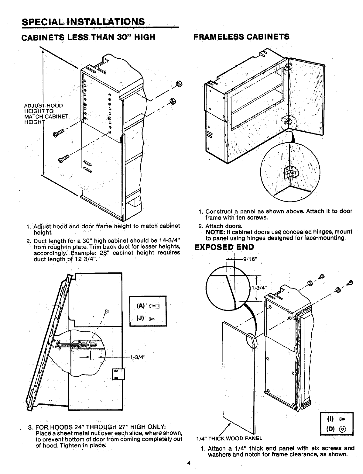
SPEC IAL IN STALLATI'O NS
CABINETS LESS THAN 30" HIGH
FRAM ELESS CABI N ETS
ADJUST HOOD
HEIGHT TO
MATCH CABINET
HEIGHT
1. AdjuSt hood and door frame height to match cabinet
height.
2. Duct length for a 30" high cabinet should be 14-3/4"
from rough, in plate. Trim back duct for lesser heights,
accordingly. Example: 28" cabinet height requires
duct length of 12-3/4".
314"
1. Construct a panel as shown above. Attach it to door
frame with ten screws.
2. Attach doors.
NOTE: If cabinet doors use concealed hinges, mount
to panel using hinges designed for face-mounting,
EXPOSED END
3. FOR HOODS 24" THROUGH 27" HIGH ONLY:
Place a sheet metal nut over each slide, where shown,
to prevent bottom of door from coming completely out
of hood. Tighten in place.
I
(I) o=_
(D) (_)
I
1/4" THICK WOOD PANEL
1. Attach a 1/4" thick end panel with six screws and
washers and notch for frame clearance, as shown.
USE AND CARE
OPERATION
Forbest results, alwaysturn on your hood before you begin
cooking. Let hood run for a few minutes after you turn off
range to allow hood to clear the air in the kitchen.
Pull out hood front to turn on blower and light. Light can
also be turned on when hood front Isclosed, The hood front
must be out and the speed control turned on for the blower
to start.
SPEED CONTROL
speeds and sound I_vels. 1"hecontrol turns the blower on
to high speed and dials down to low speeds,
With speed_control turned on, blower will start when hood
front is pulled out end will run at whatever previous speed
you have chosen,
HEAT SENTRY"
Your hood is equipped with a Heat SentryTM thermostat.This
thermostatis.s devicethat willturnon or speed up the blower
if it sensesexcessiveheat above the cookingsurface.
If blower Is not on, or if it is running at low speed, the Heat
Sentry" will override the normal blower control and turn
blower on to high speed. The blower will run until
tern peratures drop to normal levels. The blower will then
return to its original setting.
LIGHT
The light switch is located just to the left of the speed
control. Turn on light by pulling front of hood out or, If you
don't need the blower, just flip the switch for cooktop or
night-lighting,
CLEANING
Clean hood with a mild detergent suitable for painted
surfaces. DO NOT USE ABRASIVE CLOTH, STEEL WOOL
PADS OR SCOURING POWDERS.
To clean blower, remove blower compartment cover and
vacuum blower. Blower motor Is lifetime lubricated and
never needs oiling, Do not Immers+eblower In water.
FI LTE R
The aluminum filter in your hood should be cleaned
frequently with detergent to avoid grease buildu;). The
filter Is dishwasher safe. To remove filter, rotate retaining
clips on either side offilter opening out of the way and pull
filter out of hood.When replacing filter, make sure pulltabs
on filter aretoward bottom and to the back of hood.
SERVICE
CAUTION
l
ALWAYS DISCONNECT ELECTRIC POWER SUPPLY
TO HOOD BEFORE SERVICING. !
Your hood uses an F2OT12 fluorescenttube, available at
most hardware stores or home,centers.
If tube flickers or does not light,check the prongs on ends
oftube to make sure that they are properly seated in tube
holders. Slide prongs into holders and rotate tube so that
holders grip prongs and hold tube in place. If tube
continues to flicker or does not light, replace tube.
Ifends of the tube light but center does not,the starter may
be defective. Your hood uses an FS-2 starter, located on
underside of control unit. Remove old starter by pushing it
in and turning itcounterclockwise. Purchase a new starter
at your local hardware store or home center, and install it
by pushing it in and turning it clockwise.
If tube still does not light, order a 97007428 Ballast
Transformer Kit from your Broan Distributor or from the
Broan Service Department. W_ite Broan Mfg. Co., Inc., P.O.
Box 140, Hartford, WI 5.3027.
It_
BLOWER
KNURLED NUT_
HOW TO AVOID A COMMON RANGE-TOP GREASE FIRE
Your range hoodprovidesa protectivebarrierbetweenthe cook-
ing surfaceand the cabinets.
Keepfen, filters and grease ladensurfacesCLEAN accordingto
instructions.
• AlwaysturnhoodON whencookingat highheatto keep the cook_
mg area and the hoodcooler,
Use high heat settingsonlywhen necessary.
Never leave cookingsurface unattended.Boll-overcausessmok_'
ing and grea_;yspilloversthat may ignite.
Alwaysuse adequate-sized utensils.
If preparingflamingfoods, suchas CherriesJubilee, alwaysturn
hoodON toHIGH topreventa highheatsituationwhichcancause
damage or fire.
HOW TO EXTINGUISH A COMMON RANGE-TOP GREASE
FIRE
=,Neverplckupa flamingpan+lfdropped,flamescanspreedqulckly.
DO NOT USEWATER! A violentsteam explosionmay result.Wet
dishclothsor towelsare also dangerous.
i motherflames witha closefitting lid,cookiesheetor metaltray.
Flaminggreasecanalsobeexti.r_ulshedwithbakingsodaora multi-
purposedry chemicalextinguisher.
Turn off surfaceunits - if you can do sowithoutgettingburned.
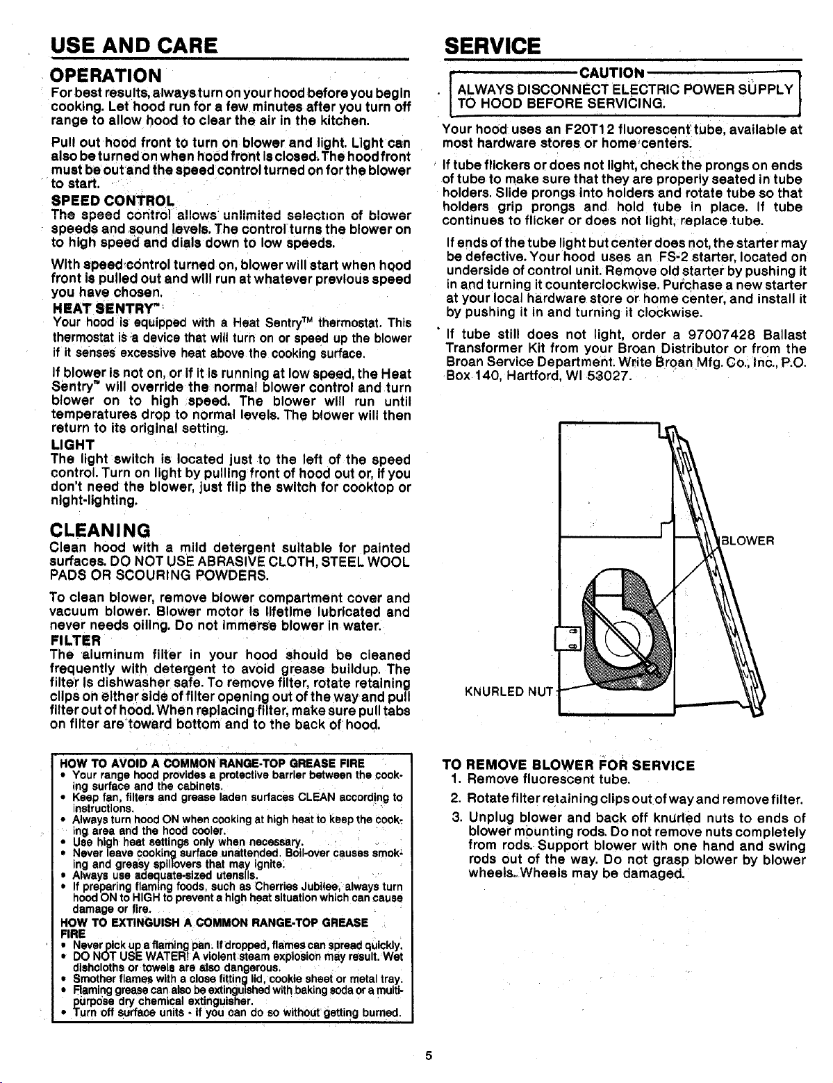
TO REMOVE BLOWER FOR SERVICE
1. Remove fluorescent tube.
2. Rotate filter retaining clips out ofway and remove filter.
3. Unplug blower and back off knUrled nuts to ends of
blower mounting rods. Do not remove nuts completely
from rods, Support blower with one hand and swing
rods out of the way. Do not grasp blower by blower
wheeis..Wheeis may be damaged,
SERVICE PARTS
........ -""I-" i .... -----TYT_---- _
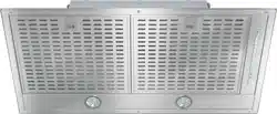
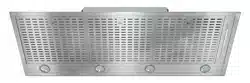
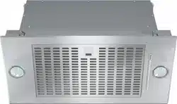
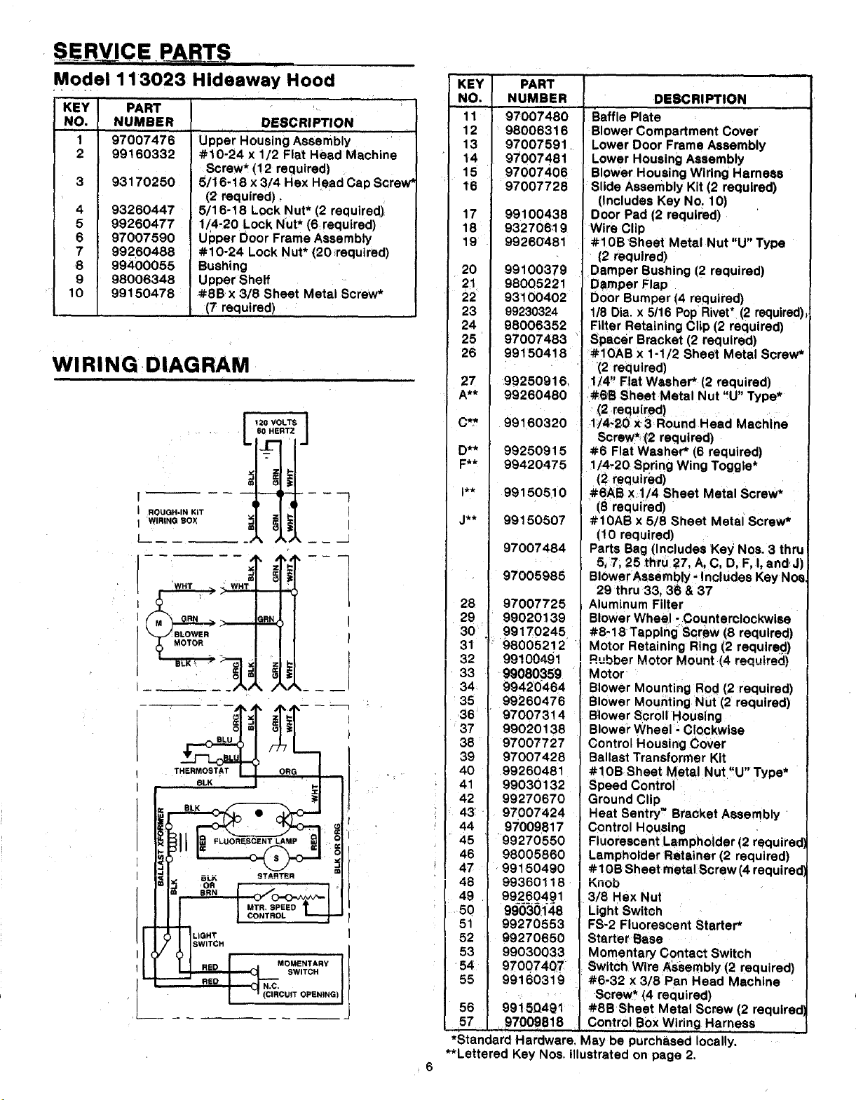
Model 113023 Hideaway Hood
KEY PART
NO. NUMBER
,,,,,,,
1 97007476
2 99160332
4
7
8
10
93170250
93260447
99260477
97007590
99260488
99400055
98006348
99150478
DESCRIPT!ON
upper Housing Assembly
#10-24 x 1/2 Flat Head Machine
Screw* (12 required)
5/16-18 x 3/4 Hex Head Cap screw _
(2 required)
5/16-18 Lock Nut* (2 required)
1/4.20 Lock Nut* (6 required)
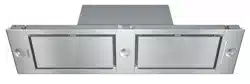
Upper Door Frame Assembly
# 10-24 Lock Nut* (20 required)
Bushing
Upper Shelf
#8Bx 3/8 Sheet Metal Screw*
(7 required)
WIRING DIAGRAM
L t2O VOLTS J
: ..... 60 HERTZ
[
I ROUGH-IN KIT II
I WIRING BOX _,
m
m w---}
I
I
WHT _ WHT
R _
:BLOWER
THERMOSTAT
,I oro
i =
tl
STARTER m
OR
BRN
-].G.T I
1SWITCH
I ' (CMRCU,TOPENING)I
KEY PART
NO. NUMBER
11 97007480
12 98006316
13 97007591
14 97007481
15 97007406
$6 97007728
17 99100438
18 932708;19
19 99260481
20 99100379
21 98005221
22 93100402
23 99230324
24 98006352
25 97007483
26 99150418
27 99250916
A** 99260480
C** 99160320
D** 99250915
F** 99420475
I** 991505.10
J** 99150507
97007484
97005985
28 97007725
29 99020139
30 99170245
31 98005212
_o oot_N_G1
33 99080359 •
34 99420464
35 99260476
36 97007314
37 99020138
38 ! 97007727
39 97007428
40 99260481
41 99030132
42 99270670
i _ 43: 97007424
44 94009817
45 99270550
46 98005860
47 99150490
46 99360118
49 99260491
50 99030148
51 99270553
52 99270650
53 99030033
54 97007407
55 99160319
56 99i5Q4_t
_700981S
DESCRIPTION
Baffle Plate
Blower Compartment Cover
Lower Door Frame Assembly
Lower Housing AsSembly
Blower Housing Wiring Harness
Slide Assembly Kit (2 required)
(Includes Key No. 10)
Door Pad (2 required)
Wire Clip
#10B Sheet Metal Nut "U" Type
(2 required)
Damper Bushing (2 required)
Damper Flap
Door Bumper (4 required)
1/8 Dia. x 5t16 Pop Rivet* (2 required)_
Filter Retaining Clip (2 required)
Spacer Bracket (2 required)
#10AB x 1-1/2 Sheet Metal Screw*
'(2 required)
1/4" Flat Washer* (2 required)
#_B Sheet Metal Nut "U" Type*
(2 required )
1;/4-20 x 3 Round Head Machine
Screw* (2 required)
#6 Flat Washer* (6 required)
1/4-20 Spring Wing Toggle*
(2 required)
#SAB xl/4 Sheet Metal Screw*
(8 required)
#10AB x 5/8 Sheet Metal Screw*
(10 required) . _
Parts Bag (Includes Key NOS. 3 thru!
5_7, 25 thru 27, A, C, D, F, I, and J)
BI0wer AssemblY - Includes Key Nos!
29 thru 33, 36 & 37
Aluminum Filter
Blower Wheel - Counterclockwise
#8-18 Tapping Sarew (8 requ red)
Motor Retaining Ring (2 required )
Rubber Motor Mount (4 required)
Motor
Blower Mounting Rod (2 required)
Blower Mounting Nut(2 required)
Blower Scroll Housing
Blower Wheel - Clockwise
Control Housing Cover
Ballast Transformer Kit
#!OB Sheet Metal Nut "U" Type*
Speed Control
Ground Clip
Heat Sentry" Bracket Assembly
Control Housing
Fluorescent Lampholder (2 requirec
Lampholder Retainer (2 required)
#10B Sheet metal Screw (4 required'
Knob
3/8 Hex Nut
Light Switch
FS-2 Fluorescent Starter*
Starter Base
Momentary Contact Switch
Switch Wire Assembly (2 required)
#6-32 x 3/8 Pan Head Machine
Screw, (4 required)
#SB Sheet Metal Screw (2 require¢
Control.Box Wiring Harness
*Standard Hardware. May be purchased locally.
**Lettered Key Nos. illustrated on page 2.
6
11
8
\
@
37 @
30 l
31 32
34
\
\
!
12
36
35
32
31
44
28
/
29
38
43
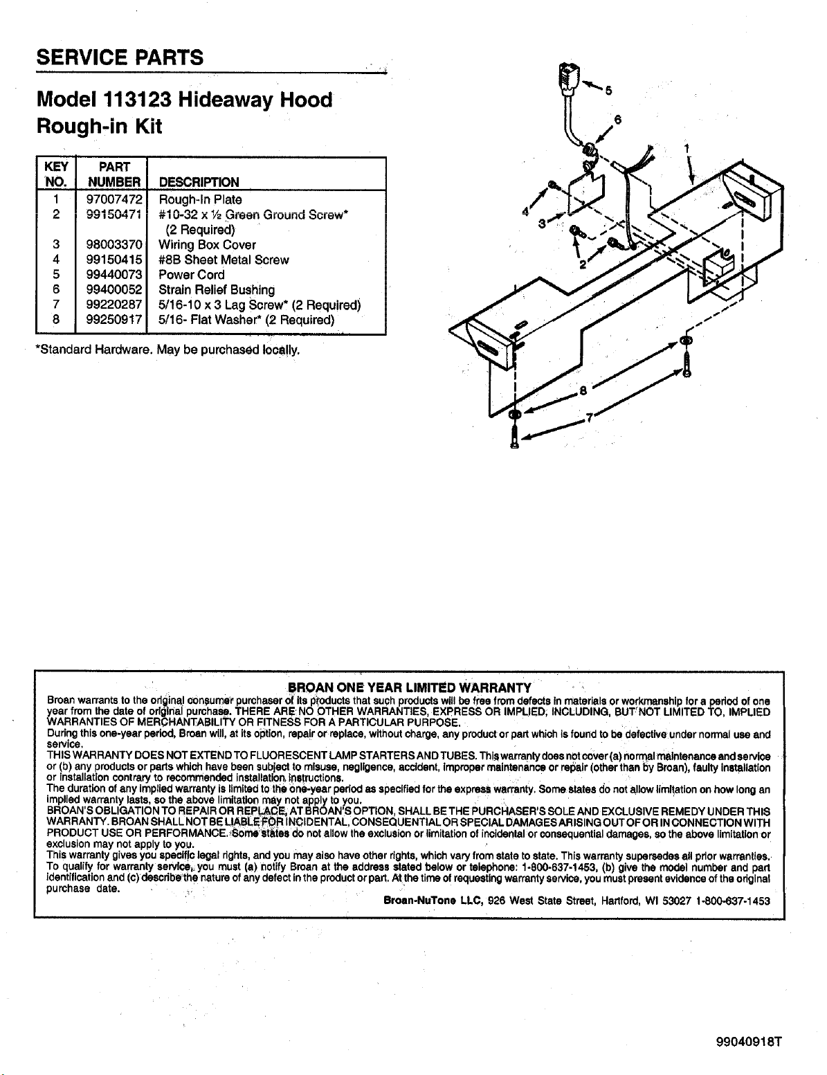
SERVICE PARTS
Model 113123 Hideaway Hood
Rough-in Kit
KEY PART
NO. NUMBER
1 97007472
3
4
5
6
7
8
98003370
99150415
99440073
99400052
99220287
99250917
*Standard Hardware.
DESCRIPTION
Rough-InPlate
I U'O_'_ X /2 _lUt:_ll _IUUIIU OUlrc_W
(2 Required)
Wiring Box Cover
#8B Sheet Metal Screw
Power Cord
Strain Relief Bushing
5/16-10 x 3 Lag Screw* (2 Required)
5/16- Flat Washer* (2 Required)
Maybe purchasedlocally.
BROAN ONE YEAR LIMITED WARRANTY
Broan warrants to the origins!!consumer purchaserof its p_'oductsthat such productswill be free from defects inmaterials orwork_ nship for a period of one
year from the date of original pumhase. THERE ARE NO OTHER WARRANTIES, EXPRESS OR IMPLIED. INCLUDING, BUT NOT LIMITED TO. IMPLIED
WARRANTIES OF MERCHANTABILITY OR FITNESS FOR A PARTICULAR PURPOSE,
Duringthis one-year period, Broan will,at its option, repair or replace, withoutcharge, any productor partwhichis foundto be defectiveunder normal use and
service.
THIS WARRANTY DOES NOT EXTEND TO FLUORESCENT LAMP STARTERS AND TUBES. Thiswarrantydoes notcover (a) normalmaintenance and servise
or (b) any 0roductsor parts whichhave been subject tomisuse, negligence, accident, impropermaintenance or repair (otherthan r0yBroan), faultyinstallation
or installationcontrary to recommended installation,instructions.
The duration of any implied warranty is limitedto the one-year periodas specifiedfor the express warranty. Some states do not allow limitationon how long an
implied warranty lasts, so the above limitationmay not apply to you.
BROAN'S OBLIGATION TO REPAIR OR REPL_C_ AT BROAN'S OPTION, SHALL BE THE PURCHASER'S SOLE AND EXCLUSIVE REMEDY UNDER THIS
WARRANTY. BROAN SHALL NOT BELIABLE:FOR INCIDENTAL CONSEQUENTIAL OR SPECIAL DAMAGES ARISING OUT OFOR INCONNECTION WITH
PRODUCT USE OR PERFORMANCE.,_ome st_es do notallow the exclusionor limitation of incidentalorconsequential damages, so the above limitation or
exclusion may not apply to you.
This warranty givesyou specificlegal rights,and you may also have other rights,which vary from state to state. This warranty supersedesall priorwarranties,
To qualify for warranty servioe_you must (a) notify Broan at the address stated below or telephone: 1-800-637-1453 b) give the model number and pan
identification and (c)describethe natureof any defect inthe productorpart. Atthe t me of requestingwarrantyservice,you mustpresent evidence of the odglnal
purchase date.
Broen-NuTone LLC, 926 West State Street. Hartford. WI 53027 1-800-637-1453
99040918T