Loading ...
Loading ...
Loading ...

English
8
Storage Recommendations
1. The best storage place is one that is cool and dry, away
from direct sunlight and excess heat orcold.
2. For long storage, it is recommended to store a fully
charged battery pack in a cool dry place out of the
charger for optimalresults.
nOTE: Battery packs should not be stored completely
depleted of charge. The battery pack will need to be
recharged beforeuse.
SAVE THESE INSTRUCTIONS FOR
FUTURE USE
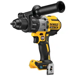
Intended Use
Your drill/driver/hammerdrill is designed for professional
drilling, screwdriving and percussion drillingapplications.
DO nOT use under wet conditions or in presence of
flammable liquids orgases.
Your drill/driver/hammerdrill is a professional power tool.
DO nOT let children come into contact with the tool.
Supervision is required when inexperienced operators use
thistool.
Belt Hook and Bit Clip
(Optional Accessories, Fig.A)
WARNING: To reduce the risk of serious personal
injury, turn unit off and remove the battery pack
before making any adjustments or removing/
installing attachments or accessories. An
accidental start-up can causeinjury. Exception—
Tool Connect™ functions and mode adjustments
require battery to beinstalled.
WARNING: To reduce the risk of serious personal
injury, ONLY use the tool's belt hook to hang the
tool from a work belt. DO NOT use the belt hook
for tethering or securing the tool to a person or object
during use. DO NOT suspend tool overhead or suspend
objects from the belthook.
WARNING: To reduce the risk of serious personal
injury, ensure the screw holding the belt hook
issecure.
CAUTION: To reduce the risk of personal injury or
damage, DO NOT use the belt hook to hang the
drill while using as aspotlight.
iMPORTAnT: When attaching or replacing the belt hook
7
or bit clip
9
, use only the screw
8
that is provided. Be sure
to securely tighten thescrew.
The belt hook
7
and bit clip
9
can be be attached to
either side of the tool using only the screw
8
provided, to
accommodate left- or right- handed users. If the hook or bit
clip is not desired at all, it can be removed from thetool.
To move belt hook or bit clip, remove the screw
8
that
holds it in place then reassemble on the opposite side. Be
sure to securely tighten thescrew.
Variable Speed Trigger Switch (Fig.A)
To turn the tool on, squeeze the trigger switch
1
. To turn
the tool off, release the trigger switch. Your tool is equipped
with a brake. The chuck will stop as soon as the trigger
switch is fullyreleased.
nOTE: Continuous use in variable speed range is not
recommended. It may damage the switch and should
beavoided.
Side Handle (Fig.A)
WARNING: To reduce the risk of personal injury,
ALWAYS operate the tool with the side handle
properly installed. Failure to do so may result in
the side handle slipping during tool operation and
subsequent loss of control. Hold tool with both hands
to maximizecontrol.
Side handle
13
clamps to the front of the gear case and
may be rotated 360° to permit right- or left-hand use. Side
handle must be tightened sufficiently to resist the twisting
action of the tool if the accessory binds or stalls. Be sure to
grip the side handle at the far end to control the tool
during astall.
Forward/Reverse Control Button (Fig.A)
A forward/reverse control button
2
determines the
direction of the tool and also serves as a lock-offbutton.
To select forward rotation, release the trigger switch and
depress the for ward/re verse control button on the right side
of thetool.
To select reverse, release the trigger switch and depress the
forward/reverse control button on the left side of thetool.
The center position of the control button locks the tool in
the off position. When changing the position of the control
button, be sure the trigger isreleased.
nOTE: The first time the tool is run after changing the
direction of rotation, you may hear a click on start up. This is
normal and does not indicate aproblem.
Torque Adjustment (Fig.C–E)
Your tool has an electronic adjustable torque screwdriver
system for driving and removing a wide array of fasteners.
Circling the torque adjustment collar
3
are numbers, a
drill bit symbol and a hammer symbol. These numbers
are used to set the clutch to deliver a torque range. The
higher the number on the collar, the higher the torque and
the larger the fastener that can be driven. To select any of
the numbers, rotate until the desired number aligns with
thearrow.
Bind-Up Control®
WARNING: When Bind-Up Control® is disabled
and the torque adjustment collar is in the drill or
hammerdrill position, the drill will not clutch. The drill
may stall if overloaded, causing a suddentwist.
The DCD997C is equipped with a Bind-Up Control® system.
This feature limits the tool output torque in drill and
hammerdrill positions only. If the Bind-Up Control® system
activates, the drill torque will drop and the tool will give a
buzz sensation. Just release the trigger to restart the drill.
The Bind-Up Control® system setting is preset to ENABLED
for Home and Modes 1–3 at the factory. Modes 1–3 can be
enabled/disabled using the Tool Connect™ app. Refer to
Table 1 for factorypresets.
Loading ...
Loading ...
Loading ...