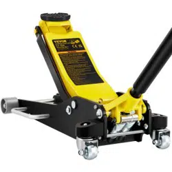

HYDRAULIC FLOOR JACKS

This is the original instruction, please read all manual instructions carefully before operating.
VEVOR resees clear interpretation of our user manual. The appearance of the product shall
be subject to the product you received. Please forgive us that we won't inform you again if
there is any technology or software updates on our product.
HYDRAULIC
FLOOR JACKS
Instruction Manual
01
WARNING: The jack must be used only on hard level suaces and be free to roll during lifting and
lowering. Do not get under a vehicle that is suppoed only by a trolley jack-use suppo stands.
CAUTION: Carefully read instructions and procedures for safe operations.
INSPECTIONS
1. Before Each Use
Visual inspection should be made before each use of the garage jack for abnormal conditions such as
cracked welds, leaks and damaged, loose, or missing pas.
2. After Each Use
The garage jack should be inspected immediately if the lift is believed to have been subjected to an abnormal
load or shock. It is recommended that inspection be made by manufacturer’s or supplier’s authorised repair
facility.
RECOMMENDATION FOR SAFE USAGE OF THE JACK
• The jack should be used on a hard level suace and be free to roll during lifting and lowering.
• The unlifted wheels of the vehicle should be chocked.
• The load should be centrally located on the head cap.
• No person should remain in a vehicle that is being lifted.
• The jack should be used for lifting and lowering only;
the raised vehicle should be suppoed on vehicle suppo stands.
• No person should get their body under a vehicle that is suppoed only by a hydraulic trolley jack.
• The vehicle manufacturer owner’s manual should be consulted prior to the lifting of the vehicle.
• Make sure that lift point is stable and properly centered on head cap.
CAUTION BEFORE USING
Due to shipment and/or handling air can be trapped in the hydraulic system, which can inteere with the
jacks lifting. To release air from the hydraulic system:
• Open release valve by turning the jack handle counterclockwise.
• Remove the oil ller plug from the cylinder.
• Rapidly pump jack handle through several full strokes.
• Replace the oil ller plug into the cylinder.
WARNING
• The unlifted wheels of the vehicle should be chocked.
• The load should be centrally located on the head cap.
• No person should remain in a vehicle that is being lifted.
• The vehicle manufacturer owner’s manual should be consulted prior to lifting of the vehicle.
• The hydraulic trolley jack should be used for lifting and lowering only. And it can not be used as a
suppo tool.
SAFE INSTRUCTIONS
02
03
SET UP - BEFORE USE
WARNING: Read the ENTIRE IMPORTANT SAFETY INFORMATION section at the beginning of this
manual including all text under subheadings therein before set up or use of this product.
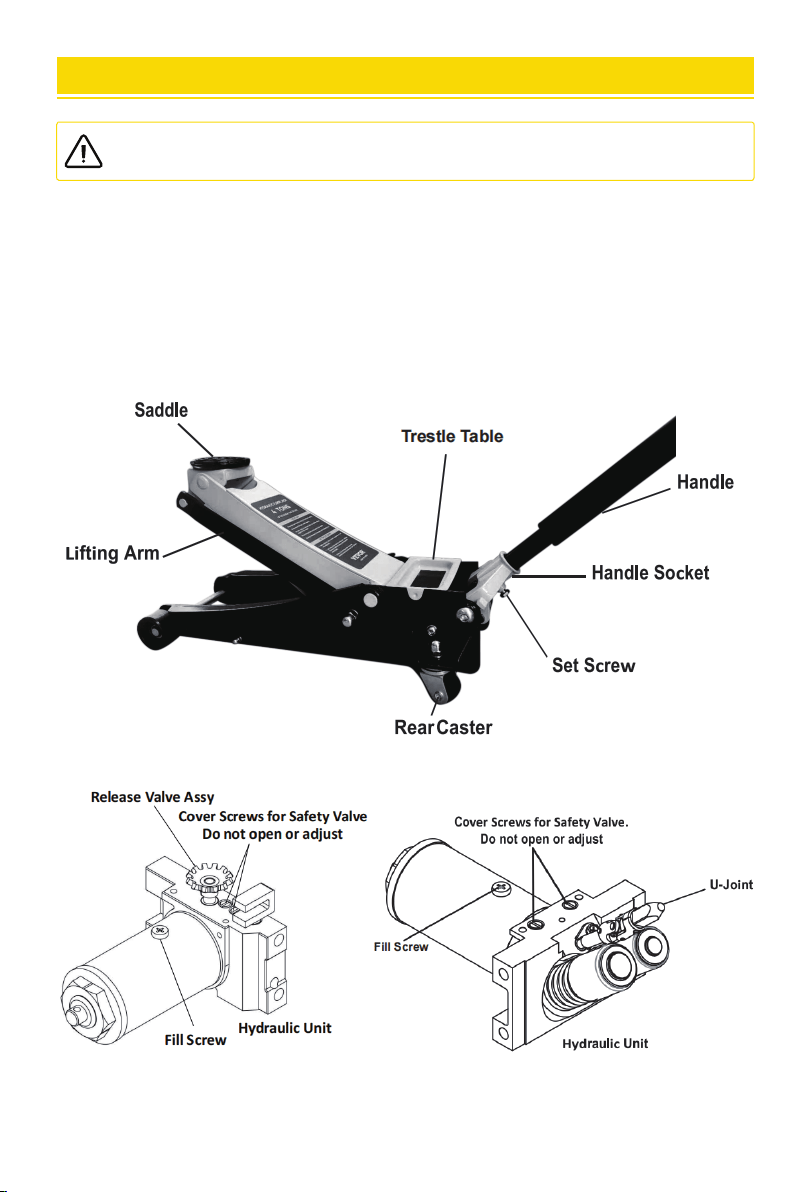
ATTACHING THE HANDLE
FUNCTIONS
• Attach the Upper Handle to the Lower Handle.
• Loosen the Set Screw and inse the assembled Handle into the Handle Socket.
• Tighten the Set Screw.
WARNING: Read the ENTIRE IMPORTANT SAFETY INFORMATION section at the beginning of this
manual including all text under subheadings therein before set up or use of this product.
OPERATING INSTRUCTIONS
BLEEDING
LIFTING
BEFORE EACH USE OR IF JACK PERFORMANCE DECREASES
check for excessive air and proper hydraulic uid level in Jack. If Jack appears not to be working properly, it
may be necessa to purge its hydraulic system of excessive air as follows:
04
1. Loosen the Set Screw.
2. Loosen the Fill Screw.
3. Check uid level and, if necessa, top o by adding Hydraulic Fluid as show below.
4. Twist the Handle clockwise to the tightest position to close the Valve, then pump the Handle several times
quickly.
5. Replace Fill Screw.
IMPORTANT: After bleeding the Jack, test the Jack for proper operation prior to its actual use.
6. If, after bleeding, the Jack does not appear to be working properly, do not use it until repaired by a qualied
seice technician.
ADDING HYDRAULIC FLUID
1. Remove the Fill Screw. Do not remove or loosen Safety Valve Cover Screws.
2. Add high grade hydraulic uid (sold separately) slowly until the uid reaches 1/4″ below the top of the Fill Po.
Note: Do not touch the handle when adding hydraulic uid.
3. Replace Fill Screw.
WARNING: Park vehicle on a at, level, solid, suace safely away from oncoming trac. Turn o
the vehicle’s engine. Place the vehicle’s transmission in “PARK” (if automatic) or in its lowest gear
(if manual). Set the vehicle’s emergency brake. Then chock the wheels that are not being lifted.
1. Slowly twist the Handle counterclockwise to lower the Jack. Once the Jack is fully lowered, twist the Handle
clockwise to the tightest position to close the Valve.
2. Carefully position the Jack’s Saddle under the vehicle manufacturer’s recommended lifting point.
(See vehicle manufacturer’s owner’s manual for location of frame lifting point.)
3. Pump the Handle until the top of the Saddle has nearly reached the vehicle’s lifting point.
Position the Saddle directly under the vehicle’s lifting point.
4. To lift the vehicle, pump the Handle. Use smooth, full strokes.
5. Select matching jack stands (sold separately) of appropriate capacity. Set the jack stands to the same height
according to the manufacturer’s instructions, making sure they lock securely into position.
6. Position the jack stands’ saddles under the vehicle manufacturer’s recommended suppo points.
WARNING! Ensure that the vehicle suppo points are fully seated in the saddles of both jack stands.
Use a matched pair of jack stands per vehicle to suppo one end only.
7. Slowly twist the Handle counterclockwise to lower the vehicle onto the jack stands’ saddles.
8. Once the vehicle is fully seated on the jack stands, continue slowly lowering the Jack until it is completely
lowered.
9. Remove the Jack and store safely out of the way.
MAINTENANCE AND SERVICING
LOWERING
1. Carefully remove all tools, pas, etc., from under the vehicle.
2. Position the Jack’s Saddle under the lifting point. Turn the Handle rmly clockwise and raise vehicle high
enough to clear the jack stands.
3. Carefully remove the jack stands.
4. Slowly turn the Handle counterclockwise to lower the vehicle onto the ground.
5. Lower the Jack completely. Store the Jack indoors out of children’s reach.
05
WARNING: Procedures not specically explained in this manual must be peormed only by a
qualied technician.
WARNING: TO PREVENT SERIOUS INJURY FROM TOOL FAILURE: Do not use damaged equipment.
If abnormal noise or vibration occurs, have the problem corrected before fuher use.
CLEANING, MAINTENANCE, AND LUBRICATION
1. BEFORE EACH USE, inspect the general condition of the Jack. Check for:
• loose hardware,
• misalignment or binding of moving pas,
• cracked or broken pas,
• any condition that may aect its safe operation.
2. BEFORE EACH USE, thoroughly test the Jack for proper operation prior to its actual use.
If the Jack appears not to be working properly, follow Bleeding instructions on page 4.
3. AT LEAST ONCE EVERY THREE YEARS, change the hydraulic uid:
• With the Jack fully lowered, remove the Fill Screw.
• Tip the Jack over to allow the old hydraulic uid to drain out completely.
Dispose of the old hydraulic uid in accordance with local regulations.
• With the Jack upright, completely ll the Hydraulic Unit with high grade hydraulic uid until the uid is
1/4″ below the top of the Fill Po.
• Turn the Handle counterclockwise to open the Release Valve.
• Pump the Handle up and down quickly several times to purge air from the system.
• Recheck uid level and re-ll as needed.
• Replace the Fill Screw.
4. AFTER EACH USE, wipe with a clean cloth. Store the Jack indoors out of children’s reach.
POSSIBLE SYMPTOMS
PROBABLE SOLUTION
(Make ceain that the Jack is not suppoing
a load while attempting a solution.)
Jack will
not lift at
its weight
capacity
TO PREVENT SERIOUS INJURY:
Use caution when troubleshooting a malfunctioning jack. Stay well clear of the suppoed load. Completely
resolve all problems before use. If the solutions presented in the Troubleshooting guide do not solve the
problem, have a qualied technician inspect and repair the jack before use. After the jack is repaired: Test it
carefully without a load by raising and lowering it fully, checking for proper operation,
BEFORE RETURNING THE JACK TO OPERATION.
WARNING
TROUBLESHOOTING
The manufacturer and/or distributor has provided the pas list and assembly diagram in this manual as a
reference tool only. Neither the manufacturer or distributor makes any representation or warranty of any
kind to the buyer that he or she is qualied to make any repairs to the product, or that he or she is qualied
to replace any pas of the product. In fact, the manufacturer and/or distributor expressly states that all
repairs and pas replacements should be undeaken by ceied and licensed technicians, and not by the
buyer. The buyer assumes all risk and liability arising out of his or her repairs to the original product or
replacement pas thereto, or arising out of his or her installation of replacement pas thereto.
PLEASE READ THE FOLLOWING CAREFULLY
NOTE: Some pas are listed and shown for illustration purposes only,
and are not available individually as replacement pas.
X X
X
X
X
X X
X
X
Saddle
lowers
under
load
Pump
stroke
feels
spongy
Saddle
will not
lift all the
way
Handle
moves
up when
jack is
under load
Fluid
leaking
from ll
plug
Check that Release Valve is fully closed.
Jack may require bleeding - see instructions on page 4.
Valves may be blocked and may not close fully.
To ush the valves:
1. Lower the saddle and securely close the release valve.
2. Manually lift the saddle several inches.
3. Open the release valve by turning the Handle
counterclockwise. And force the saddle down as
quickly as possible.
Jack may be low on hydraulic uid. Check uid level
and rell if needed - see instructions on page 4.
Jack may require bleeding - see instructions on page 4.
Unit may have too much hydraulic uid inside. Check uid
level and adjust if needed - see instructions on page 4.
DO NOT USE A DAMAGED OR MALFUNCTIONING JACK
06
TECHNICAL SPECIFICATION
07

Manufacturer: Jiaxing Jinrisheng Tools Co.,Ltd
ADD: No.186, Jiulong Road, Caoqiao Street, Pinghu China
UK Impoer: FREE MOOD LTD Address: 2 Holywell Lane, London, England, EC2A 3ET
EU Impoer: WAITCHX Address: 250 bis boulevand Saint-Germain 75007 Paris
Acumen IBC Ltd
Ground Floor, 94 Ock Street,
Abingdon, OX14 5DH
UK
REP
EUREP GmbH
Unterlettenweg 1a, 85051 Ingolstadt,
Germany
EC REP
08
WD-B-01500-B00-0 WD-B-02500-B00-0 WD-B-03000-B00-0
Lift Weight Capacity 1.5 Tons 2.5 Tons 3 Tons
Load Bearing Method Hydraulic Double Cylinder Hydraulic Double Cylinder Hydraulic Double Cylinder
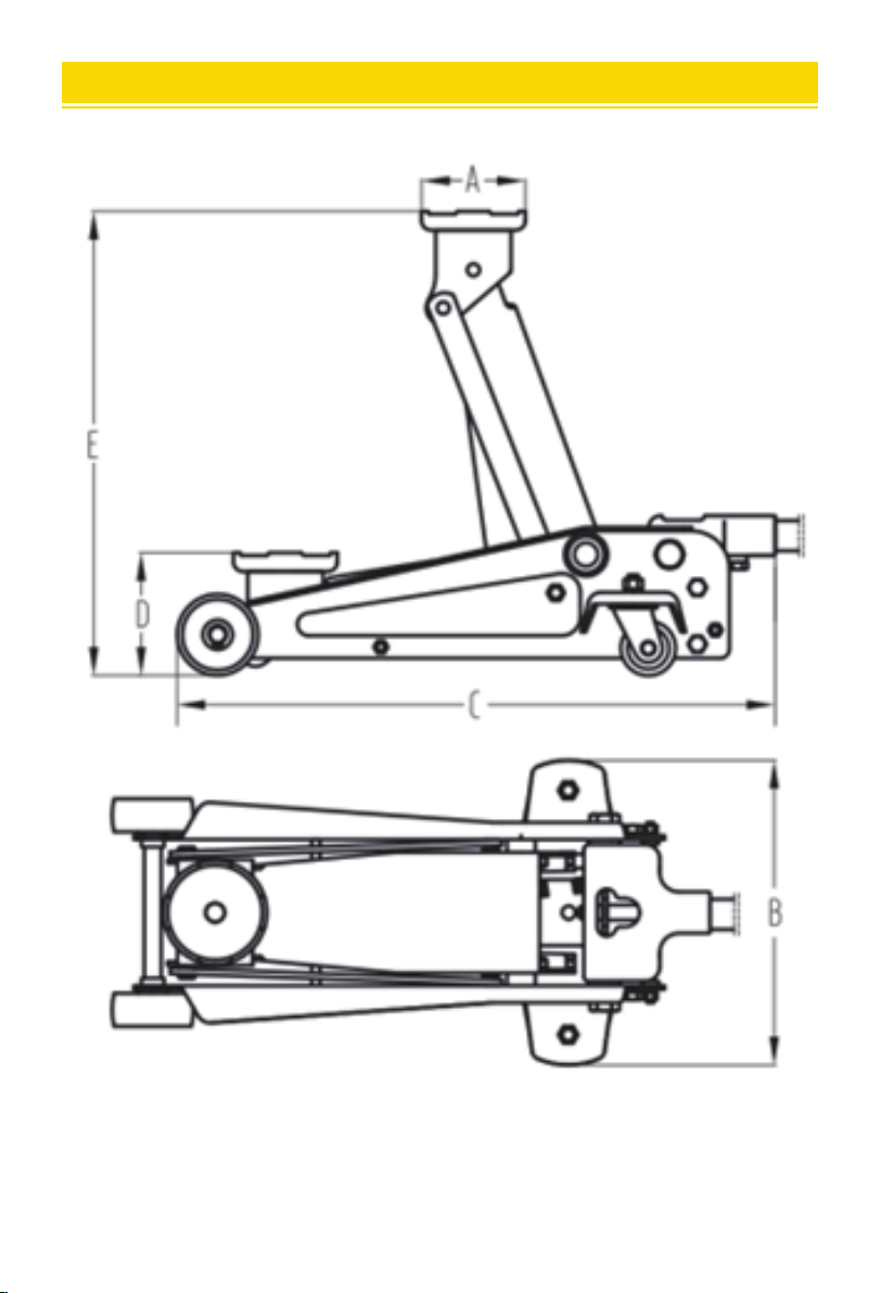
Tray Diameter A(mm) Φ99 Φ119 Φ99
Width B(mm) 250 320 325
Length C(mm) 585 710 740
Minimum Height D(mm) 80 95 90
Maximum Height E(mm) 365 475 500
Handle Length (mm) 950 1145 1145
Product Weight(kg)
G.W.: 17.8 kg
N.W.: 15.7 kg
G.W.: 30.3 kg
N.W.:
27.5 kg
G.W.: 32.9 kg
N.W.: 30.1 kg
Material Aluminum + Steel Aluminum + Steel Aluminum + Steel
Model
parameter
WD-A-02250-A00-0
Hydraulic Single Cylinder
205
550
85
380
800
G.W.: 15 kg
N.W.:13.2 kg
2.5 Tons
Φ62
Steel