Please review this important assembly, safety and warranty information about your
new Merrithew Health & Fitness Reformer and keep it handy for future reference.
OWNER’S MANUAL
Reformer
Reformer Owner’s Manual
2
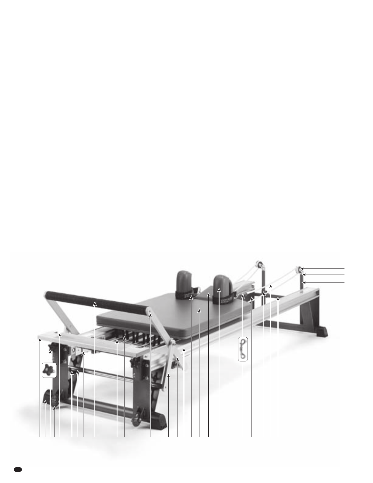
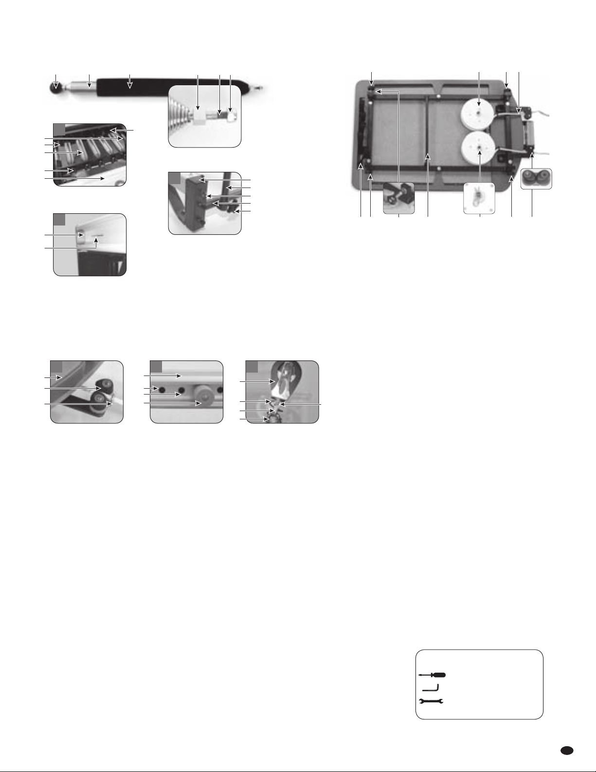
1 Wooden Standing Platform
2 Plastic Foot
3 1⁄2" Star Knob
4 Easy-Roll Wheel
5 Accessory Board Receptacle
6 Footbar Adjustment Cradle
7 Swing Arm Support
8 Gearbar Slot [fig. B]
9 Gearbar [fig. B]
10 Footbar
11 Spring [fig. A & B]
12 Spring Ball
13 Spring Coil [fig. A]
14 Fixed Cube Nut [fig. A]
15 Spring Bolt [fig. A]
16 Nylon Locknut [fig. A]
17 Plastic Spring Holder [fig. B & E]
18 Floating Roller [fig. E]
19 Fixed Roller [fig. E]
22 3⁄8" Star Knob [fig. D]
23 Rope Housing Reel [fig. E]
24 Cotter Pin [fig. E]
25 Self-Locking Cleat [fig. E & G]
26 Rope Retaining Hook [fig. G]
27 Socket Head Cap Screw
28 C-channel [fig. C]
29 Carriage Stopper Position [fig. H]
30 Carriage Stopper [fig. C & H]
31 Small Swing Arm Bar
32 Large Swing Arm Bar
33 Aluminum Rail [fig. H]
34 Soft Reformer Loop
35 Carriage [fig. E]
36 Headrest
37 Padded Shoulder Rest
38 Double-Ended Swivel Spring Clip
39 Serial Number [fig. C]
40 Pulleybar Receptacle
41 Rope [fig. E]
42 Horizontal Metal Bar pro & rehab
43 Horizontal Metal Frame [fig. D]
44 Pulley [fig. H]
45 Pulley Spring [fig. H]
46 Eyehook [fig. D & H]
47 Pulleybar [fig. D]
48 Receptacle Cap
Part Identification for the STOTT PILATES Reformers
NOTE: Parts may not be exactly as shown.
Photo shown is a Professional Reformer.
Part IDs are the same for other Reformer
models (SPX Max, Rehab and V2 Max Plus).
Please see page 6 for all Reformers included.
44
45
47
BACK OF
REFORMER
1 2 3 4 5 6 7 10811 17 27 31 32 3433 35 36 37 38 40 41 42
FRONT OF
REFORMER
39
merrithew.com 3
D
REQUIRED TOOLS:
one flat-head screwdriver
one 1/4” (6mm) hex key (supplied)
one open-end wrench (supplied):
1/2” (13mm) x 7/16” (11mm)
17 2119
18 23
24 2519
18 41
FIG E – RETRACTABLE ROPE SYSTEM CARRIAGE [35]
20
47
48
22
43
46
VERTICAL FRAME
RECEPTACLE & STAR KNOB
BOLT END OF SPRING
FIG A – SPRING
B
GEARBAR & SPRINGS
13 ?
BALL END OF SPRING
C
SERIAL NUMBER STICKER
39.
28.
G H
45.
F
25.
26.
44.
46.
35.
29.
30.
28.
33.
58.
PULLEY BLOCKCARRIAGE STOPPING SYSTEMCLEAT SYSTEM
57
14 15 16
1212
11
12
17
9.
8.
?
Reformer Owner’s Manual
4
Reformer Owner’s Manual
4
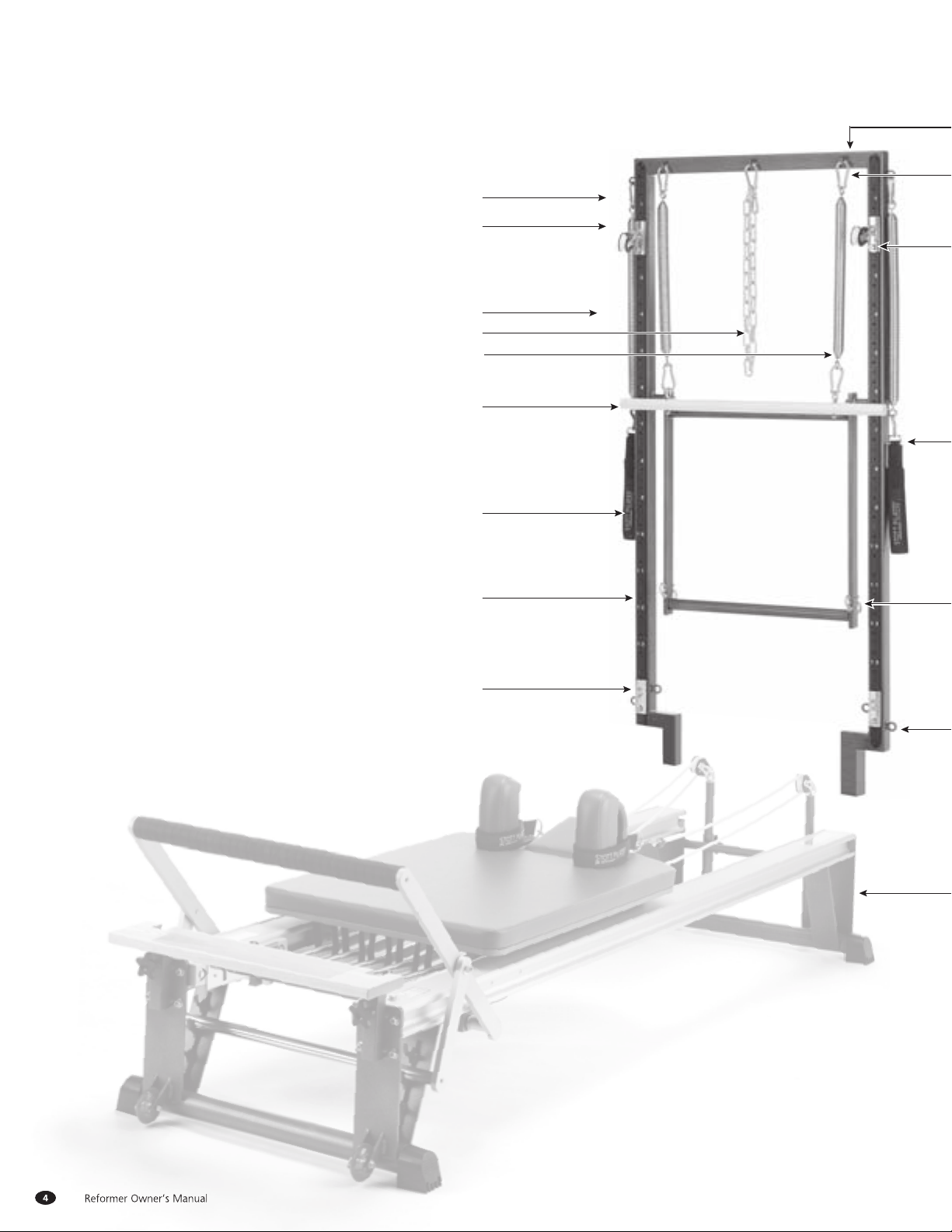
50 Vertical Frame [fig. I]
51 Spring Clip
52 Vertical Sliding Track plus-style
53 Traveling Pulley plus-style
54 Traveling Pulley Eyehook plus-style
55 Pulley Spring plus-style
56 Pulley plus-style
57 Threaded Bolt plus-style
58 Swivel Harness plus-style
59 Spring-Loaded Stopper plus-style
60 Stopper Position plus-style
61 Leg Spring, white
62 Safety Chain
63 Roll-Down Spring, black
64 Roll-Down Bar
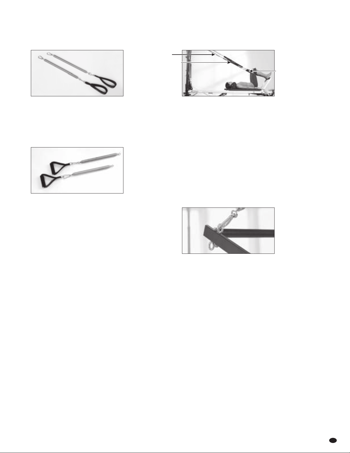
65 Padded Long Spine Strap
66 Push-Thru Bar
67 Traveling Spring Hook
68 Fixed Eyehook [fig. I] plus-style
69 Light Arm Spring, yellow [fig. J]
70 Foam-Grip Handle [fig. J]
71 Hex Bolt
72 Vertical Frame Receptacle
73 Push-Thru Spring, blue [fig. K]
74 Extension Strap [fig. L]
75 Locking Spring Clip [fig. K]
Part Identification for the Vertical Frame
NOTE: Parts may not be exactly
as shown. Photo shown is a
Professional Reformer. Part IDs are
the same for other Reformer models
(SPX Max, Rehab and V2 Max Plus).
PLUS-STYLE VERTICAL FRAME
52.
61.
63.
62.
64.
67.
65.
66.
53.
merrithew.com 5
50.
54
55
58
57
59
71
72
60
51
68
PUSH-THRU SPRING WITH
LOCKING SPRING CLIP
74.
68.
69
50
50
66
56
51
FIG I – TRADITIONAL VERTICAL FRAME
VERTICAL FRAME RECEPTACLE
SPRING CLIP ON PUSH-THRU BAR
EXTENSION STRAPS
LIGHT ARM SPRING WITH
FOAM-GRIP HANDLE
68
TRAVELING PULLEY ON
MAX PLUS FRAME
52
J
K
L
REQUIRED TOOLS:
one open-end wrench
70
73
75
Reformer Owner’s Manual
6
STOTT PILATES Reformers are favored among Pilates professionals for their superior adaptability, versatility, craftsmanship and
smooth carriage ride. Allof our units feature easy adjustments to accommodate different sizes and abilities. The unique spring
resistance of this machine helps generate smooth muscular contractions that develop strength without bulk.
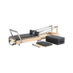
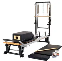
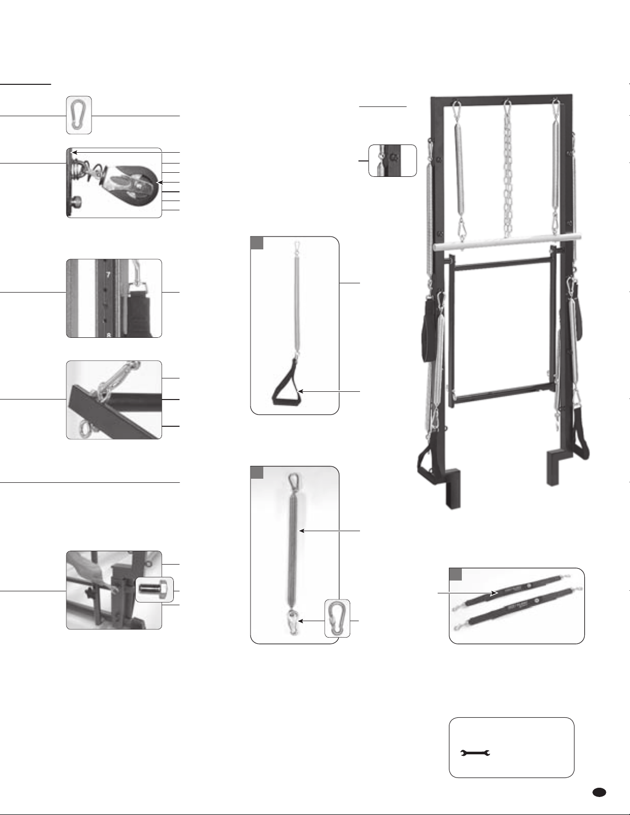
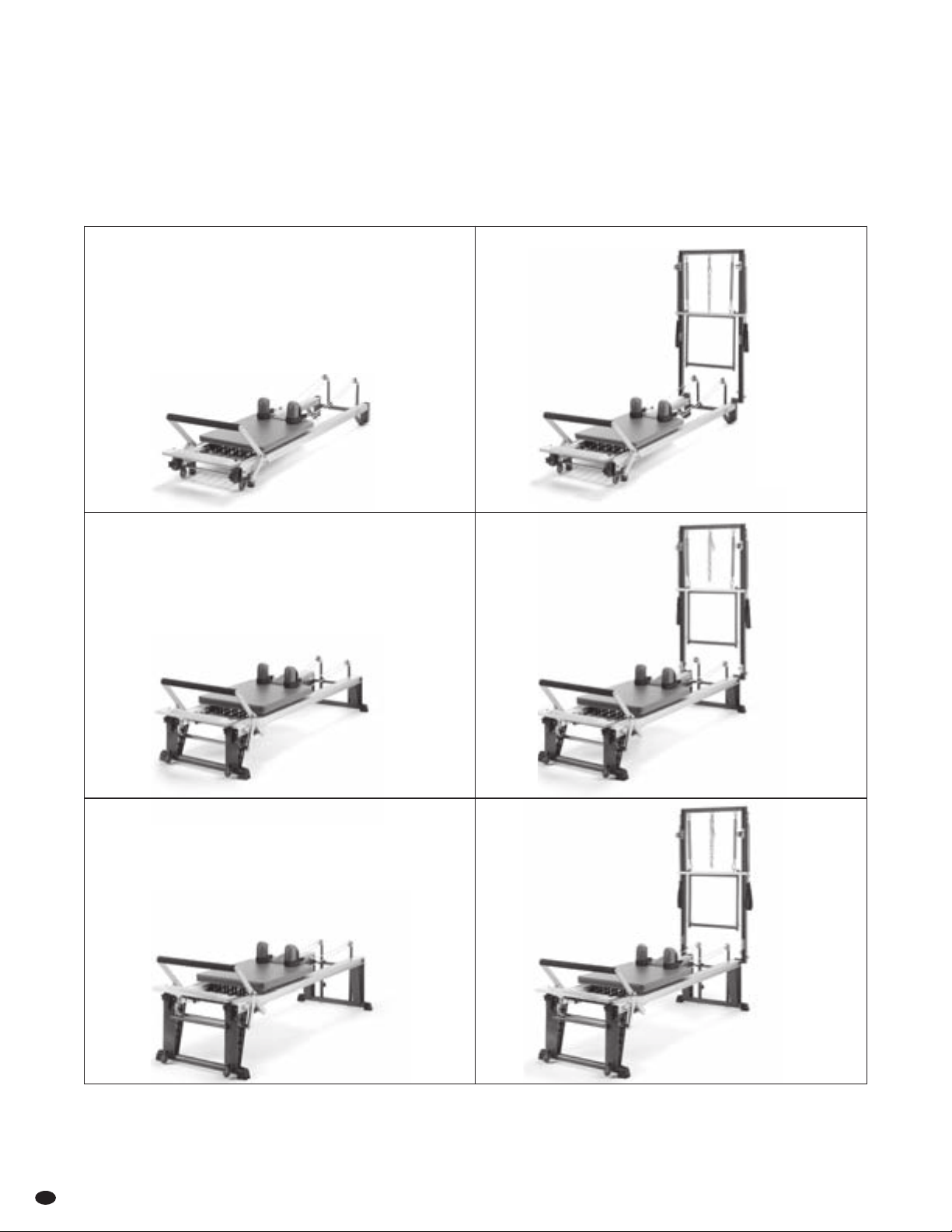
The STOTT PILATES Family of Reformers
V2 Max Plus™
Reformer*
V2 Max
Reformer™
V2 Max Plus™
Rehab Reformer*
SPX Max Plus™
Reformer*
includes
Retractable Rope System
and Vertical Frame with
Traveling Pulley System
includes
Retractable Rope System
and Vertical Frame with
Traveling Pulley System
includes
Retractable Rope System
and Vertical Frame with
Traveling Pulley System
V2 Max Rehab
Reformer™
SPX Max™
Reformer*
includes
Retractable Rope System
includes
Retractable Rope System
includes
Retractable Rope System

merrithew.com 7
User Guidelines
The STOTT PILATES Reformer is a sophisticated piece of equipment
that, when used properly, can facilitate many Pilates exercises
safely and effectively. However, care and caution must be taken
as there are some inherent dangers when using any exercise
equipment – especially when spring resistance is involved.
For inexperienced or first-time users, Reformers should only
be used under the supervision of a trained professional.
This manual includes general guidelines for setup and usage.
To get the most out of your Reformer, Merrithew Health & Fitness
offers instructional DVDs and manuals. Personalized training is
offered through our Licensed and Corporate Training Centers.
Visit merrithew.com for more information.
For questions or technical assistance,
email [email protected]
Care & Cleaning
Wipe vinyl surfaces with a mixture of water and tea tree oil, a
natural disinfectant. Add 1tsp of tea tree oil to a 1L or 1qt spray
bottle of water. A mixture of mild soap and water may be used to
remove more persistent dirt. Ensure cleaner does not leave an oily
residue, or make surfaces slippery.
Clean channels, rails and rollers weekly with a damp cloth.
Avoid spraying liquid directly onto surfaces.
CAUTION: Never use oil lubricants as they may damage rollers.
IMPORTANT!
This manual contains important assembly, safety and warranty
information. Read the manual carefully before using your new
Reformer and keep the manual on hand for future reference.
UNSAFE OR IMPROPER USE OF THIS EQUIPMENT BY FAILING TO
READ AND COMPLYWITH ALL REQUIREMENTS ANDWARNINGS
COULD RESULT IN SERIOUSINJURY.
It is impossible to predict every situation and condition that can
occur while using your Reformer. Merrithew Health & Fitness™
makes no representation about the safe use of the Reformer
any exercise equipment that cannot be predicted or avoided,
and you assume the responsibility for that risk.
Please ensure that you and your clients/patients have received
proper instruction regarding the correct and safe use of Merrithew
Health & Fitness equipment. We recommend cautious assembly and
usage and wish you many hours of safe and effective exercise.
Safety Instructions
WARNING: As with any athletic activity, the use of exercise
equipment involves risk of injury, damage and/or death.
By choosing to use Merrithew Health & Fitness equipment,
you and/or your clients/patients assume responsibility for
that risk, not the people who sold you the equipment,
distribute and/or manufacture it.
w Replace springs every 24 months, or as needed within that
period if deformation occurs.
w Check wear on single, locking and double-ended spring clips
and replace every 12 months.
w Ensure footbar is securely fastened.
w Ensure swing arm support is securely fastened.
w Ensure carriage stopper is fully inserted in one of the six
positions at all times.
w Ensure all nylon locknuts and spring bolts are securely fastened.
w Check wear on all star knob threads, replace as needed.
w Check wear on ropes, straps and spring clips, replace as needed
with 12 month period.
w Ensure shoulder rests are inserted completely.
w Check that nylon locknuts, spring bolts and spring balls
are securely fastened.
w Inspect the retractable rope system to confirm the ropes are in
position and the threaded bolts of the cleats and pulley blocks
are secure (if applicable).
w Check that all hex bolts on the Reformer’s two vertical frame
receptacles are tight and that the vertical frame is securely
anchored (if applicable).

Reformer Owner’s Manual
8
Proper maintenance and timely replacement of your
equipment or component parts is your responsibility
as it helps reduce the risk of injury. Conduct a regular
inspection of the following:
Daily
w Clean rails with a damp cloth.
w Inspect retractable rope system to confirm ropes are in position
and threaded bolts of the cleats and pulley blocks are secure.
w Ensure shoulder rests are fully seated on carriage.
w Clean all upholstery after each use, using a soft cloth and
gentle cleanser.
Weekly
w Ensure that all nuts, bolts and screws are securely fastened.
w Ensure plastic feet are securely attached and have the flat side
facing towards the floor.
w Ensure footbar and chrome adjuster bar are securely fastened.
w Ensure pulley bar star knobs are securely tightened.
w Inspect for excessive wear and replace rollers as needed.
Sit on the carriage and test rollers, listening for any thumping
or grinding – the ride should be quiet and whisper smooth.
w Inspect all springs for wear and damage and replace immediately
as needed.
w Check that bolts on the vertical frame receptacles are securely
fastened. Inspect traveling pulleys to ensure that threaded bolts
of the pulley blocks are secure. Test to confirm that the plunger
button is locking securely into the vertical frame.
Monthly
w Check rope wear and replace as necessary.
w Check that spring bolts and spring balls are securely fastened.
w Check all spring clips to ensure proper fastening.
w Check wear on star knobs and replace as necessary.
w Check strap wear and replace as necessary.
Yearly
w Replace all spring clips
Every 2 Years
w Replace all springs
REPLACE ALL SPRINGS EVERY 24 MONTHS AND SPRING CLIPS
EVERY 12 MONTHS OR AS NEEDED WITHIN THAT PERIOD.
FAILURE TO PERFORM RECOMMENDED SAFETY CHECKS, OR USING
THE MACHINE WITH IMPROPERLY ADJUSTED, BROKEN OR WORN PARTS,
COULD RESULT IN SERIOUS BODILY INJURY.
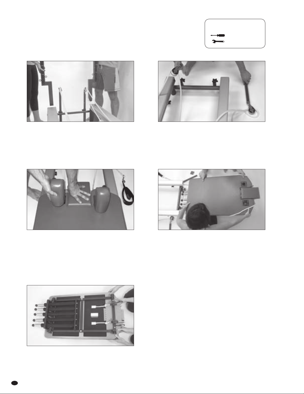
IMPORTANT! PLEASE DO NOT ATTEMPT TO ASSEMBLE ON
YOUR OWN. THIS IS, AT MINIMUM, A JOB FOR TWO PEOPLE.
PLEASE READ THESE INSTRUCTIONS COMPLETELY BEFORE
BEGINNING ASSEMBLY.
Place all parts from the box in a cleared area and position them
on the floor in front of you. Remove all packing material from
your area and place them back into the box. Do not dispose of the
packing materials until assembly is completed. To prevent unsafe
or improper use, please read each step carefully before beginning.
For assistance or any missing parts:
Call: Toll-free in North America 1-800-910-0001
Toll-free in United Kindom 0800-328-5676 or
Email [email protected]
Please refer to the assembly instructions included in this Owner’s
Manual for initial Assembly Instructions and Part Identification.
Mechanical Safety Check
merrithew.com 9
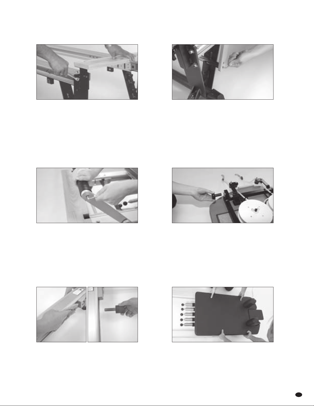
Assembly Instructions
2 Place swing arm support [7] in one of the footbar
adjustment cradles [6] and fasten tosmall swing arm
bars [31] with socket head cap screws [27].
4 On Reformer carriage, insert floating rollers [18] into
bronze bushings [20].
6 Align fixed rollers with c-channels, then adjust floating
rollers as necessary before guiding carriage into rails.
CAUTION: Westrongly advise that two people perform
this operation to prevent damaging rollers.
1 Place metal plate of wooden standing platform [1]
on threaded bolts on front of Reformer and fasten
with 5⁄16" lock nuts and washers.
CAUTION: Ifyou are using a ratchet system to tighten
nuts, be careful not to over-tighten.
NOTE: Steps 1 to 7 are complete upon delivery for all
SPX Max™ models.
3 Fasten footbar [10] to top of large swing arm bars [32]
with socket head cap screws [27].
NOTE: To help ensure proper alignment, do not tighten
completely until all components of footbar are assembled.
Apply pressure to footbar before tightening all socket
head cap screws.
5 Wipe rails [33] and inner c-channels [28], with a damp cloth
to remove dust and dirt. Insert carriage stopper [30]
in one of six positions.
CAUTION: The carriage stopper must be inserted into one
of the six positions AT ALL TIMES. Never use oil lubricants
as they may damage rollers.
Reformer Owner’s Manual
10
CONT’D
Assembly Instructions
8 Insert shoulder rests [37] into receptacles with handles
facing pulleybars and closest to outside edges of carriage.
10
To extend ropes, depress below rope retaining hooks
[26] and lift out of self-locking cleats [25]. Reel out length
of rope required.
12 Reattach double-ended swivel spring clips and soft
reformer loops [34].
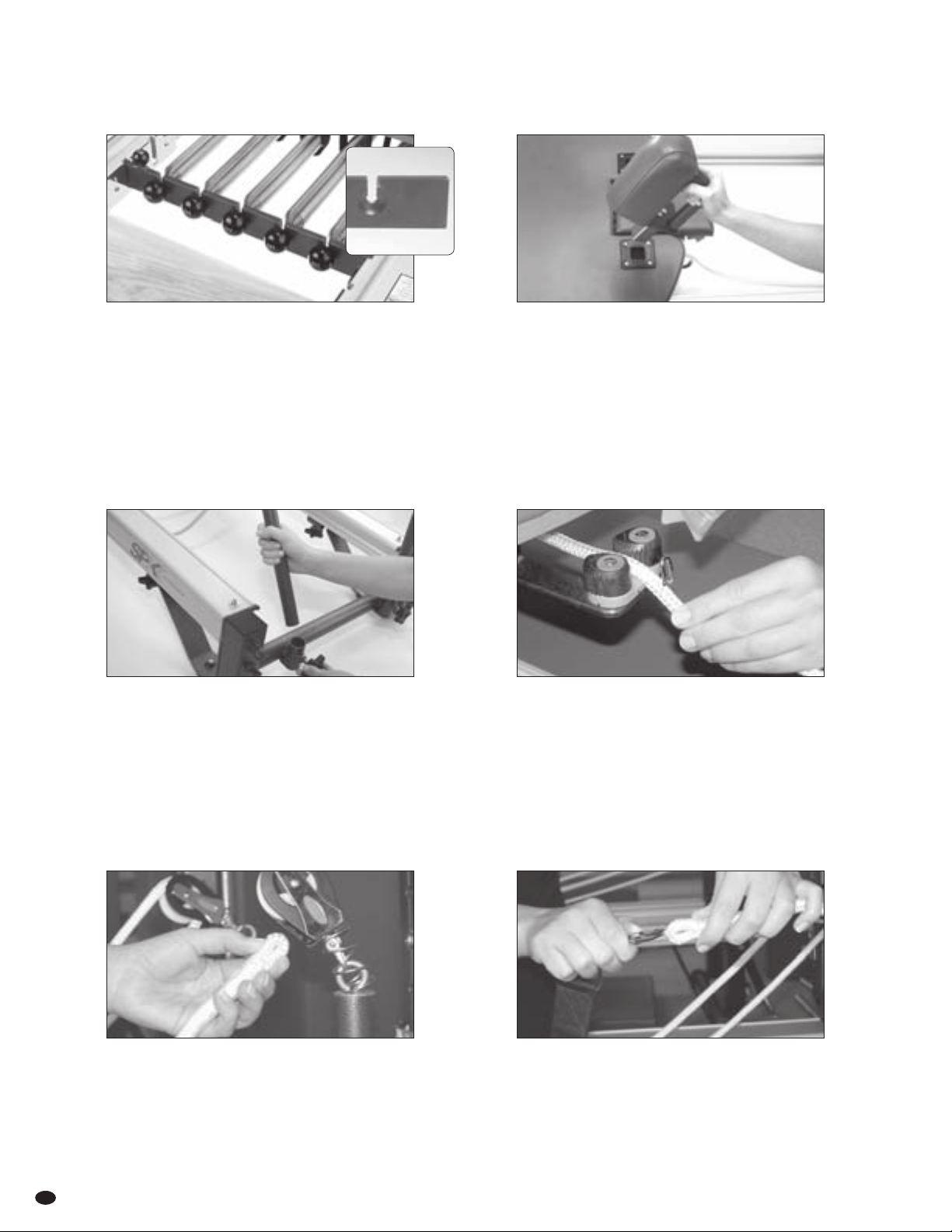
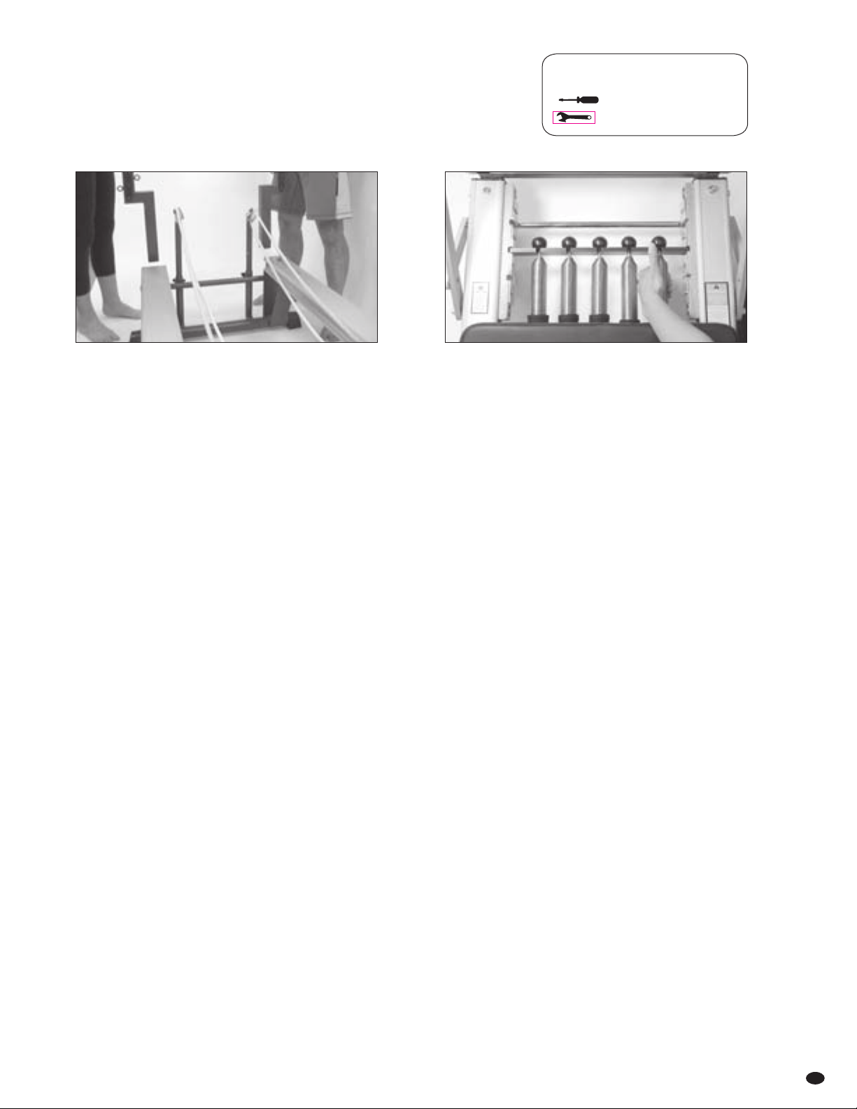
7 Insert gearbar [9] into the middle gearbar slots [8] with
the concave indentations [inset above] facing the wooden
standing platform [1].
9 Insert pulleybars [47] into receptacles [40] at back of reformer
and tighten star knobs [3]. Ensure eyehooks [46] on top of
pulleybars are parallel to rails [33].
PROFESSIONAL & REHAB MODELS: Align top of pulleys
with top of shoulder rests.
11 Remove double-ended swivel spring clips [38], pinch
end loop of ropes [41] and insert through the front of
pulleys [44].
merrithew.com
#6 #5 #4 #3 #2 #1
11
CONT’D
Assembly Instructions
14 Place soft reformer loops on carriage to line up fixed D-rings
on straps with end of metal plate of shoulder rests [37].
16 To shorten length slightly, pinch ropes [41] between
carriage [35] and self-locking cleats [25] and pull toward
carriage. Grasp ropes at retaining hooks [26] and tug
to engage cleats.
13 To determine correct length of ropes, setcarriage stopper
[30] in the second position. Attach springs to gearbar [9]
to ensure carriage [35] does not move.
15 Once rope length has been established, reset ropes in
self-locking cleats [25] then set fully into rope retaining
hooks [26].
17 Carefully lift Reformer and slide on plastic foot [2].
Ensure they sit flat on floor.
NOTE: Not necessary on SPX Max models.
Reformer Owner’s Manual
12
Assembly Instructions – Vertical Frame
19
PLUS-STYLE: To use traveling pulleys [53] extend ropes
and detach double-ended swivel spring clips [38] and
soft reformer loops [34]. Pinch end loop of ropes and
insert through the bottom of traveling pulleys. Re-attach
double-ended spring clips and soft reformer loops.
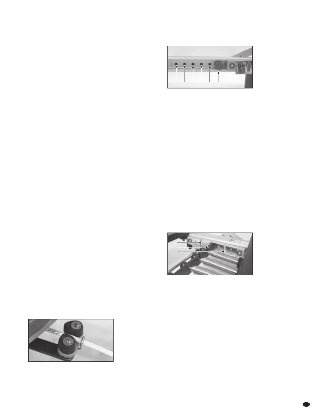
18 Remove receptacle caps [48] with a flat-head screwdriver.
Slide vertical frame into receptacles [72]. For plus-style
models, position pulley system facing carriage. For traditional
models, position highest eyehooks facing carriage. Tighten all
four hex bolts [71]. Attach springs, roll-down bar and safety
chain as illustrated on page 5 [Fig I].
20 To alter the height of traveling pulleys, pull out spring-loaded
stoppers [59]. Shift the traveling pulleys up or down vertical
sliding tracks [52] and release spring-loaded stoppers.
Shake pulleys to confirm they are fully locked into stopper
positions [60].
21 For exercises using arm [69] or leg springs [61], attach
springs to traveling spring hooks [67], and adjust height
in the same way as traveling pulleys. After changing
position, shake spring hooks to confirm they are fully
locked into stopper positions.
merrithew.com 13
Safety & Usage
GETTING ON THE REFORMER
SUPINE POSITION (LYING ON BACK)
w Sit on Reformer carriage, facing side.
w Reach hand nearest the footbar across your body and
place it onto the shoulder rest.
w Tuck opposite shoulder under arm and roll onto back,
lowering head onto headrest.
w Bring legs up and place feet on footbar, lowering arms by sides.
STANDING OR KNEELING POSITIONS
The carriage is a moving platform. Special attention must always
be paid to maintaining balance and stability, especially when
performing kneeling orstanding exercises.
w Before you begin, ensure one or more springs are engaged
in the gearbar to secure the carriage.
FOR SPX MAX™ REFORMERS:
w Never stand with both feet on woodenstanding platform.
w Place one foot on secured carriage.
w Carefully place other foot onto the wooden standing platform.
A gripper mat may be used to prevent slipping.
w Chemical-based cleansers used around Reformer feet may cause
permanent marking on floors. Our warranty does not cover
this damage. We highly recommend avoiding chemical-based
products and suggest placing a non-slip mat under the machine.
FOR ALL OTHER STOTT PILATES REFORMERS:
w Place one foot on wooden standing platform.
w Carefully place other foot onto the secured carriage.
A gripper mat may be used to prevent slipping.
ALL MODELS OF REFORMERS:
w When standing on the carriage with two feet, it is advisable
to have a spotter to steady the carriage.
KEEP HANDS & FEET SECURE
Whenever placing hands or feet on the footbar, shoulder rests
or headrest, ensure they will not slip during exercise. Gripper mats
may be used.
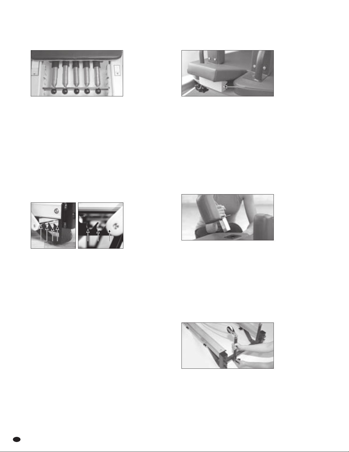
SITTING OR LYING ON A BOX
Always place reformer box in a stable position onthe Reformer
and sit directly in the middle to avoidtipping. When using
footstrap, ensure it isunderneath the wooden standing
platform and securely clippedtogether.
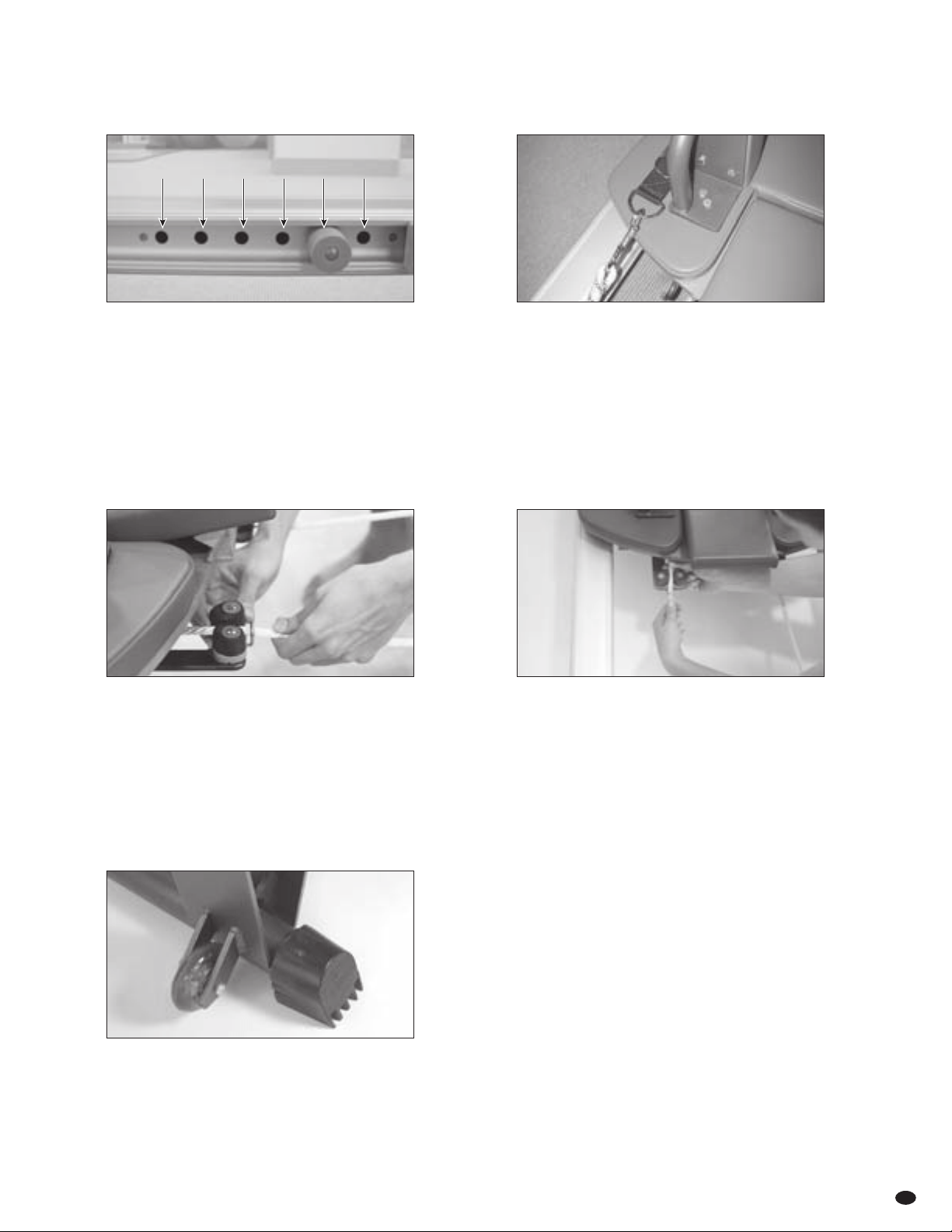
CARRIAGE STOPPER
The carriage stopper position determines how close the carriage
slides in toward the wooden standing platform and dictates the
body’s range of motion.
The hole closest to the wooden standing platform is referred
to as position #1; the next is position #2, etc.
Adjusting the Carriage Stopper
w Do not sit on carriage while adjusting.
w Remove all springs from gearbar.
w Insert carriage stopper in one of six positions.
w Ensure carriage stopper is completely inserted.
The carriage stopper position should be chosen to give the
optimal range of motion based on the exercise and the individual
performing it. It will also affect the initial tension on the springs
in relation to the gearbar.
NOTE: The carriage stopper must be inserted in one of the six
positions AT ALL TIMES. USING THE REFORMER WITHOUT THE
CARRIAGE STOPPER MAY CAUSE DAMAGE TO THE GEARBAR
BLOCK AND ROLLERS.
#6 #5 #4 #3 #2 #1
RETRACTABLE ROPE SYSTEM
Prior to use, confirm that the retractable rope system is in good
order and rope is secured through self-locking cleats and rope
retaining hook. (See Assembly Instructions on page 10 and 11.)
GEARBAR
The gearbar position determines the amount of initial tension
on the springs. The slot closest to the wooden standing platform
is referred to as position #1, the next is position #2, the last is
position #3.
Adjusting the Gearbar
w Do not sit on carriage while adjusting.
w Remove all springs while holding gearbar in place.
w Place gearbar in desired position.
w Ensure gearbar slides fully into slots.
w Face concave indentations toward Footbar.
Position gearbar relative to the carriage stopper to create initial
tension on the springs, i.e. the gearbar should not be in position
#3 if the carriage stopper is in position #1 or #2 as there will not
be any initial spring tension.
#1
#2
#3
Reformer Owner’s Manual
FOOTBAR
The footbar can be set at four different heights to facilitate various
reformer exercises and to accommodate physical differences and
abilities. The cradle closest to the gearbar is position #1, the cradle
farthest away is position #4.
Adjusting the footbar
w The footbar can be adjusted while standing beside the reformer
or sitting on the carriage.
w Gently pull footbar up and lift swing arm support out of footbar
adjustment cradle.
w Lift or lower footbar to the desired height and place swing arm
support securely into nearest cradle.
SPX Max & SPX Max Rehab
#4 #3 #2 #1 #4 #3 #2
SPX Max
14
Safety & Usage CONT’D
SPRINGS
The number of springs attached to the gearbar determines the
total amount of resistance. Reformers are equipped with either
one 50% and four 100%-tension springs OR one 25%, one 50%,
and three 100%-tension springs. (See page 20 for more details.)
Adjusting springs
w Take care when attaching and detaching springs.
w For safety, place one hand on gearbar.
w Firmly grasp spring, (not spring ball), and stretch
it to hook to or unhook from gearbar.
w Ensure ball rests securely in concave
HEADREST
The headrest adjusts to three positions: flat, half-raised or fully
raised. It should be adjusted on an individual basis to ensure neck
and shoulders are comfortable and tension-free when lying supine.
In exercises where the hips are lifted higher than the shoulders,
the headrest should be flat – even when beginning from a supine
position. In some exercises it is raised to provide a brace for
the feet.
Adjusting the headrest
w With no weight on headrest, lift it and hinge adjustment block
to rest securely onto wooden edge of carriage.
SHOULDER RESTS
Shoulder rests are removable to allow storage of the reformer
and to facilitate the use of a mat converter.
Attaching the shoulder rests
w Slide square posts into receptacles in the carriage.
Padded sides face footbar and handles are positioned
closest to edges of carriage.
w To remove, pull directly up on handles.
PULLEYBARS
SPX MAX REFORMER ONLY: Pulleybars detach for storage
without disengaging ropes. To remove, loosen star knobs and
remove pulleybars from receptacles.
When replacing pulleybars, ensure they are firmly within the
receptacles. Ensure eyehooks on top of pulleybars are parallel
to aluminum rails. Tighten star knobs securely.
Adjustment Block
merrithew.com 15
STORING SHOULDER REST
SPX MAX REFORMERS ONLY: When stacking, shoulder rests slide
conveniently into brackets affixed to the underside of the rail.
STORING PULLEYBARS
SPX MAX REFORMERS ONLY: When stacking, pulleybars can be
removed without disengaging ropes and stored in receptacles
under reformer.
MOVING REFORMERS
The front end of all reformers feature easy-roll wheels
which make repositioning simple.
NOTE SPX Max Reformers also include easy-roll wheels
on the back.
Preparing to reposition
w Ensure ropes do not drag and springs are attached to gearbar
so carriage is secure.
w Stand at the back of reformer, grasp the horizontal metal bar
or frame and gently lift. Lift reformer high enough toengage
easy-roll wheels.
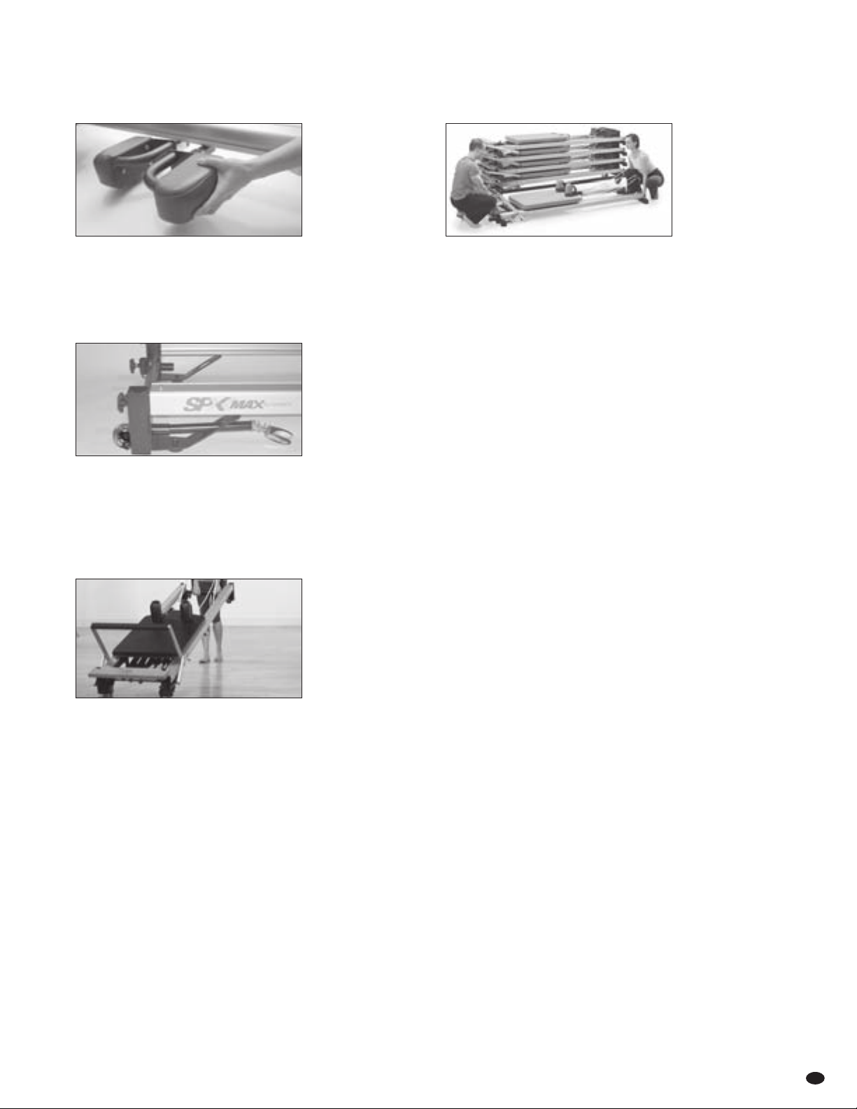
STACKING REFORMERS
STOTT PILATES offers a stackable reformer model. Up to five
SPX Max™ Reformers can be stacked on the optional rolling base
or a maximum of six on a level floor without the rolling base.
CAUTION: Do not stack Reformers higher than your height
comfortably allows lifting them.
Stacking SPX Max Reformers
w Lower footbar, insert carriage stopper into third position
and engage two springs to secure carriage.
w Remove shoulder rests and insert onto brackets under the rail.
Remove pulleybars without disengaging ropes and insert into
receptacles under the frame.
w Stacking requires two people. The stronger person should
take the front (footbar) end.
w Hold the steel plate beneath wooden standing platform.
w Hold the back end by gripping horizontal metal frame.
Safety & Usage CONT’D
Reformer Owner’s Manual
16
Safety & Usage CONT’D
PUSH-THRU BAR
SAFETY CHAIN
The safety chain must be attached when using the push-thru bar
with springs from below. Attach safety chain first, from middle
eyehook of vertical frame to either upper eyehook of push-thru
bar. Ensure spring clips are completely closed and secure.
SPRINGS FROM BELOW
When using the push-thru bar with springs from below, attach
springs to eyehooks on lowest eyehooks on vertical frame using
locking spring clips. Then attach one or two springs to eyehooks
on lower side of bar, ensuring spring clips are completely closed
and secure.
A trained professional must keep a hand on the bar at all times
and safety chain must be used.
ADJUSTABLE PULLEY SYSTEM
PLUS-STYLE ONLY: The spring-loaded track system provides
adjustability for pulleys and spring hooks throughout the range
ofthe vertical frame.
ALTERING HEIGHT OF TRAVELING PULLEYS
AND TRAVELING SPRING HOOKS
w Pull out the spring-loaded stopper on traveling pulley.
w Shift traveling pulley up or down the track and release
the spring-loaded stopper. The pulley will spring-lock into
the nearest stopper position.
w Shake traveling pulley to confirm it is fully locked into
stopper position.
w The same method applies to adjusting traveling spring hooks.
w Adjust rope length as necessary.
CAUTION: Prior to use, confirm that the traveling pulley system
is in good order and that the traveling pulley’s threaded bolts
are securely fastened.
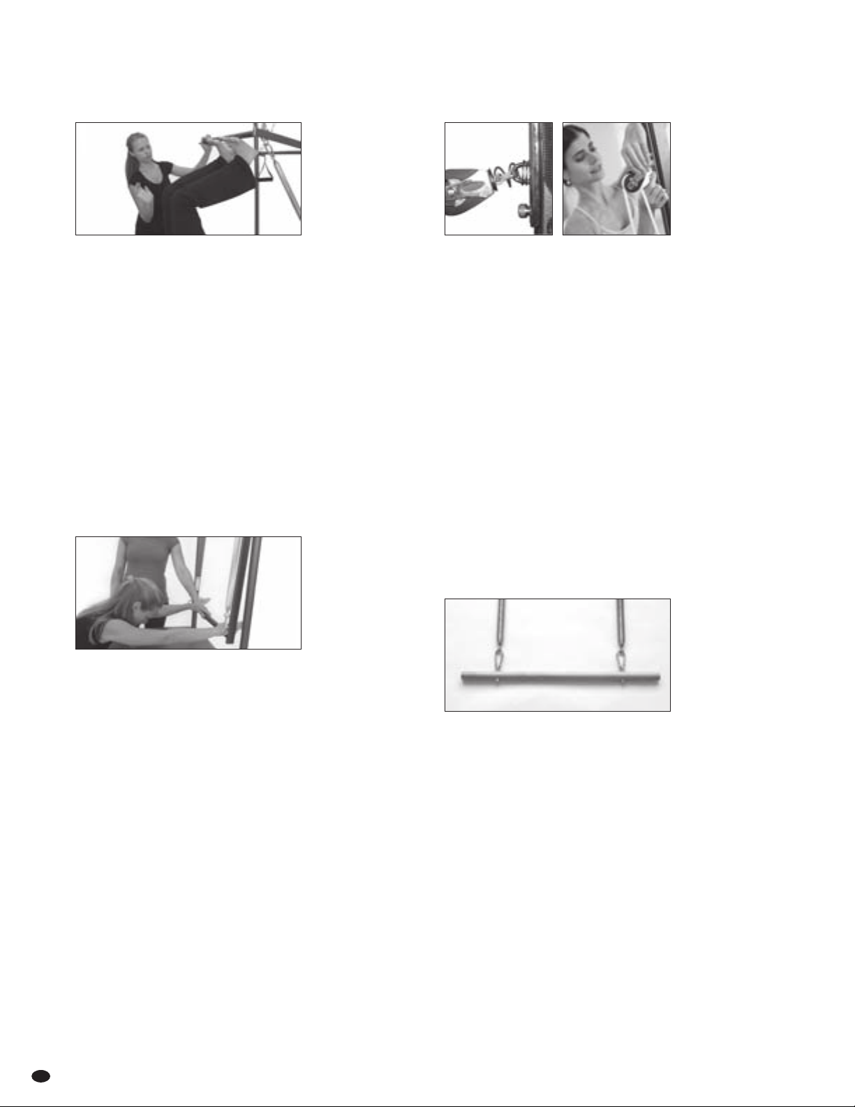
ROLL-DOWN BAR
Attach roll-down springs to roll-down bar, then to the fixed
eyehooks at the top of the vertical frame (see page 5). Both
springs must be attached. To decrease or increase, spring
tension, sub stitute light arm springs or leg springs respectively.
CAUTION: Roll-down bar can release at high velocity due to
spring tension. Ensure a secure grip at ALL times. Gripper mats
may be used.
SPRINGS FROM ABOVE
A trained professional must keep a hand on the push-thru
bar for any exercises with the springs attached from above.
CAUTION: To prevent accidental injury, never put yourface
(or another body part) above the push-thru or roll-down bar
while spotting an exercise.
Locking spring clips must be used to attach push-thru springs
from below to the vertical frame.
merrithew.com 17
Safety & Usage CONT’D
LEG SPRINGS
Attach leg springs to traveling spring hooks or fixed eyehooks
at desired height. Ensure spring clips are completely closed and
secure. Shown with padded long spine straps attached.
LIGHT ARM SPRINGS
Attach light arm springs to traveling spring hooks or fixed
eyehooks at desired height. Ensure spring clips are completely
closed and secure. Shown with foam-grip handles attached.
SPRING CLIPS
Whenever springs are used, ensure the spring clips at both
ends are closed completely. If a spring clip is only half closed
and catches on the eyehook, it may come undone and detach
with high force.
CAUTION: Locking spring clips must be used to attach push-thru
springs from below to the vertical frame. DO NOT use non-locking
spring clips.
EXTENSION STRAPS
The extension straps are valuable in supporting the knees
or legs in various exercises.
Attaching extension straps
w Move traveling spring hook to desired height along vertical
frame and release spring-loaded stopper or select desired
fixed eyehook.
w Attach leg springs, then attach extension straps to springs
and attach padded long spine straps or reformer loops to straps.
Ensure all spring clips are completely closed and secure.
w Ensure spring tension on Reformer is sufficient to return
carriage completely.
Padded Long Spine Straps
Leg Springs
Extension Straps
Reformer Owner’s Manual
18
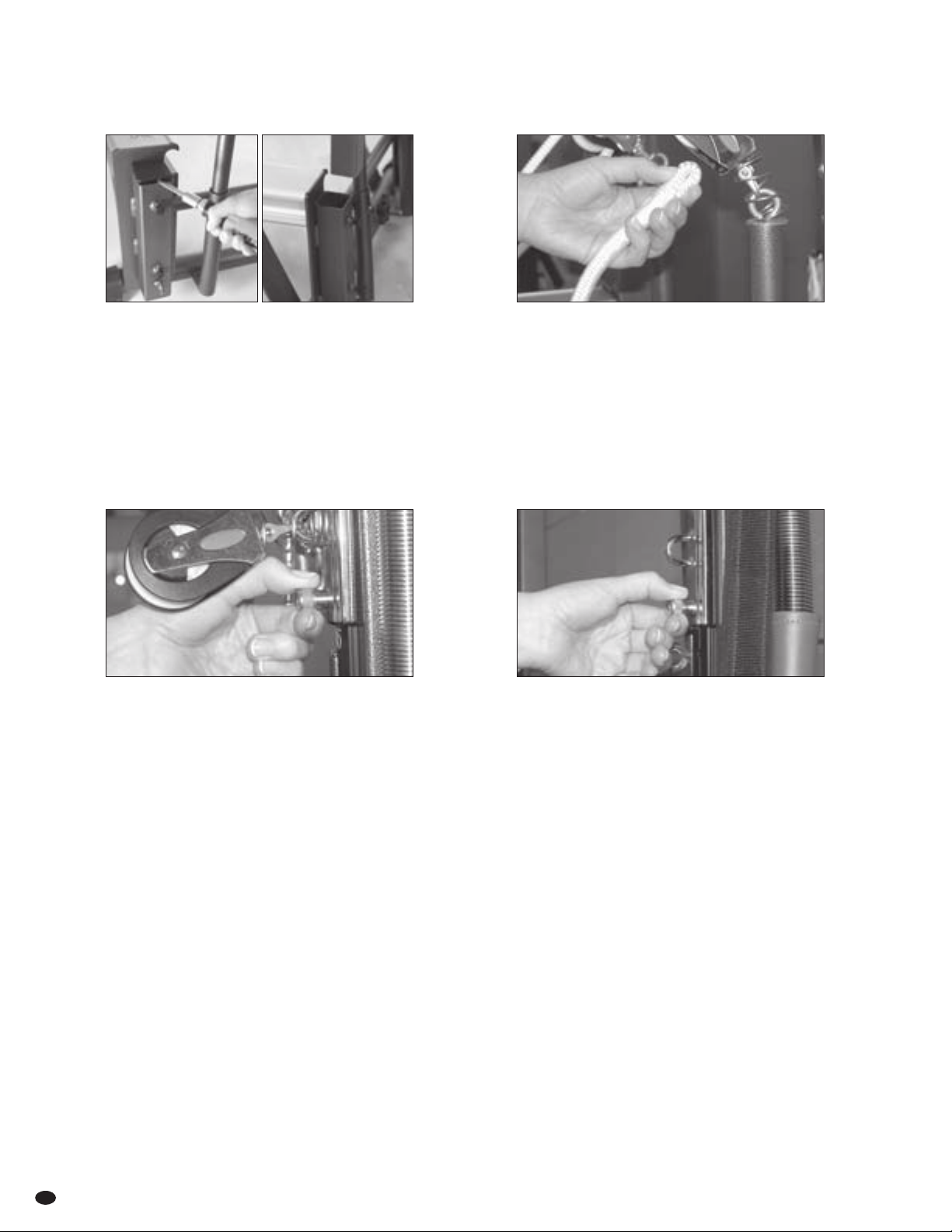
Removing Carriage
Required for replacement of Reformer springs, carriage rollers and ropes.
1 VERTICAL FRAME: Remove all springs from vertical frame,
including roll-down bar and safety chain. Loosen all four
hex bolts at the base of receptacles. Secure push-thru bar
in place by hand while removing vertical frame.
NOTE: Requires two people.
3 Remove shoulder rests (if applicable). 4 Detach all springs from gearbar. Carefully slide carriage out
of aluminum rails keeping carriage level until completely free
of rails. Turn carriage over, ensuring rollers are secure and
do not come in contact with the floor.
NOTE: Requires two people.
2 To remove carriage, remove pulleybars and place them
on floor, on either side of aluminum rails.
5 Place carriage face down on floor.
REQUIRED TOOLS:
(spx max only)
1/2"(13mm) x 9/16"(14mm)
merrithew.com 19
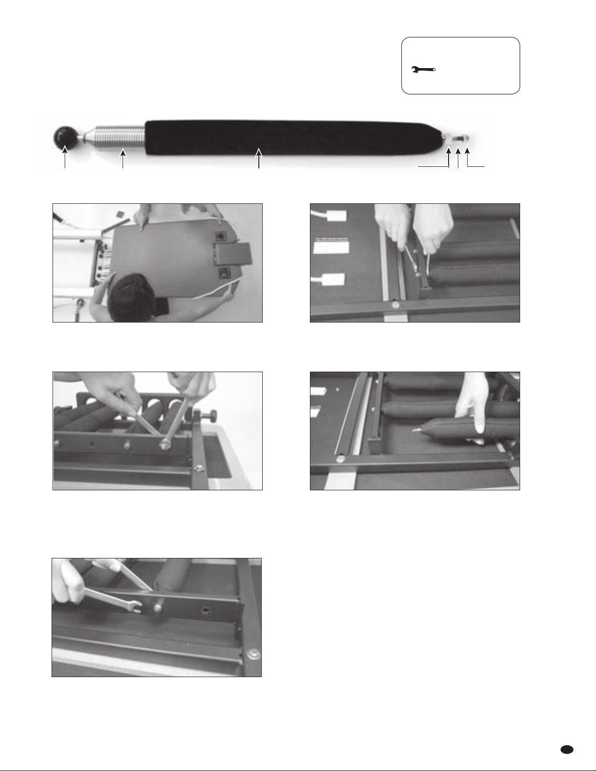
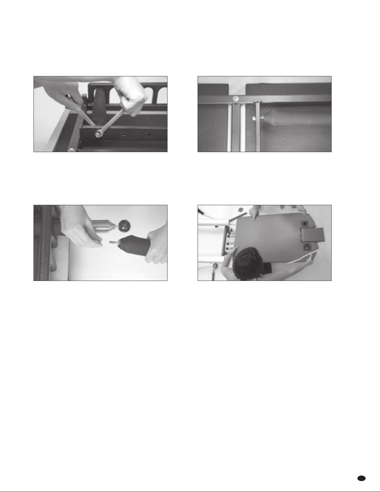
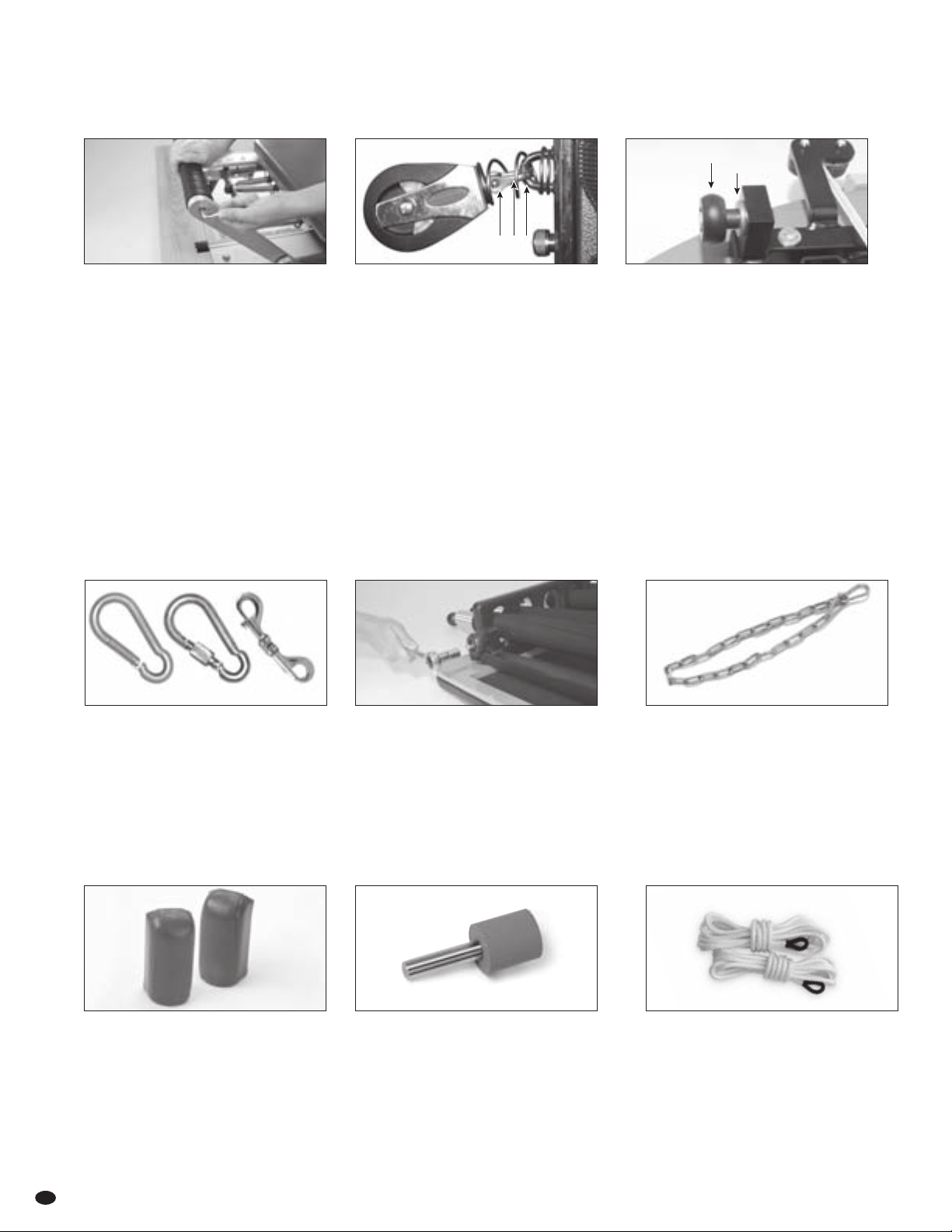
Replacing Springs
3 Using second 7⁄16" wrench on opposite side, loosen nylon
locknut. This may require a bit of force.
NOTE: Discard used nylon locknuts. New ones are
provided with new springs.
5 Repeat steps 2 to 4 on remaining springs.
4 Remove spring bolt from spring anchoring bar, then
pull ball end of the spring out of spring holding loop.
2 With 7⁄16" wrench or pliers, hold fixed cube nut in place.1 Remove carriage, see page 18 for full instructions.
REQUIRED TOOLS:
pliers or two wrench
1/2"(13mm) x 7/16"(14mm)
Spring Ball Spring SleevesSpring Coils Fixed Cube Nut
Bolt End
of Spring
Spring Bolt
Nylon Locknut
Ball End of Spring
IMPORTANT: Werecommend thatyou replace thesprings
on your reformer every two years to ensure maximum
performance and safety of your reformer at all times.
Reformer Owner’s Manual
20
Replacing Springs CONT’D
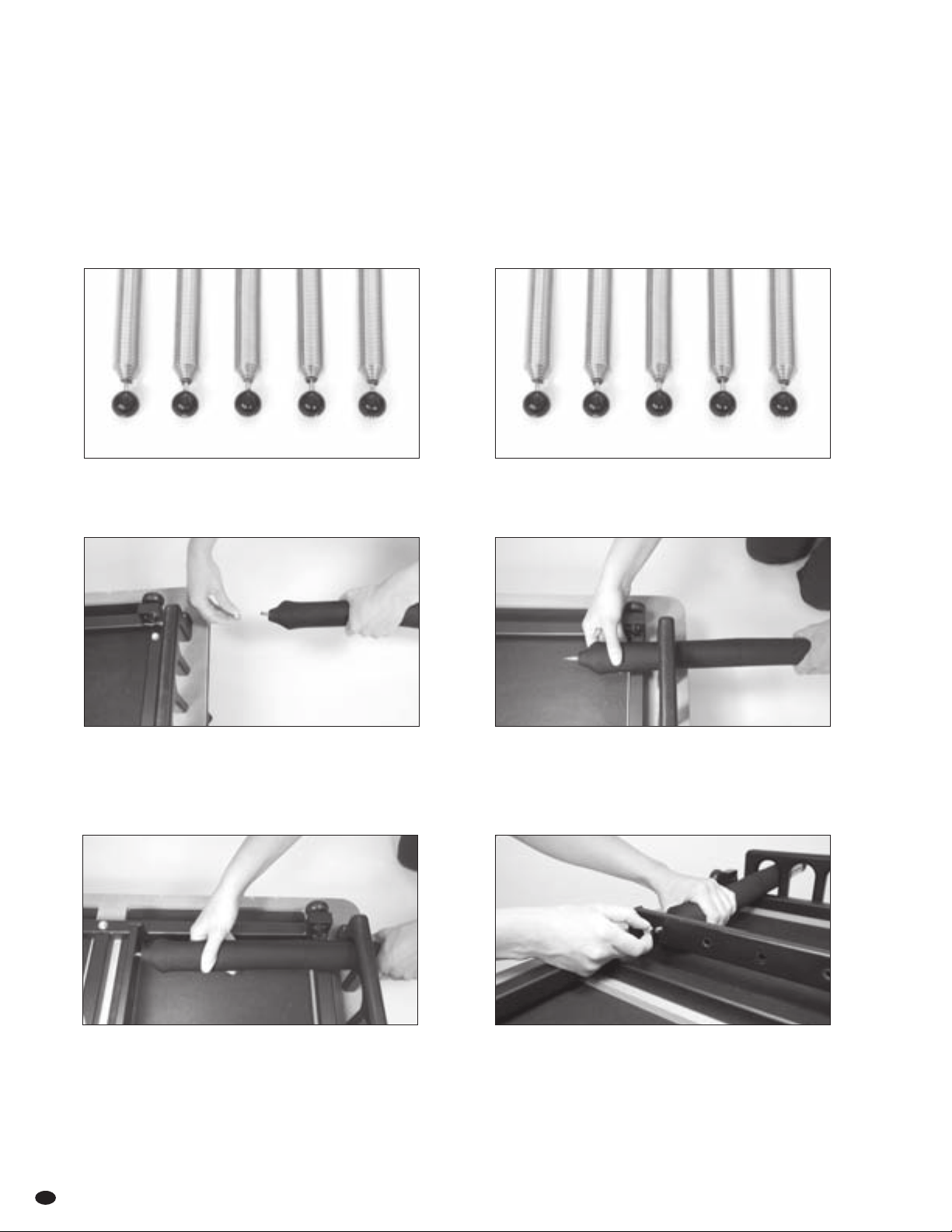
1 Remove nylon locknut from spring bolt.
3 Insert spring bolt through the corresponding
hole on spring anchoring bar.
2 Thread the spring bolt through the spring holding loop.
Place 50% spring in the center, and 25% spring to one side.
Place 100% springs in remaining positions.
HIGH-PRECISION SPRING PACKAGE
3 x 100%, 1 x 50%, 1 x 25% arrange as follows:
Place 50% spring in the center and two 100% springs
on either side.
TRADITIONAL SPRING PACKAGE
4 x 100%, 1 x 50% arrange as follows:
4 Thread nylon locknut onto spring bolt.
INSTALLING NEW SPRINGS
Determine Replacement Spring Package.
Springs are color-coded at the ball end. Red = 100%, Blue = 50%, White = 25%
100 10050100 100
#1 #2 #3 #4 #5
100 2550100 100
#1 #2 #3 #4 #5
merrithew.com 21
Replacing Springs CONT’D
INSTALLING NEW SPRINGS CONT’D
7 Repeat steps 1 to 6 for remaining springs. 8 Replace carriage, see page 24 for full instructions.
6 Both nylon locknut and fixed cube nut should
be snug up against spring anchoring bar.
5 Hold fixed cube nut in place with 7⁄16" wrench.
Using second 7⁄16" wrench, tighten nylon locknut.
NOTE: Do not reuse old nylon locknuts.
Reformer Owner’s Manual
22
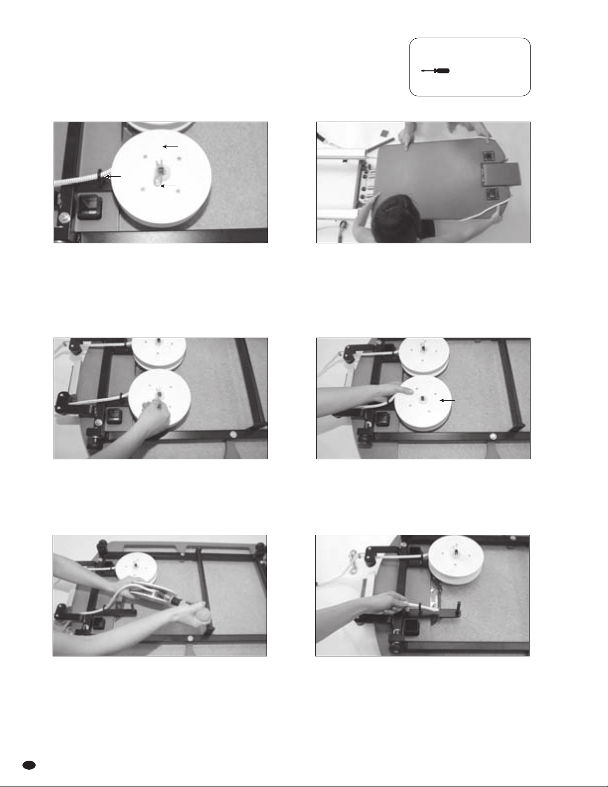
Replacing Retractable Ropes
NOTE: Please read full instructions before beginning rope replacement.
1 Expose underside of carriage to locate rope housing reels
and cotter pin.
NOTE: This step can be done by either removing carriage
or turning Reformer onto its side with springs engaged.
3 Pull out cotter pin and remove plastic washer
from rope housing reel.
5 Undo screw and separate from rope. Retain screw and
cup washer. Remove old rope and discard.
2 Remove carriage if necessary, see page 18
for full instructions.
4 Remove rope housing reel from square shaft
and uncoil rope.
6 Feed straight end of new rope through eyehook projecting
from reel bracket (refer to image in step 1). This is the end
of the rope to use in step 7.
REQUIRED TOOLS:
one flat-head screwdriver
Square Shaft
Cotter Pin
Eyehook
Rope Housing Reel
merrithew.com 23
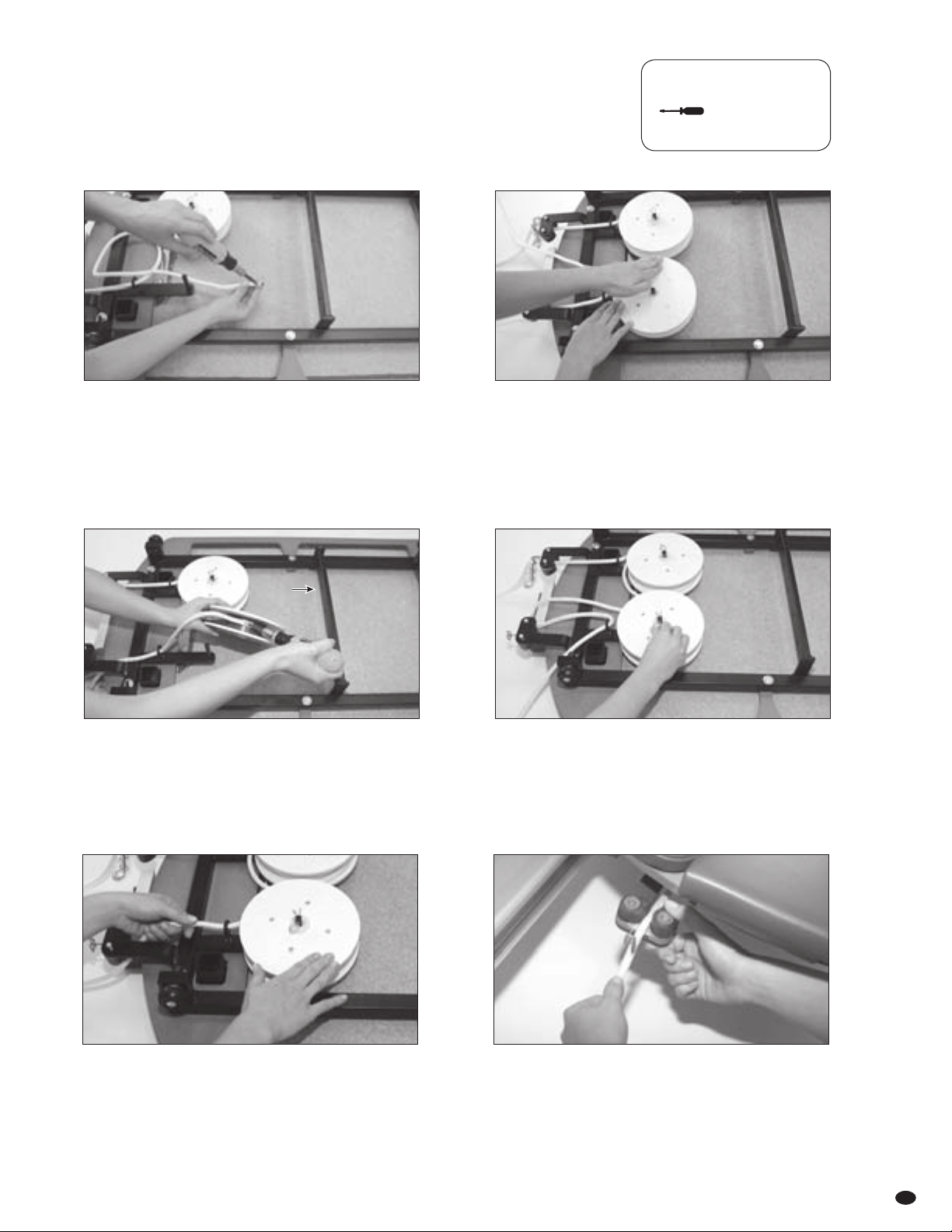
Replacing Retractable Ropes CONT’D
7 Place screw and rimmed washer directly in the center of
replacement rope, 1⁄2” from the end and thread completely
through rope.
NOTE: Screw must be placed exactly in the center
of rope to create a secure and safe interlock with rope
housing reel.
9
11 Wind rope around rope housing reel so rope lays flat
against hub. There should be some resistance on reel
and you should hear clicking as spring mechanism
engages. Recoil full length of rope.
8 To determine the direction rope must coil, place
empty reel on square shaft. Rotate reel in each direction.
An audible clicking sound will indicate the correct
direction to wind reel.
10 Place reel back on square shaft and replace
plastic washer. Secure cotter pin so middle curve
fits over square shaft.
12 Replace carriage (see page 24 for full instructions)
or return reformer to upright position.
Feed ropes through pulleys, attach Reformer loops
and set ropes to desired length (see pages 10 - 12).
Reset ropes between self-locking cleats then set fully
into rope retaining hooks.
REQUIRED TOOLS:
one flat-head screwdriver
Reel Direction
Reformer Owner’s Manual
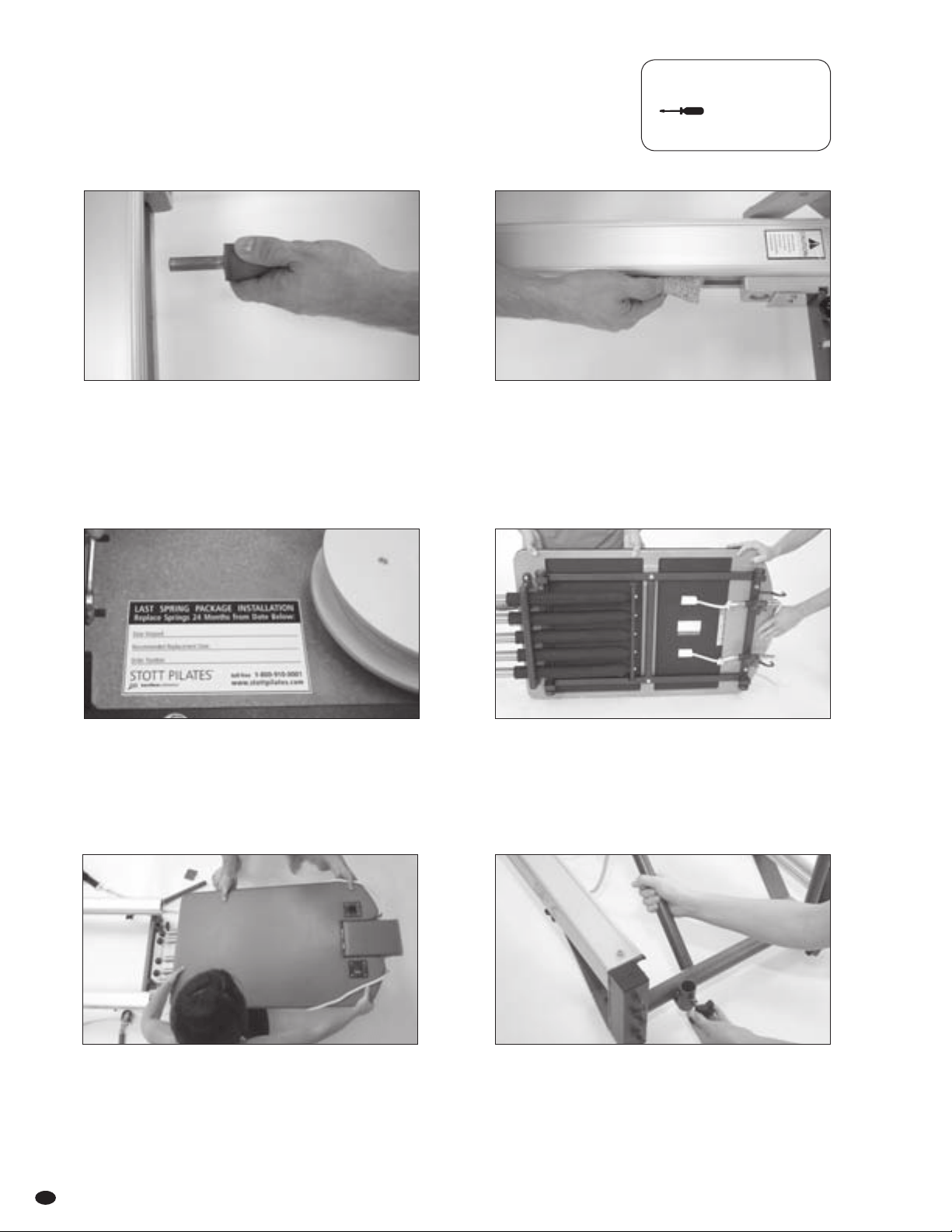
24
Replacing Carriage
1 Remove carriage stopper.
3 Write date of installation on the sticker provided with
spring replacement package. Affix sticker on the underside
of Reformer carriage.
Springs should be replaced every 24 months, or as needed
within that period.
5 Align fixed rollers with c-channels, then adjust floating
rollers as necessary before guiding carriage into rails.
CAUTION: Westrongly advise that two people perform
this operation to prevent damaging rollers.
2 Wipe inside of aluminum rails (c-channels) with a damp
cloth to remove dust or dirt. Spray onto cloth first.
Avoid spraying liquid directly onto surfaces,
rollers or rails.
Insert carriage stopper in one of six positions.
4 Ensure pulleybars are still on either side of aluminum rails.
Carefully turn carriage over. Ensure rollers are secure
and do not come in contact with the floor
NOTE: Requires two people.
REQUIRED TOOLS:
one flat-head screwdriver
6 ALL MODELS: Insert pulleybars into receptacles at back of
Reformer and tighten star knobs. Ensure eyehooks on top
of pulleybars are parallel to rails.
PROFESSIONAL & REHAB MODELS: Align top of pulleys
with top of shoulder rests.
merrithew.com 25
Replacing Carriage CONT’D
8 Replace shoulder rests and attach springs to gearbar.
NOTE: Ensure carriage stopper is in place before
attaching springs.
7
VERTICAL FRAME MODELS: Slide vertical frame into
receptacles. For plus-style models, position pulley system
facing carriage. For traditional models, position highest
eyehooks facing carriage. Tighten all four hex bolts.
Attach springs, roll-down bar and safety chain as illustrated
on page 5 [fig I].
REQUIRED TOOLS:
one flat-head screwdriver
1/2"(13mm) x 9/16"(14mm) or pliers
Reformer Owner’s Manual
Replacement Parts
FOOTBAR
With 1⁄4” hex key, fasten footbar to the
large swing arm bars with socket head cap
screws. With footbar in place, apply pressure
to footbar before tightening socket head
cap screws. Tighten completely only when
both sides of footbar are attached to ensure
proper alignment.
NOTE: Socket head cap screws are attached
to the ends of the replacement footbar when
it is shipped.
PULLEY BLOCK FIXED & TRAVELING
w Unscrew threaded bolt [57] that passes
through end shaft of pulley block and
the left and right arms of the swivel
harness [58].
w Remove swivel harness from eyehook
[54], and remove pulley block and
replace with new pulley block.
w Pass swivel harness through eyehook.
w Pass bolt through right side of swivel
harness and the center of the end shaft
of pulley block.
w Screw bolt through left side of
swivel harness.
FIXED ROLLERS
Attach fixed rollers with the aid of a
ratchet and 1⁄2” socket attachment.
CAUTION: Never use oil lubricants
as they may damage rollers.
FLOATING ROLLERS
With carriage removed from aluminum
rails, (see page 18) slide floating rollers into
bronze bushings. Replace carriage
(see page 24).
CAUTION: Never use oil lubricants as they
may damage rollers.
SPRING CLIPS
Replace spring clips every 12 months or
earlier as needed.
CAUTION: Locking spring clips must be
used to attach push-thru springs to the
vertical frame from below. Do not use
non-locking spring clips.
PADDED SHOULDER RESTS
NOTE: Only shoulder rest pads are shipped
for replacement. Loosen bolts on handle
frames, remove worn pads, replace with
new and tighten bolts.
CARRIAGE STOPPER
NOTE: Only one is needed per Reformer.
Must be in one of the six positions
AT ALL TIMES.
SAFETY CHAIN
For use with push-thru bar.
57
58
Floating Roller
Bronze Bushing
REFORMER ROPES
RETRACTABLE ROPE SYSTEM: See page 22
for installation.
54
26
merrithew.com
Replacement Parts CONT’D
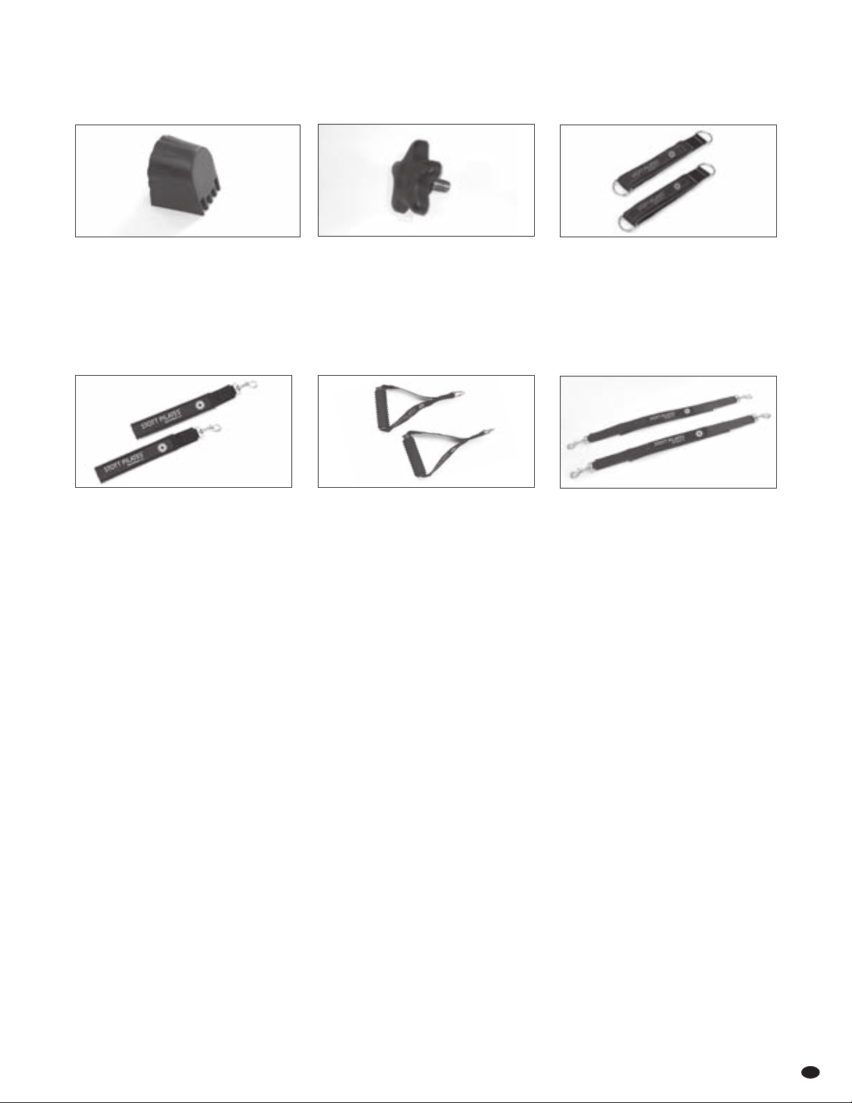
FOAM GRIP HANDLES
Provide cushioned hand grips for reformer
arm work, or attach to light arm springs
for use with vertical frame.
EXTENSION STRAPS
Used between leg springs and soft
reformer loops or padded long spine straps
to provide extra length.
PADDED LONG SPINE STRAPS
Attach to soft reformer loops to extend the
length. Also attach to leg springs
for leg work with any vertical frame.
STAR KNOB
Found in several locations on all
Reformer models.
SOFT REFORMER LOOPS
Attach to reformer ropes for arm
and leg work.
PLASTIC FOOT
For use on Professional and Rehab
Reformers.
Reformer Owner’s Manual
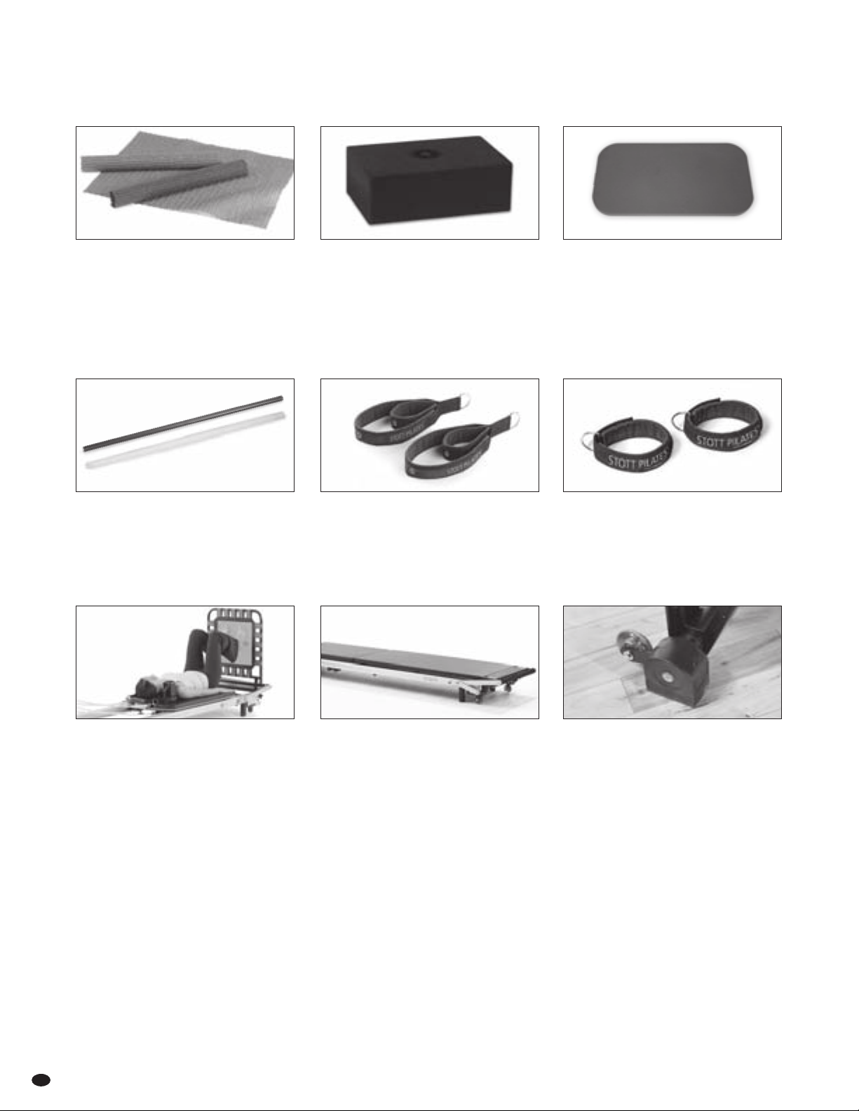
Optional Items
FOAM CUSHIONS
Available in three sizes. Used for comfort
and additional support when performing
a wide variety ofexercises.
GRIPPER MATS
Non-slip rubber mats are handy to
increase traction and prevent slipping.
A gripper mat can be wrapped around
push-thru bar, roll-down bar, uprights
or placed on upholstered bed.
TPE PILATES PADS
Non-slip eco-friendly pads can help
establish correctalignment and positioning
or to provide cushionedsupport.
MAT CONVERTER
The addition of a mat converter creates
a safe, stable surface for matwork or
vertical frame work.
Installing the Mat Converter
w Remove footstrap (if applicable), lower
footbar completely and detach springs.
w Slide carriage back against pulleybars,
ensuring ropes are out of the way.
w Place mat converter on aluminum rails,
ensuring it is pressed completely into place.
w Remove shoulder rests to create a clear
mat surface.
ACCESSORY BOARDS
Accessory boards can be added to further
increase exercise options. Currently available:
w Jumpboard and Cardio-Tramp™ for
plyometric exercises.
w Rotational Diskboard™ for controlled
internal and external rotation.
w Rotational Diskboard Deluxe™ allows
greater range and asymmetrical movements
when working in controlled rotation.
w Soft footbar accommodates sensitive feet.
Installing accessory boards
w Lower footbar to lowest position.
w Insert accessory board into receptacles in
wooden standing platform, ensuring it
slides down fully.
w Tighten star knobs on receptacles,
located under wooden standing platform.
HIGH TRACTION
REFORMER FEET
High traction reformer feet provide superior
grip on all types of floor surfaces during
high energy exercises when using the
Cardio-Tramp™ Rebounder or the Jumpboard.
Available with or without wheels. Sold in sets
of two. To upgrade an existing reformer, four
feet are required.
MAPLE & METAL
ROLL-UP POLE
Provides added scapular awareness.
(sold separately)
DOUBLE LOOP STRAPS
Conveniently switch from arm work to
leg work without having to detach straps.
ANKLE STRAPS
Attach to reformer ropes and fasten around
ankles to provide a more secure connection
for leg work.
find new image
find new image
28

merrithew.com
FOOTSTRAP
INCLUDED WITH REFORMER BOX PURCHASE
The footstrap is used to secure the feet
during most “short box” exercises.
Attaching the footstrap
w Loop footstrap around wooden standing
platform and adjust the length by attaching
spring clip to one of three D-rings.
w Footstrap should be adjusted so that there
is tension with knees slightly flexed. It is
important to keep feet hooked securely
under footstrap.
w Gripper mat may be used.
Optional Items CONT’D
REFORMER BOX
Reformer boxes are used to facilitate
or vary exercises. There are a range
of exercises in the Reformer repertoire
that require the use of a box.
Positioning the Reformer Box
w Place reformer box on top of carriage
with either long or short side pressed
against shoulder rests.
w In the “short box” position, box can
also be placed over shoulder rests with
the headrest fully lowered.
PADDED PLATFORM
EXTENDER
This accessory extends the wooden
standing platform and can accommodate
a variety of exercises, providing added
comfort and safety. It can also be used
on the carriage for seated exercises.
Installing the padded
platform extender
w Remove footstrap (if applicable)
and lower footbar completely.
w Place desired springs in gearbar.
w Place padded platform extender on
aluminum rails. Press it firmly against
wooden standing platform to ensure
it does not move.
w Gripper mats may be placed on carriage
and padded platform extender to prevent
slipping. (See page 13 for Safety &
Usage: Getting on the Reformer)
w Always remove padded platform
extender to change spring settings.

Reformer Owner’s Manual
30
CAUTION
STOP! Before getting on, ensurethat the carriage stopper
is inserted and at least one spring is securely attached
to the gearbar!
IMPROPER USE OF EXERCISE EQUIPMENT MAYCAUSE SERIOUS
BODILY INJURY. TO REDUCE RISK, PLEASE READ THE FOLLOWING:
w Before starting any exercise program, consult a physician.
w Before using the equipment, read and follow Safety
instructions in this Manual and obtain thorough instruction
from a qualified trainer.
w NEVER stand with both feet on wooden standing platform of
an SPX Max™ Reformer. Step onto secured carriage first before
placing one foot onto wooden standing platform. Always keep
one foot on secured carriage.
w Before moving a STOTT PILATES® Reformer, ensure ropes
do not drag and springs are attached so carriage is secure.
w Ensure the equipment is properly adjusted for yoursize
and ability level.
w Stop exercising immediately if you experience chest pain, feel
faint, have difficulty breathing or experience any discomfort.
w Keep body, clothing and hair free from all movingparts.
w Do not use if equipment appears worn, brokenordamaged.
w Do not attempt to repair equipment yourself.
w Do not allow children to use or be around equipment without
adult supervision.
w For optimal performance, allow at least two feetofclear space
on either side of a STOTTPILATESReformer.
w When springs are used on the vertical frame, ensure spring clips
are fully closed at both ends of springs. A spring clip that is only
half closed risks coming undone and detaching with high force.
w When using the push-thru bar with springs attached from
below, a trained professional must keep a hand on the
bar at all times, and the safety chain must be attached.
(See Safety & Usage on page 16.)
Warranty
MERRITHEW HEALTH & FITNESS REFORMERS
Merrithew Health & Fitness™ warrants that all new equipment is are free of
manufacturing defects in workmanship and materials, subject to the terms
below. This warranty becomes effective at the invoice date of the original
purchase. Parts repaired or replaced under the terms of this warranty will
be warranted for the remainder of the original warranty period.
This warranty applies to equipment only:
w while it remains in the possession of the original purchaser and
proof of purchase is demonstrated
w if claims are made within the warranty period
w if upgrades are made as required by Merrithew Health & Fitness
THIS WARRANTY SHALL BE NULL AND VOID SHOULD:
w the equipment is used for any other purpose other than as intended
w all safety and usage guidelines arenot followed as specified
w if equipment failure is a result of improper maintenance
w
if equipment has been subjected to accident, misuse, abuse, improper
service, or any modification not authorized by Merrithew Health & Fitness
This warranty does not cover damage to the finish of any
Merrithew Health & Fitness equipment, or shipping charges, customs
clearance fees (if applicable) or any costs incurred in installing repaired
or replacement parts shipped under the provisions of this warranty.
LIMITED LIFETIME WARRANTY
Merrithew Health & Fitness will, at its option, repair or replace any
of the parts listed below, provided that the part(s) fail due to a defect
in workmanship or materials:
w Aluminum Rails
w Components of the frame and related welding
w Gearbar
w Footbar mechanism
ONE (1) YEAR LIMITED WARRANTY
On ropes, straps, spring clips, plastic pulley bar receptacle sleeves,
non-skid tape on footbar, comfort footbar, carriage stopper and plastic
reformer feet. We recommend that spring clips (including those
attached to traditional-style ropes) be changed annually.
TWO (2) YEAR LIMITED WARRANTY
Merrithew Health & Fitness will, at its option, repair or replace all other
components, including molded spring holder, that fail for any reason,
provided such failure is reported to Merrithew Health & Fitness within
a period of two years from the invoice date of the original purchase.
90-DAY FABRIC WARRANTY
The vinyl fabric upholstery and spring sleeves will be replaced if it fails to give
normal wear for 90 days after delivery. Proof of damage may be required. This
warranty does not cover cuts, burns, stains, soiling, pet damage or damage
caused by other unreasonable use. This warranty does not apply to fabrics
cleaned with abrasive, corrosive or chemical cleansers. If the identical fabric
is not available, Merrithew Health & Fitness will provide an equivalent fabric.
DISCLAIMER OF IMPLIED WARRANTIES AND
LIMITATION OF REMEDIES
Repair or replacement of defective parts is your exclusive remedy under
the terms of this limited warranty. In the event of parts availability issues,
Merrithew Health & Fitness will not be responsible for any consequential
or incidental damages arising from the breach of either this limited
warranty or any applicable implied warranty, or for failure or damage
resulting from acts of nature, improper care and maintenance, accident,
alteration, replacement of parts by anyone other than Merrithew Health
& Fitness, misuse, transportation, abuse, hostile environments (inclement
weather, acts of nature), improper installation or installation not in
accordance with local codes or printed instructions.
This limited warranty is the sole express warranty given by Merrithew
Health & Fitness. No product performance, specification or description
wherever appearing is warranted by Merrithew Health & Fitness except to
the extent set forth in this limited warranty. Any implied warranty protection
arising under the laws of any state, provinceor territory including implied
warranty of merchantability or fitness for a particular purpose, oruse, is
hereby limited in duration to the duration of this limited warranty.
Neither dealers, web resellers, nor the retailers selling this product have
any authority to make any additional warranties or to promise remedies
in addition to or inconsistent with those stated above. Merrithew Health
& Fitness maximum liability, in any event, shall not exceed the purchase
price of the product paid by the original purchaser.
merrithew.com 31
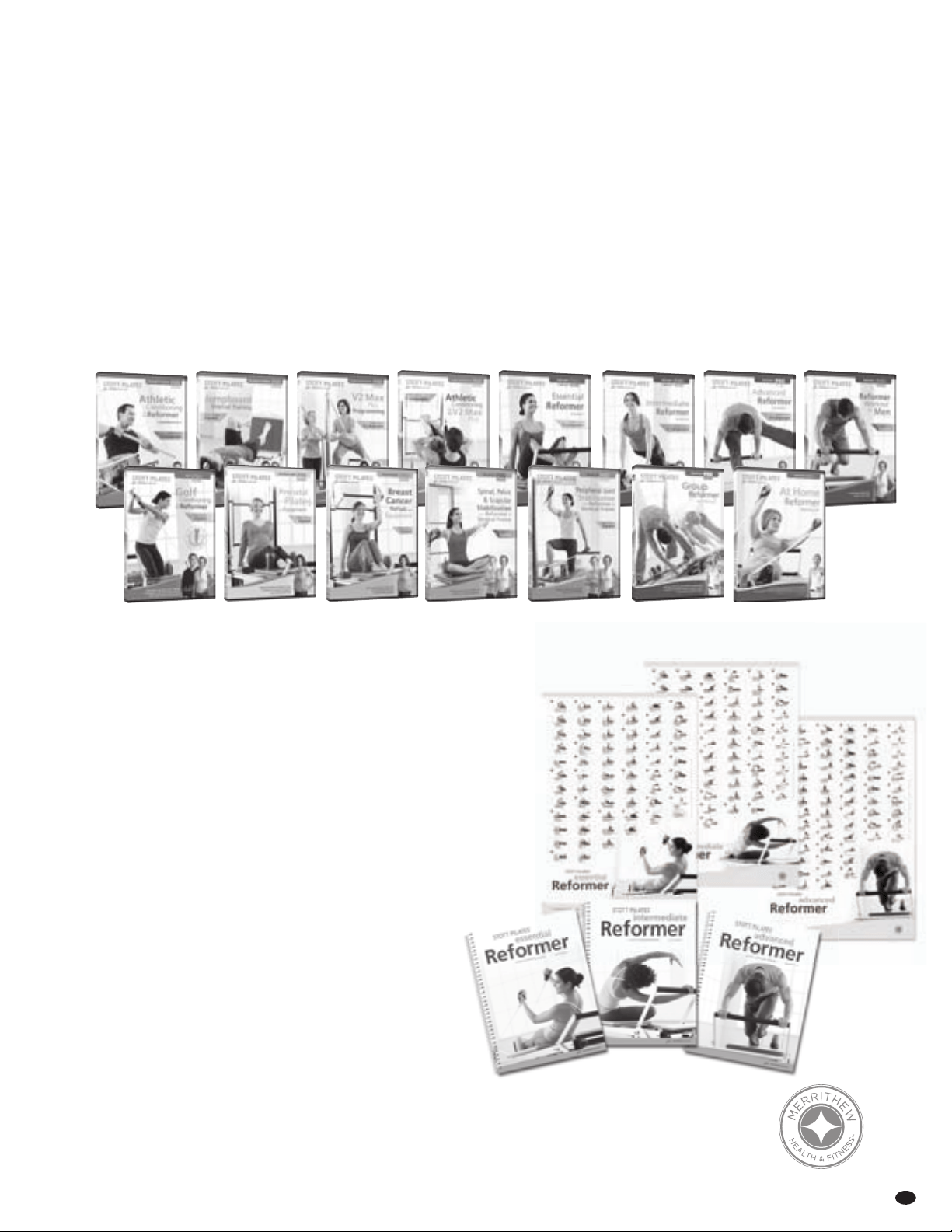
Choose from a variety of
cutting-edge DVD titles
Increase your expertise with Reformer instruction.
Expand Your Repertoire
Contact Us Today:
visit merrithew.com
or call toll-free North America 1-800-910-0001
United Kingdom 0800-328-5676
or International +1-416-482-4050
A step-by-step exercise guide for the reformer repertoire
can be downloaded by visiting merrithew.com/guide
Reformer
Guides & Charts
This full-size wall chart depicts exercises featured in
the STOTT PILATES® Reformer programs. Each exercise
is described with name, equipment accessories,
one photo, as well as suggested repetitions.
Wall Chart 27 x 39 in

2200 Yonge Street, Suite 500, Toronto, ON, M4S 2C6 416-482-4050
416-482-2742 [email protected] merrithew.com
Please keep this manual in a safe place.
IMPORTANT
This is your Reformer Serial Number:
P00179-01 2082B-2 JULY 12 ™/® Trademark or registered trademark of Merrithew Corporation, used under license. Printed in Canada. All rights reserved. *US Patent No. 7857736, 5792033, 2179793 and other US and foreign patents pending.