
Loading ...
Loading ...
Loading ...
32
8) In bad or severe water conditions, clean the oat switch as described below. Otherwise,
continue to step 9.
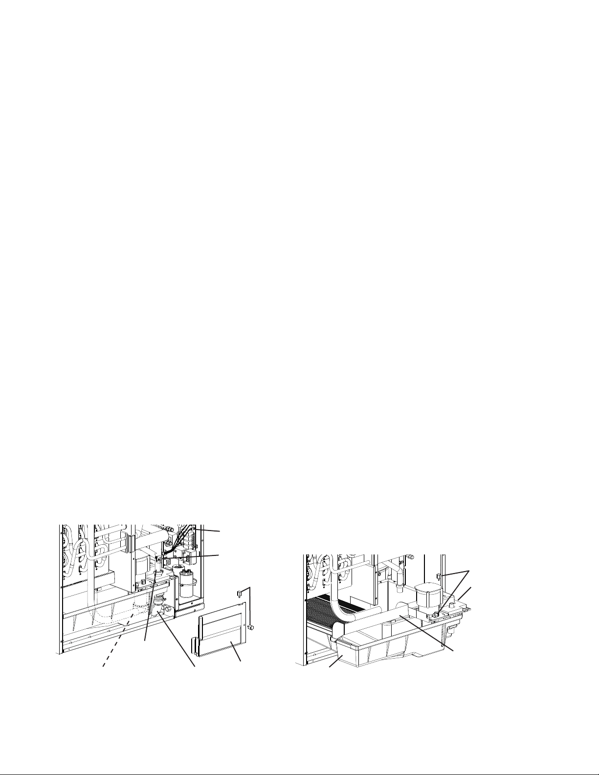
a. Remove the control box cover. Remove the 2 thumbscrews securing insulation
panel (B), then remove insulation panel (B). See Fig. 19.
b. Disconnect the discharge hose, the drain valve drain hose, and the overow drain
hose.
c. Disconnect the pump motor connector from the back of the control box, then
disconnect the oat switch connector from the control board.
d. Remove the 2 thumbscrews securing the pump motor and oat switch assembly.
See Fig. 20.
e. Pull out the water tank, cube guide, and pump motor and oat switch assembly
together.
f. Remove the screw securing the oat switch to the top of the assembly. Remove the
oat switch from the assembly.
g. Remove the retainer rod from the bottom of the oat switch, then remove the oat.
Be careful not to bend the retainer rod excessively when removing it.
h. Wipe down the oat switch housing, shaft, oat, and retainer rod with cleaning
solution. Rinse the parts thoroughly with clean water.
i. Reassemble the oat switch. Replace the oat switch in its correct position, then
secure with the screw.
j. Replace the removed parts in the reverse order of which they were removed.
9) Pour the cleaning solution into the water tank.
10) Move the service switch to the "WASH" position.
11) Replace insulation panel (A) and the front panel in their correct positions.
12) Turn on the power supply to start the washing process.
13) Turn off the power supply after 30 minutes.
14) Remove the front panel.
15) Move the service switch to the "DRAIN" position.
16) Replace the front panel in its correct position, then turn on the power supply for
2 minutes.
Fig. 20
Fig. 19
Thumbscrews
Insulation
Panel (B)
Pump Motor
Connector
Float Switch
Connector (Black)
Drain Valve
Drain Hose
Overow
Drain Hose
Discharge Hose
Thumbscrews
Water Tank
Cube Guide
Pump Motor
and Float
Switch
Assembly
Loading ...
Loading ...
Loading ...