Loading ...
Loading ...
Loading ...
Checking Manifold Gas Pressure
Disconnect the range and its individual shut-off valve from the gas
supply piping system during any pressure testing of that system at
test pressures greater than 14" of water column pressure
(approximately 1/2" psig).
The appliance must be isolated from the gas supply piping system
by closing its individual manual shut-off valve during any pressure
testing of the gas supply piping system at test pressures equal to
or less than 14" of water column pressure (approximately 1/2"
psig).
If it should be necessary to check the manifold gas pressure,
connect manometer (water gauge) or other pressure device to the
top burner right rear orifice. Using a rubber hose with inside
diameter of approximately 1/4," hold tubing down tight over orifice.
Turn burner valve on.
For an accurate pressure check have at least two (2) other top
burners burning. Be sure the gas supply (inlet) pressure is at least
one inch above specified range manifold pressure. The gas
supply pressure should never be over 14" water column. When
properly adjusted for Natural Gas the manifold pressure is 4." (For
LP/Propane Gas the manifold pressure is 10.")
5. Read electrical connection details below and connect
electricity to range.
_!V,V-,I_I_II_[Lll Before servicing, disconnect electrical
supply at circuit breaker, fuse or power cord.
Electric Requirements: An individual, properly grounded and
polarized branch circuit protected by a 15 amp. circuit breaker or
time delay fuse. See serial plate for proper voltage.
Extension Cord Precautions:
Because of potential safety hazards under certain conditions, we
strongly recommend against the use of any extension cord.
However, if you still elect to use an extension cord, it is absolutely
necessary that it be a UL listed 3-wire grounding type appliance
extension cord and that the current carrying rating of the cord in
amperes be equivalent to or greater than the branch circuit rating.
Such extension cords are obtainable through your local service
organization.
PLEASE READ CAREFULLY! For personal
safety, this product must be properly grounded.
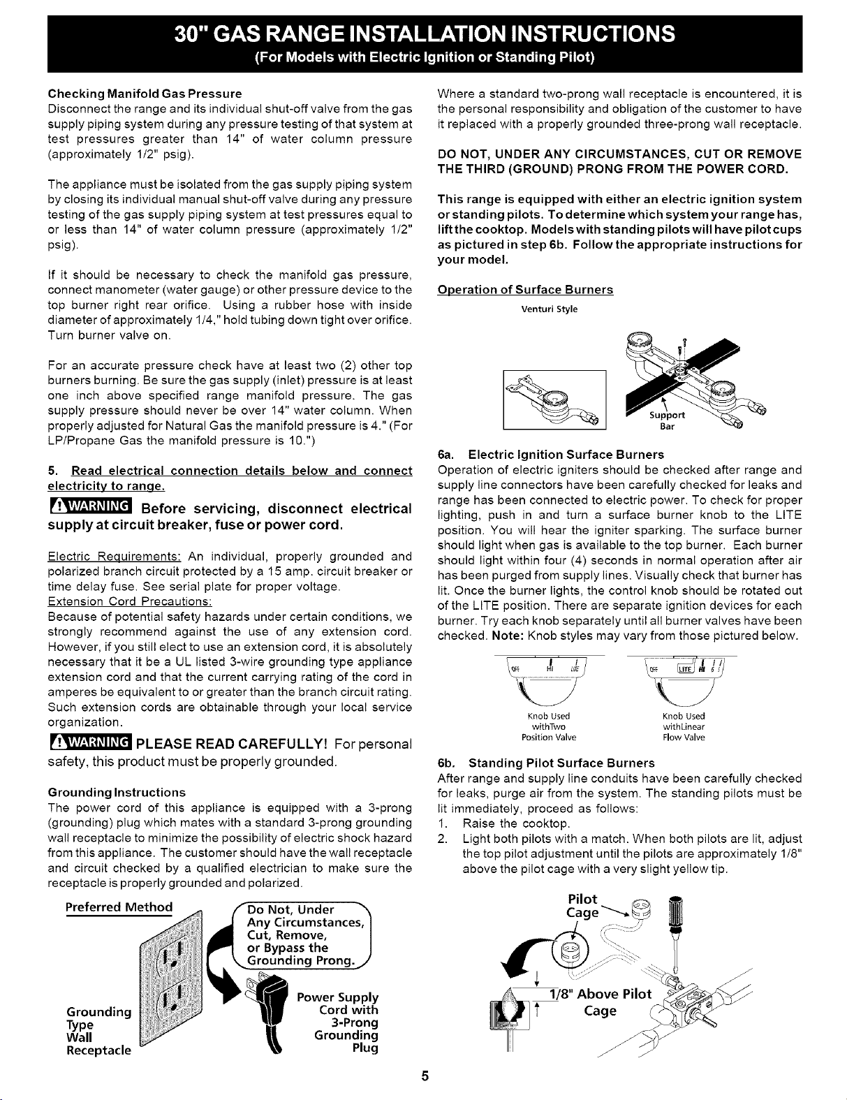
Grounding Instructions
The power cord of this appliance is equipped with a 3-prong
(grounding) plug which mates with a standard 3-prong grounding
wall receptacle to minimize the possibility of electric shock hazard
from this appliance. The customer should have the wall receptacle
and circuit checked by a qualified electrician to make sure the
receptacle is properly grounded and polarized.
Preferred Method /fDo Not, Under _,
_Any Circumstances, I
_Cut, Remove, |
_1 or Bypass the J
Grounding Prong. j'
__ Power Supply
Grounding Cord with
Type 3-Prong
Wall Grounding
Receptacle Plug
Where a standard two-prong wall receptacle is encountered, it is
the personal responsibility and obligation of the customer to have
it replaced with a properly grounded three-prong wall receptacle.
DO NOT, UNDER ANY CIRCUMSTANCES, CUT OR REMOVE
THE THIRD (GROUND) PRONG FROM THE POWER CORD.
This range is equipped with either an electric ignition system
or standing pilots. To determine which system your range has,
lift the cooktop. Models with standing pilots will have pilot cups
as pictured in step 6b. Follow the appropriate instructions for
your model.
Operation of Surface Burners
Venturi Style
;upport
Bar
6a. Electric Ignition Surface Burners
Operation of electric igniters should be checked after range and
supply line connectors have been carefully checked for leaks and
range has been connected to electric power. To check for proper
lighting, push in and turn a surface burner knob to the LITE
position. You will hear the igniter sparking. The surface burner
should light when gas is available to the top burner. Each burner
should light within four (4) seconds in normal operation after air
has been purged from supply lines. Visually check that burner has
lit. Once the burner lights, the control knob should be rotated out
of the LITE position. There are separate ignition devices for each
burner. Try each knob separately until all burner valves have been
checked. Note: Knob styles may vary from those pictured below.
Knob Used Knob Used
withTwo withLinear
Position Valve Flow Valve
6b. Standing Pilot Surface Burners
After range and supply line conduits have been carefully checked
for leaks, purge air from the system. The standing pilots must be
lit immediately, proceed as follows:
1. Raise the cooktop.
2. Light both pilots with a match. When both pilots are lit, adjust
the top pilot adjustment until the pilots are approximately 1/8"
above the pilot cage with a very slight yellow tip.
1/8" Above Pilot
i' Cage
Loading ...
Loading ...
Loading ...