Loading ...
Loading ...
Before Starting
Tools You Will Need
For leveling legs and Anti-Tip Bracket:
Adjustable wrench or channel lock pliers
5/16" Nutdriver or Fiat Head Screw Driver
Electric Drill & 1/8" Diameter Drill Bit (5t32" Masonry Drill Bit
if installing in concrete)
For gas supply connection:
Pipe wrench
For burner flame adjustment:
Phillips head _ and
blade-type screwdrivers
For gas conversion (LP/Propane or Natural):
Open end wrench - 1/2"
Additional MaterialsYou Will Need
Gas line shut-off valve
Pipe joint sealant that resists action of LP/Propane gas
A new flexible metal appliance conduit (1/2" NPT x 3/4" or 1/
2" I.D.) must be design certified by CSA International. Because
solid pipe restricts moving the range we recommend using a
new flexible conduit (4 to 5 foot length) for each new installation
and additional reinstallations.
Always use the (2) new flare union adapters (1/2" NPT x 3/4"
or 1/2" I.D.) supplied with the new flexible appliance conduit
for connection of the range.
Normal Installation Steps
1. Anti-Tip Bracket Installation Instructions
Important Safety Warning
To reduce the risk of tipping of the range, the range must be
secured to the floor by properly installed anti-tip bracket and
screws packed with the range. Failure to install the anti-tip bracket
will allow the range to tip over if excessive weight is placed on an
open door or if a child climbs upon it. Serious injury might result
from spilled hot liquids or from the range itself.
If range is ever moved to a different location, the anti-tip brackets
must also be moved and installed with the range.
Instructions are provided for installation in wood or cement fastened
to either the floor or wall. When installed to the wall, make su re that
screws completely penetrate dry wall and are secured in wood or
metal. When fastening to the floor or wall, be sure that screws do
not penetrate electrical wiring or plumbing.
A,
B,
Locate the Bracket Using the
Template - (Bracket may be
located on either the left or
right side of the range. Use
the information belowto locate
the bracket if template is not
available). Mark the floor or
wall where left or right side of
the range will be located.
if rear of range is against the
wall or no further than 1-1/4" from wall when installed, you may
use the wall or floor mount method. If molding is installed and
does not allow the bracket to fit flush against the wall, remove
molding or mount bracket to the floor. For wall mount, locate the
bracket by placing the back edge of the template against the rear
wall and the side edge of template on the mark made referencing
the side of the range. Place bracket on top of template and mark
location ofthe screw holes in wall. If rear of range is further than
1-1/4" from the wall when installed, attach bracket to the floor.
For floor mount, locate the bracket by placing back edge of the
template where the rear of the range will be located. Mark the
location of the screw holes, shown in template.
Drill Pilot Holes and Fasten Bracket - Drill a 1/8" pilot hole
where screws are to be located. If bracket is to be mounted to
the wall, drill pilot hole at an approximate 20 ° downward angle.
If bracket is to be mounted to masonry or ceramic floors, drill a
5/32" pilot hole 1-314" deep. The screws provided may be used
in wood or concrete material. Use a 5/16" nut-driver or flat head
screwdriver to secure the bracket in place.
FASTEN BRACKET (w¢¢_ o_ FLO0_MOUNllNG) FASTEN BRACKET (FLOORMOUN_NG ONLY)
Leveling Leg -- --iPI 14--1-1/4 " Max. -More Than
Leveling Leg 1-1/4"
_Bracket
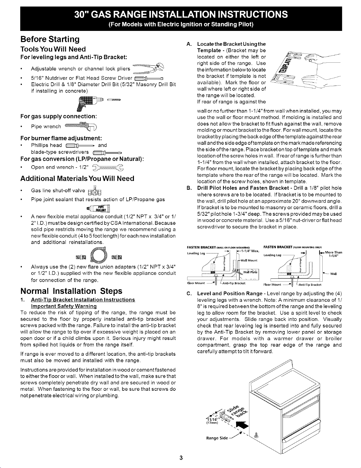
C,
Level and Position Range - Level range by adjusting the (4)
leveling legs with a wrench. Note: A minimum clearance of 1/
8" is required between the bottom of the range and the leveling
leg to allow room for the bracket. Use a spirit level to check
your adjustments. Slide range back into position. Visually
check that rear leveling leg is inserted into and fully secured
by the Anti-Tip Bracket by removing lower panel or storage
drawer. For models with a warmer drawer or broiler
compartment, grasp the top rear edge of the range and
carefully attempt to tilt it forward.
Loading ...
Loading ...
Loading ...